BUFFER UNIT - Made for Prusa MMU3

Description
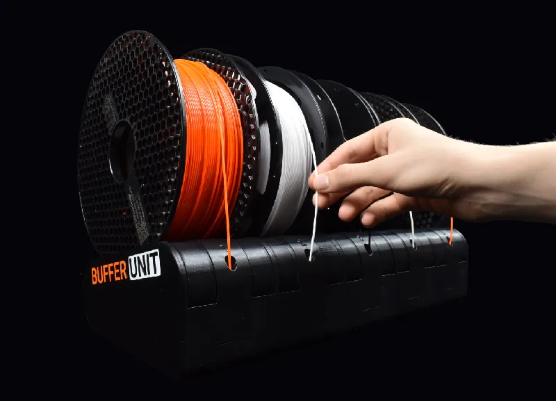
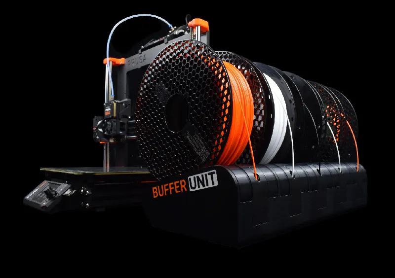
| The BUFFER UNIT is a premium rewindable spool holder for the MMU3/MMU2. It's compact and easy to use, opposed to the official clunky setup for the MMU. Compatible with the Prusa MK4, MK3, CORE One, Original Prusa Enclosure and more. |
Standout Features
- Rewindable 5 filament spool holder
- Super-easy to load filament
- Simple gravity powered rewind-mechanism
- Compact setup w/ PTFE guides
- Detailed assembly instructions - see bottom of page!
No Tedious Loading
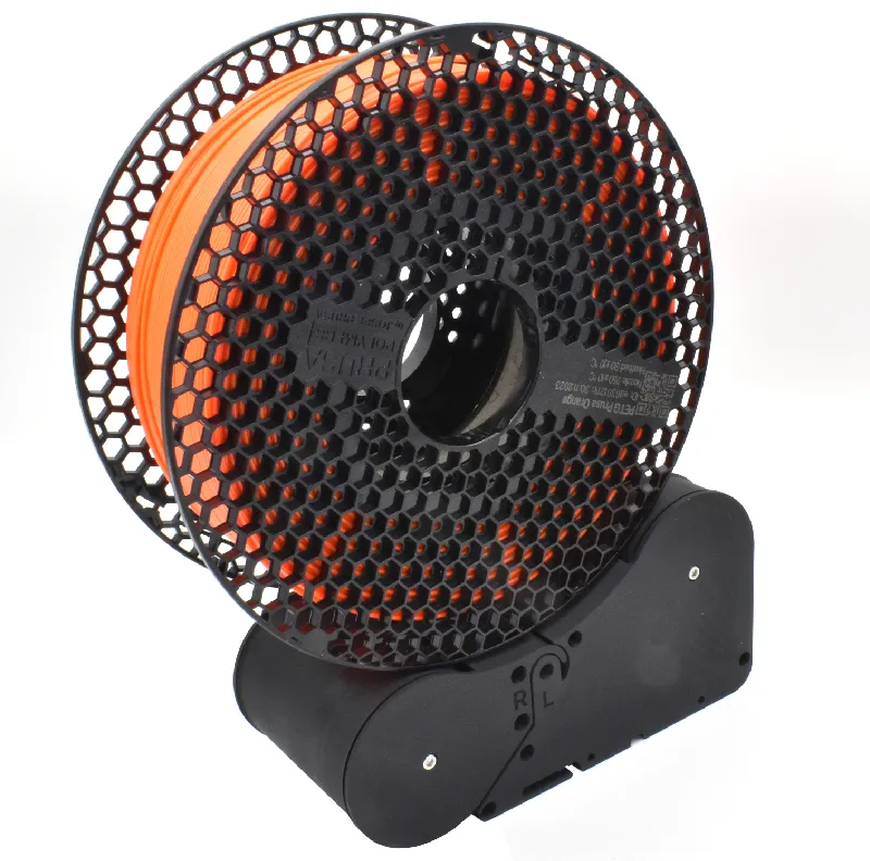
Loading filament is easy. Just place your spool on the rollers corresponding to the right filament number, then push the filament through the PTFE-tube till it reaches the MMU. That's it! The BUFFER UNIT rewinds the filament automatically when it unloads.
Lots Of Mounting Options
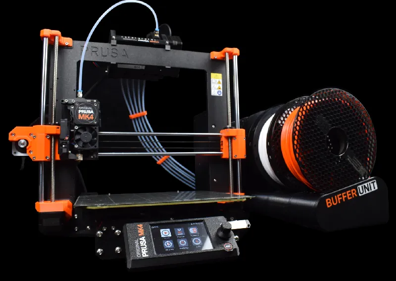
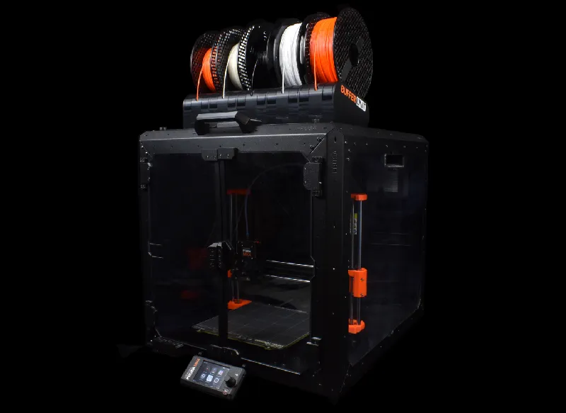
The BUFFER UNIT is compatible with the Prusa MK4/S, MK3/S/+, CORE One and Original Prusa Enclosure. Some parts are specific for your printer setup, you can find these for your setup:
- MK4/MK3
- Original Prusa Enclosure
- COREBOXX by @Voxel3D
- CORE One (coming soon)
→ Or create your own custom setup here!
ⓘ The BUFFER UNIT can still be used with the CORE One. I'm waiting for Prusa to support the MMU for the CORE One.
Minimal Space
The setup is small. Because the spool holders are rewindable, there is no need for an external buffer that takes up unnecessary space. And thanks to smart PTFE routing, the Buffer Unit can be placed very close to the printer. This also makes the filament path up to half the length compared to the official MMU-setup.
  |
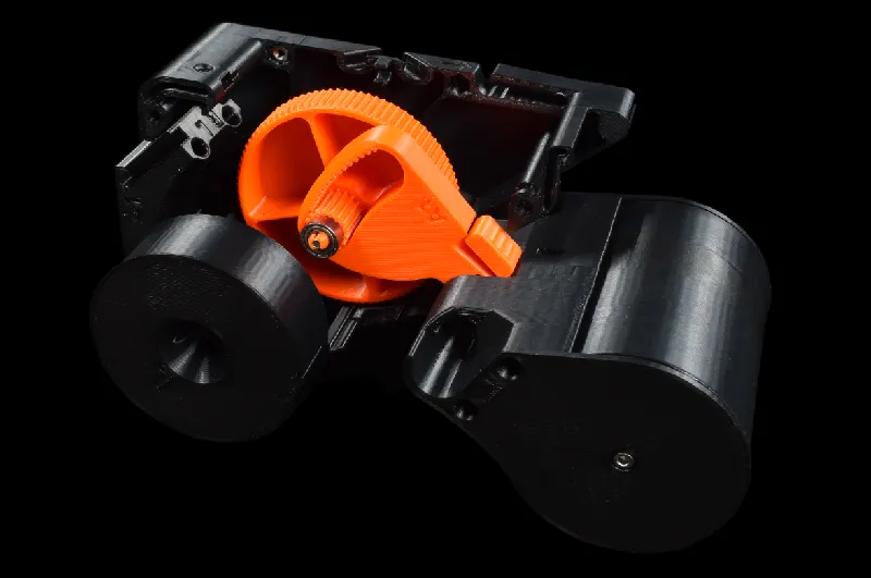
Powered By Gravity
No springs are needed for the rewind mechanism to work. The unit relies on storing potential energy by raising the spools themselves - and letting gravity wind back the spools when the MMU unloads. This is done via a gear train that moves the back-roller up or down, depending on which way the front-roller spins. When in the uppermost position, the spool simply slides on the front-roller until the MMU unloads.
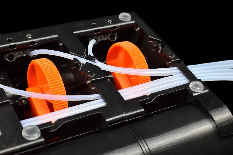
Efficient Tubing
The PTFE-tubes are routed inside the Buffer Unit via clips, and channels where the tubes can snap into place. It's designed with smooth filament paths, which form the PTFE-tubes into big arcs. Since the bends match the filament’s natural spool-curvate, the process of loading filament is much smoother.
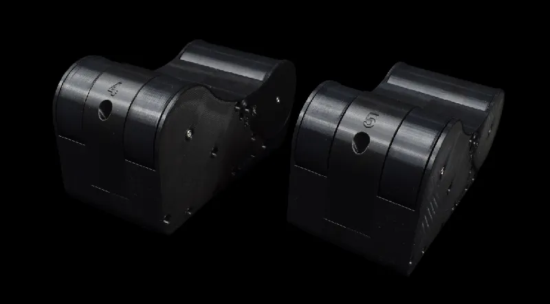
Modular Design
The BUFFER UNIT consists of 5 spool holder modules that can be chained together. The modularity helps to make the assembly easier to assemble, but also adds the possibility to customize the unit layout. I plan to publish modules that accept wider spools in the feature.
Product Development
I've never put as much effort into a single project as this one: the Buffer Unit is the culmination of 3 years and thousands of hours designing, testing and prototyping different MMU-solutions - and now it's finally here!
By-the-way, my name is Ludvig Broomé and I'm 19 years old student from Sweden and currently studying Mechanical Engineering. Three years ago I bought the MMU2 upgrade for my MK3. But, like many any others, I was unsatisfied with the large and non user-friendly setup required for the MMU. As a result, I wanted to design my own solution.
I've gone through tons of iterations. These are some examples. I've tried making buffers similar to the “RMU”, where unloaded filament is temporarily stored in a box. I made a switch for each filament, guiding the filament for you without you manually opening and loading the buffer. I've made tons of side-mounted rewindable spool holders. One where the whole mechanism was print-in-place, one was powered with springs, one had a cycloidal clutch-mechanism for when the spool-holder couldn't hold more energy and needed to skip. One design had an anti-overwinding mechanism where energy was released via a pendulum mechanism (the thing sounded like a loud clock). I've explored so many ideas that I could literally talk for days. But finally I set on a single spool unit design with rollers, something that eventually transformed into the Buffer Unit.
This is all to say that I've poured my heart and soul in to this product. I have really strived to make the BUFFER UNIT the ultimate MMU enhancer. I've tried to design it completely around the user-experience for the ground up - from how the parts are assembled to regular use. I really hope you like it <3
Technical Parameters
| Unit dimensions (XYZ) | 410mm x 180mm x 91mm |
| Total filament required (PLA) | <1300 grams |
| Approx. total print time (on MK4) | <70 hours |
| Assembly time | <1 hour |
| Spool width | 35 to 74mm |
| Spool material | Use printed spool adapters for cardboard spools |
| Approx. rewind length | 1.25 spool turns (200mm diameter) |
1. Parts List
| Item | Quantity |
| Recommended: 685 ZZ Bearing (5x11x5mm) ⓘ 686 ZZ Bearing (6x13x5) also supported | 40 |
| PTFE-Tube (OD 4mm, ID 2.5mm) | N/A |
| M3 Hex Nut | 40 |
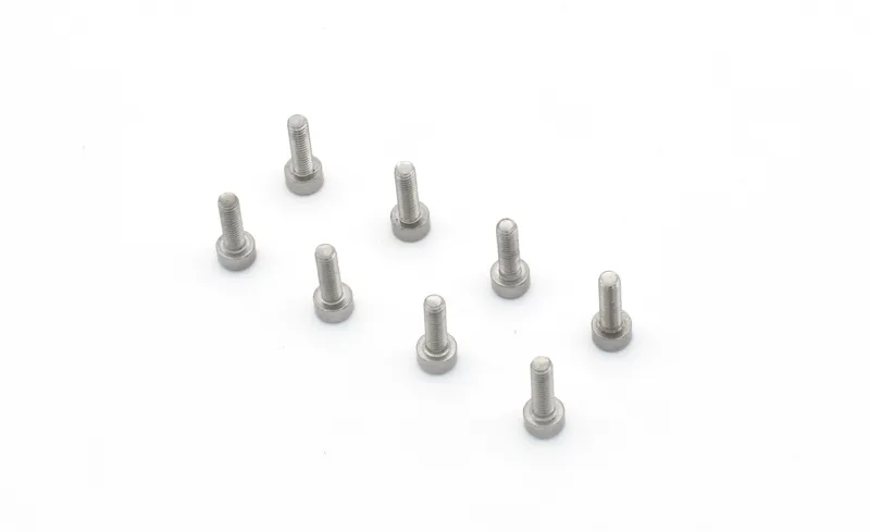
| M3x40 screw | 5 |
| M3x18 screw | 30 |
| M3x12 screw | 20 |
| M3x10 screw | 23 |
ⓘ If you don't have screws with the right length, slightly longer screws work as well! See extra parts for your specific printer setup:
| |
2. TPU-sleeves or not?
I recommend using standard PETG-rollers with no sleeves. Friction in the mechanism is what impacts reliability the most. That's why it's best to prioritize low-friction bearings and cleanly printed parts with low filament residue (e.g. remove stringing). Low resistance in the mechanism means that less roller-to-spool-grip is required to turn the mechanism. Test PETG-rollers first! If you find that the mechanism won't wound properly, check for friction. Then I suggest trying TPU-sleeves.
TPU grip varies from different brands. Here are examples from users:
✅TPU:s used with success from users:
- PrimaCreator™ EasyPrint FLEX TPU
- Filatech FilaFlexible40
- +More (let me know what works for you!)
❌ TPU:s with too much grip from users:
- Overture TPU
- Extrudr TPU Semisoft
- eSun TPU 95A
3. Previous version compatibility
If you haven't printed the previous versions, skip this part.
| Version A4 is compatible with the following parts from previous versions: | |
| A3 | ✅ Spur-gear, Ring-gear, R-Side-panel, L-Side-panel, 1- to 5-PTFE-Guides |
| A2 | ✅ Spur-gear, Ring-gear, R-Side-panel, L-Side-panel, 1- to 5-PTFE-Guides |
| A1 | ✅ 1- to 5-PTFE-Guides |
4. Printed parts
Print quality is key! Before assembly, check that all printed parts are printed correctly. Especially examine gears and rollers.
The print files tell you how many of each part you need to print. Decide between TPU-rollers and sleeve-less rollers.
5. Print Settings
0.2mm STRUCTURAL (PrusaSlicer)
NO SUPPORTS, 0.4mm NOZZLE, 0.2mm layer height, 15% infill, minimum 2 perimeters. PETG is recommended.
See part specific settings:
| L-Front-roller, R-Front-roller and Back-roller (NO SLEEVE) | Seams: “Scarf joint placement” to: “Everywhere” in PrusaSlicer. ⚠ IMPORTANT! Spools may get stuck on the seams if you don't use this setting. |
Assembly Manual
Pre-assembly Information
The manual is split into two parts:
The second part can be found for free on my Printables Page:
|
Tool preparation
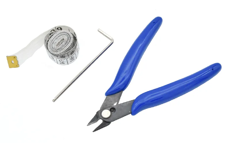 | Prepare the following tools: 2.5mm Allen key (for M3 screws) PTFE-cutter/Cutting pliers Measuring tape (for measuring PTFE-tubes) |
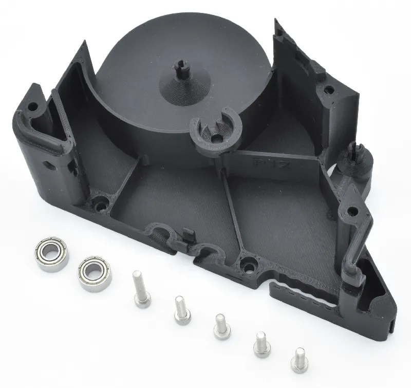
Step 1 R-Shell: Prepare parts
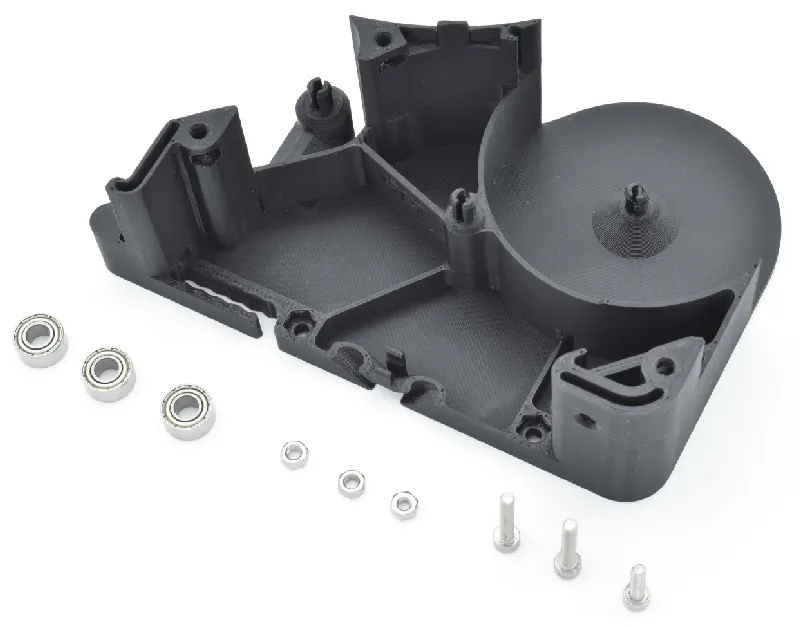 | Please prepare the following items: R-Shell (1x) Bearing (3x) M3 hex nut (5x) M3x18 screw (2x) M3x12 screw (1x) |
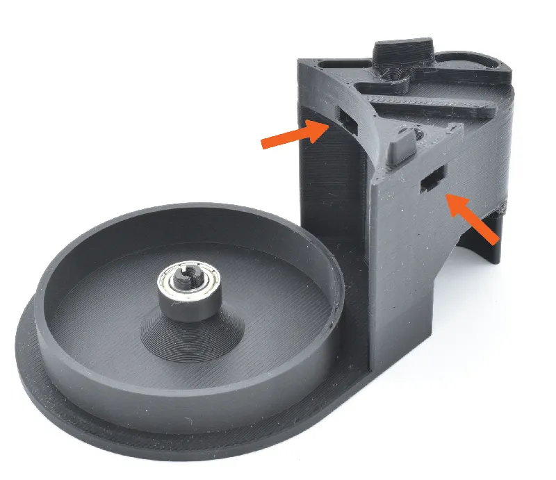
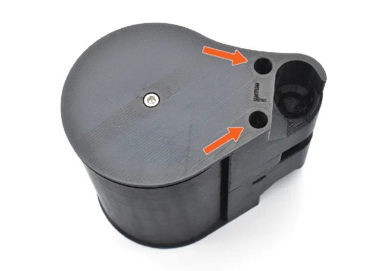
Step 2 R-Shell: Insert hex nuts
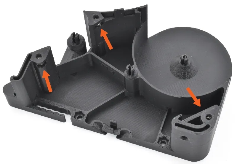 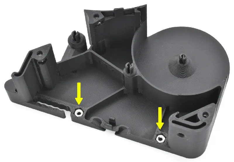 | 🟠Insert 3 hex nuts through the slots on the R-Shell. Press the nuts with a hex key to ensure proper insertion. 🟡Insert the remaining 2 M3 hex nuts according to the picture. |
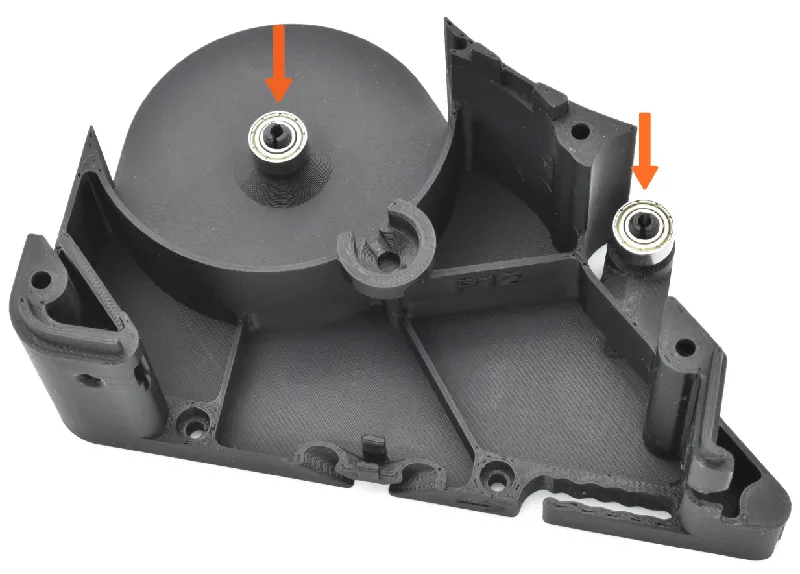
Step 3 R-Shell: Attach bearings
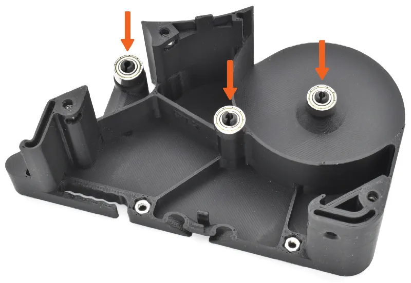  | 🟠Snap 3 bearings into place on top of the R-Shell's pins. 🟡Secure two of the bearings with two M3x18 screws according to the picture. 🟢 Secure the last bearing with a M3x12 screw. |
Step 4 Front-roller: Prepare parts
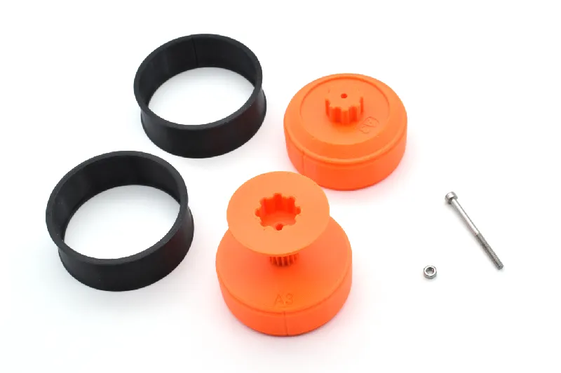 | Prepare the following items: R-Front-roller (1x) L-Front-roller (1x) Front-roller- M3 hex nut (1x) M3x40 screw (1x) ⚠ If you have rollers without TPU-sleeves, skip the parts attaching these. |
Step 5 Front-roller: Attaching TPU-sleeves
 | 🟠 Attach the Front-roller-sleeves onto the R- and L-Front-rollers. |
Step 6 Front-roller: Insert hex nut
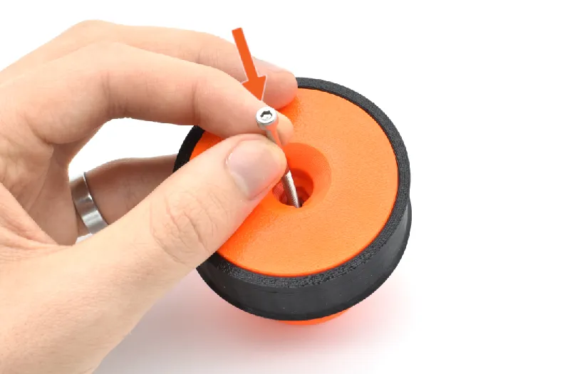 | 🟠Insert the M3 hex nut through the hole of the R-Front-roller. ⓘ To make insertion easier, take a long screw (e.g. M3x40) and thread the nut slightly. Then use the screw to insert the nut. |
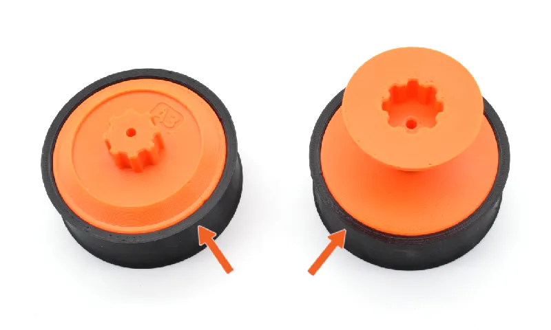
Step 7 Front-roller: Attach both sides
 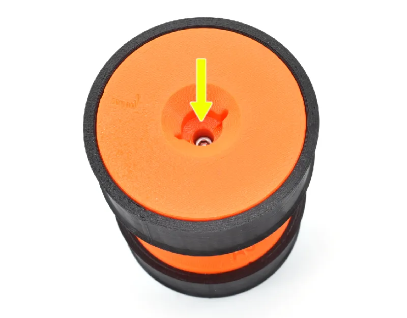 | 🟠Connect the R-Front-roller to the L-Front-roller. 🟡Insert the M3x40 screw through the R-Front-roller. Tighten it. |
Step 8 R-Shell: Attach Front-roller
 | 🟠Attach the Front-roller to one of R-Shell's bearings according to the picture. |
Step 9 Spur-gear: Prepare parts
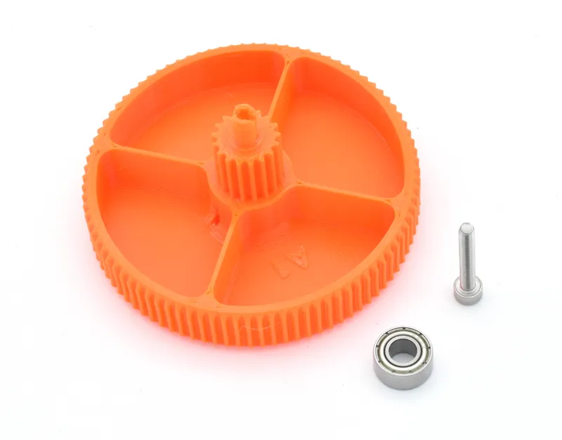 | Please prepare the following items: Spur-gear (1x) Bearing (1x) M3x18 screw (1x) |
Step 10 Spur-gear: Connect bearing
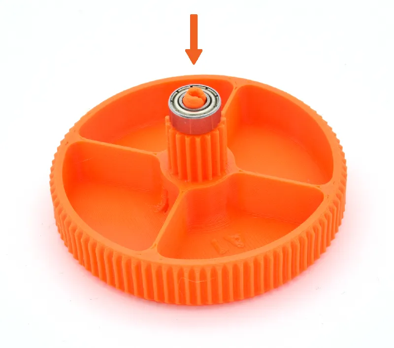 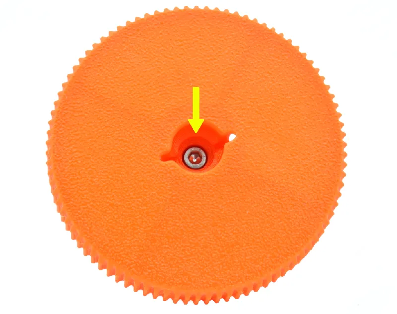 | 🟠Attach the bearing on top of the Spur-gear. 🟡Secure it with a M3x18 screw from the other side. |
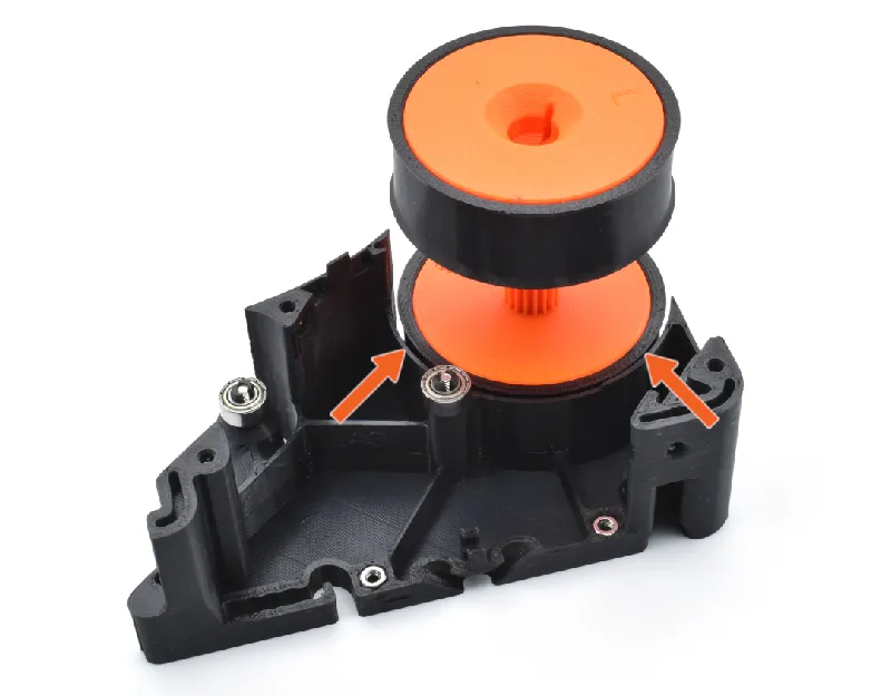
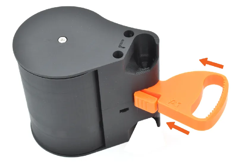
Step 11 R-Shell: Attach Spur-gear
 | 🟠Press the Spur-gear on the R-Shell's middle bearing by angling it into position. |
Step 12 Arm assembly: Parts preparation
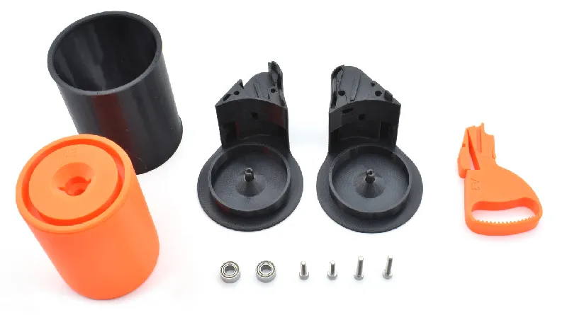 | Prepare the following items: Back-roller (1x) Back-roller-sleeve (1x) Arm-R (1x) Arm-L (1x) Ring-gear (1x) Bearing (2x) M3 hex nut (2x) M3x18 screw (2x) M3x12 screw (2x) |
Step 13 Arm assembly: Attach bearings
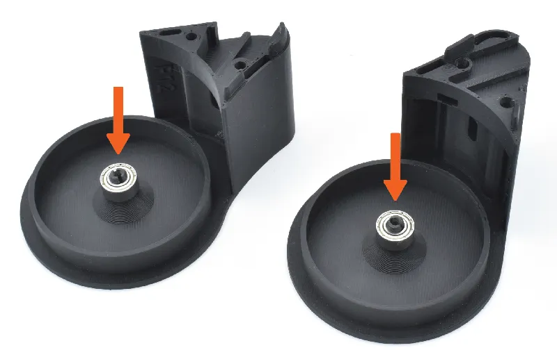 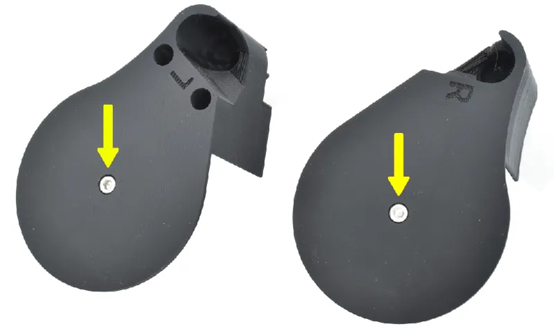 | 🟠Take the R-Arm and L-Arm and snap one bearing onto each one. 🟡Insert and tighten M3x12 screws from the back, securing the bearings into place. |
Step 14 Arm assembly: Insert hex nuts
 | 🟠Slide two M3 hex nuts into each slot on the R-Arm. Press the nuts with a hex key to ensure proper insertion. |
Step 15 Front roller assembly: Attach TPU-sleeve
 | 🟠Attach the Back-roller-sleeve on to the Back-roller |
Step 16 Front roller assembly: Connect roller
 | 🟠Push the Back-roller into place on top of the L-Arm's bearing. ⓘ The Front-roller is unidirectional |
Step 17 Front roller assembly: Attach R-Arm
 | 🟠Place the R-Arm on top of whole assembly and push it into place. |
Step 18 Front roller assembly: Insert screws
 | 🟠Through the holes on the L-Arm, insert and tighten two M3x18 screws. |
Step 19 Front roller assembly: Connect Ring-gear
 | There is a large slot in the Arm-assembly. Slide the Ring-gear through this slot, clicking it into place. |
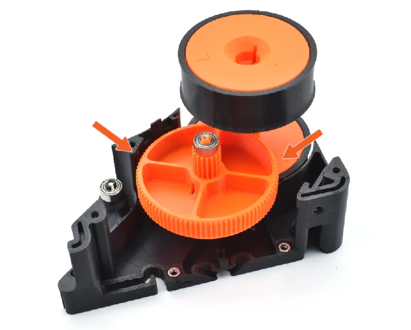
Step 20 R-Shell: Connect Arm-assembly
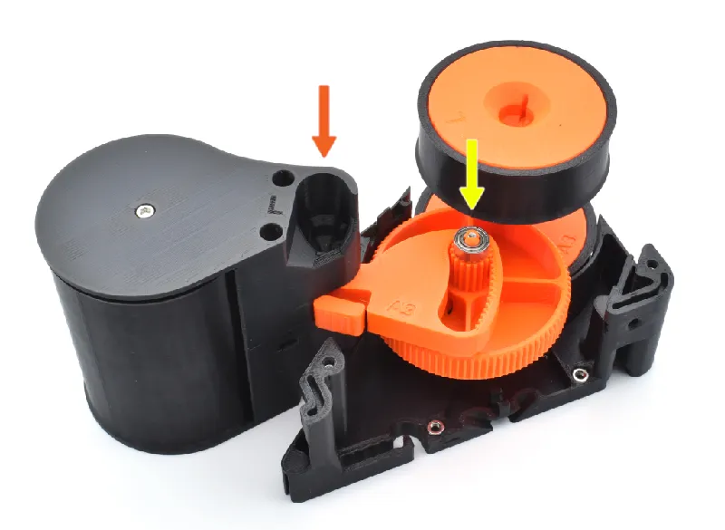 | Let's attach the Arm-assembly to the R-Shell! 🟠Align the Arm's right hole with the bearing seated on the R-shell. 🟡While doing this, rotate the arm so that the Ring-gear can freely pass the Front-roller and mesh with the Spur-gear. 🟠+🟡Press the Arm-assembly into place. |
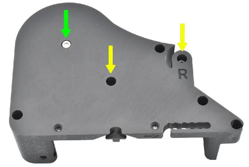
Step 21 L-Shell: Prepare parts
 | Please prepare the following items: L-Shell (1x) Bearing (2x) M3x18 screw (1x) M3x12 screw (1x) M3x10 screw (3x) |
Step 22 L-Shell: Attach bearings
  | 🟠Snap 2 bearings into place on top of the L-Shell's pins. 🟡Secure one of the bearings in place using a M3x18 screw. 🟢Secure the other bearing with a M3x12 screw.
|
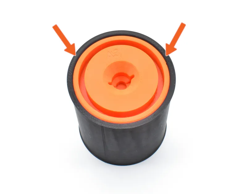
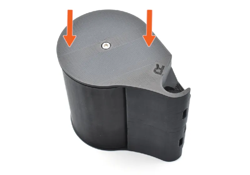
Step 23 L-Shell: Connect L-Shell
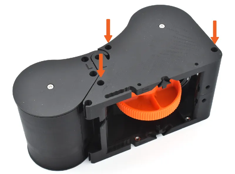 | Press the L-Shell on top of the Module-assembly. 🟠Secure it with 3 M3x10 screws according to the picture. |
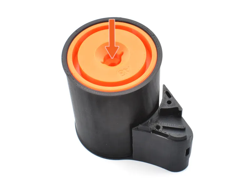
Step 24 Module assembly: Test the rewind-mechanism
 | Let's test the buffer before further assembly. 🟠 Release the arm-assembly in the uppermost position. It should slowly fall down, turning the front-roller by its own weight. 🟡Place a 1 kg spool of filament on the rollers. Roll it manually and watch as it lifts up. 🟢Release the spool very gently. It should smoothly roll back ⓘ The Buffer-module is now done. |
Step 25 Module assembly: Repetition
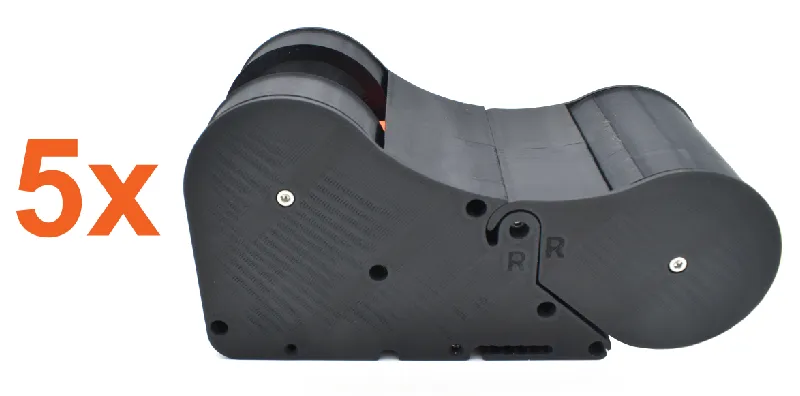 | You've assembled 1 out of 5 modules. 🟠Follow the previous steps to assemble 4 more Buffer-modules, for a total of 5 modules. |
Step 26 Main assembly: Prepare parts
 | Please prepare the following items: M3x10 screw (8x) |
Step 27 Main assembly: Connect the modules 1/2
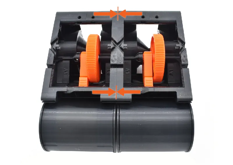 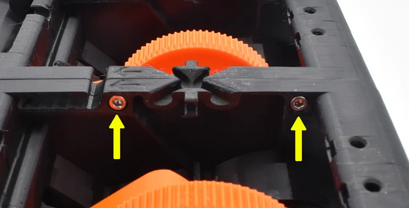 | 🟠Align two Buffer-modules with each other. 🟡Attach them with two M3x10 screws. |
Step 28 Main assembly: Connect the modules 2/2
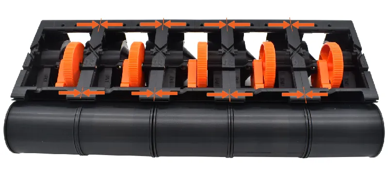 | 🟠Repeat the previous step with the other modules, connecting them all together. You're now done with with part 1 of the assembly! |
Step 29 Main assembly: Part 1 done!
  | Continue assembly for your specific setup: ⓘ The CORE One specific setup is coming in the future. The buffer can still be used for the printer, but not with specific mounting options. |
📜 Version history
Old version updates will be published here.
Update 7 April - Version A4I've gathered feedback the last couple weeks and concluded that the bearing pins needed an overhaul. Some users experienced extra friction in the mechanism, only to find out that the these pins were damaged. So here it is! Version A4 now has new strong cylindrical pins with slightly bendable parts to hold the bearings in place. I also took the opportunity and updated the Side-panel pins to also be stronger, incorporating the same kind of design. Furthermore, this version includes much higher STL-quality, allowing smoother surfaces for the Rollers. Here's a summary:
If you have any thoughts on the design or encounter any problems, please reach out to me and I will try to fix it in the next update! |
Update 30 March - Small improvementsI have implemented some things to improve printability. The “bearing-pins” are less likely to break now with stronger connections and bigger hole for the screws. R-Front-roller is also easier to print with adjusted overhangs. |
Update 27 + 28 March - Custom setups and support for COREBOXXNow you can officially install the BUFFER UNIT inside the COREBOXX. You can find the setup by clicking here! Many people have also asked if the buffer unit can be used with other printers, enclosures and MMU:s. The answer is yes, and now you can find basic STEP-files for free here to create custom brackets/mounts! They also include PTFE-guides numbered 6-12 for MMU:s with higher filament counts (like the ERCF for example). |
Update 23 March - Version A3I've been working non stop since the release last week, gathering user input from many of you. Again, thanks so much for the support! This update includes lots of improvements, the main one being the addition of TPU-sleeves for the rollers. This improves friction and makes the rewinding more reliable (special thanks to @BrianAmato_717081 and especially @LucianFlorin_1026103 for suggesting it!). Here’s a rundown of some of the improvement:
I’m now starting my work on an official Buffer Unit video. I believe I have ironed out most of the common problems some have experienced, but if you have more input please contact me and I’ll make sure to address these in the next update. In addition to the video, I’m now turning my attention to the publishing of the setups for CORE One and COREBOXX. ⓘ See part compatibility for the new version down below under “printed-parts”. |
Update 20 March - Version A2Thanks to everyone who have purchased the Buffer Unit! I'm working hard to make the Buffer Unit the best it can be. Here are some improvements:
ⓘ Old files are still available. Old Ring-gear, R- & L-Shell, R- & L-Arm and Side-panels are not compatible with the new A2 Version. |
Update 12 March - Version A1
|
Tags
Model origin
The author marked this model as their own original creation.


