BUFFER UNIT - Setup for MK4

Description
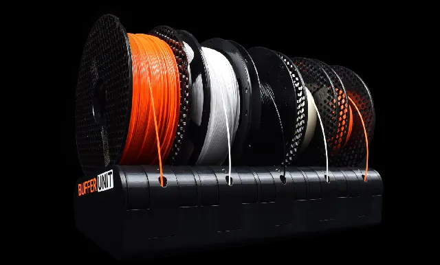
PDF| The BUFFER UNIT is a premium rewindable spool holder for the MMU3/MMU2. It's compact and easy to use, opposed to the official clunky setup for the MMU. Compatible with the Prusa MK4, MK3, CORE One, Original Prusa Enclosure and more. |
This model provides the parts & assembly for mounting the BUFFER UNIT specific for the Prusa MK4/S & MK3/S/+. It does not not contain the actual spool holders.
→ You can buy the BUFFER UNIT itself by clicking here!
Setup for MK4 & MK3
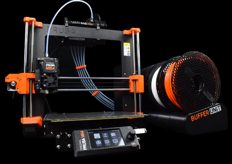
The BUFFER UNIT sits on either side of the MK4/MK3 depending on your preference. It's very easy to load filament from the side. PTFE-Tubes are routed through the inside of the units and comes out of the back side. The tubes are secured via clips and channels where the PTFE snaps in to place, making assembly easy. Read more on the store-page!

Parts List
| Item | Quantity |
| PTFE-tube | N/A |
| Stick-on rubber feet (optional, but recommended) | 8 |
Printed parts
The print files tell you how many of each part you need to print.
⚠ Note that the Side-panels are different depending on which side of the printer the Buffer Unit is mounted.
Print settings
NO SUPPORTS, 0.2mm layer height with 15% infill. PETG is recommended. See part specific settings:
R-Side-panel & L-Side-panelMulti-colored-print. The slicer will split the parts into colors once imported (3MF-file) |
Assembly Manual
ⓘ This is part 2 of the BUFFER UNIT assembly! Find part 1 here.
Tool preparation
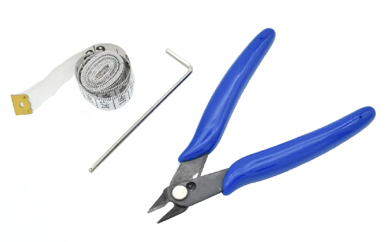 | Prepare the following tools: 2.5mm Allen key (for M3 screws) PTFE-cutter/Cutting pliers Measuring tape (for measuring PTFE-tubes). |
Step 1 Prepare the printer
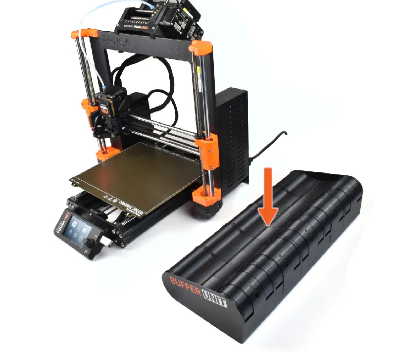
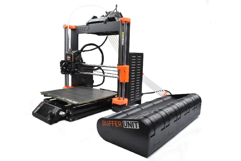 | ⓘ The BUFFER UNIT can be placed on either side of the printer. The following instructions show the BUFFER UNIT on the right side of the printer, but the same instructions apply to the left side, just mirrored. Make room for the BUFFER UNIT beside the printer. |
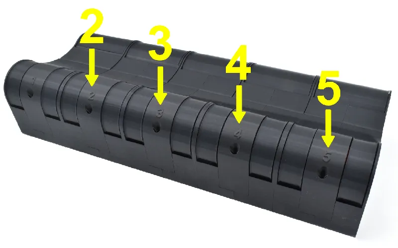
Step 2 Prepare parts
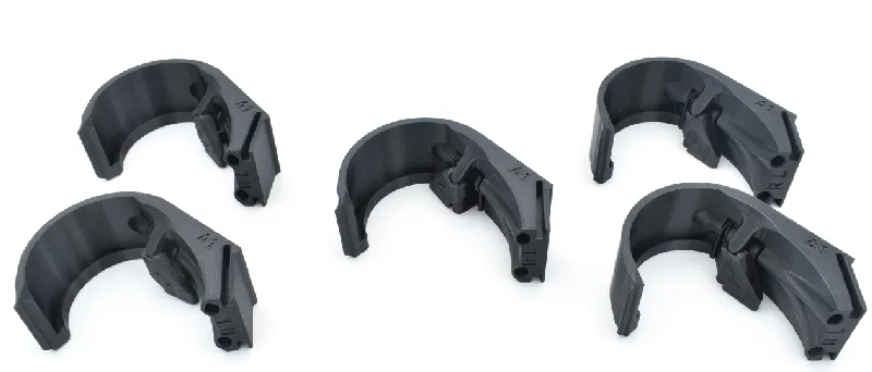 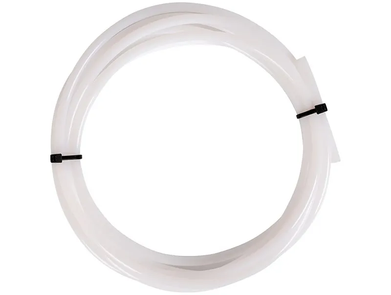 | Prepare the following items: PTFE-Tube 1-PTFE-Guide (1x) 2-PTFE-Guide (1x) 3-PTFE-Guide (1x) 4-PTFE-Guide (1x) 5-PTFE-Guide (1x) ⚠ Make sure you can move the lever back and forth |
Step 3 Connect the PTFE to the PTFE-Guides (1/2)
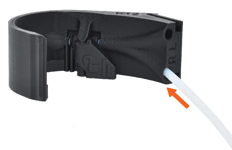 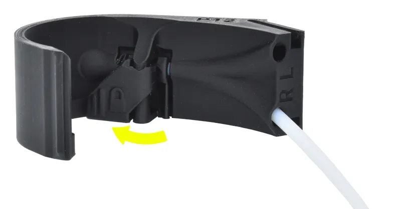 | Measure and cut a PTFE-tube to the length of xxx. 🟠Insert the tube through the right hole (R) in the 1-PTFE-Guide. Make sure it's fully inserted. 🟡Flip the lever to lock the PTFE-tube in place. |
Step 4 Connect the PTFE to the PTFE-Guides (2/2)
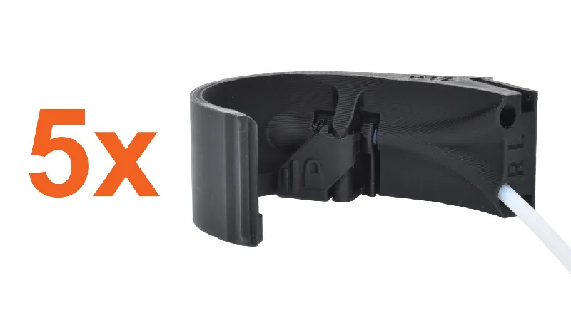 | Repeat the previous step using the following corresponding tube lengths: 2-PTFE-Guide - xxx 3-PTFE-Guide - xxx 4-PTFE-Guide - xxx 5-PTFE-Guide - xxx ⚠ For number 5, insert the tube through the left hole (L) instead! |
Step 5 Attach the PTFE-guides
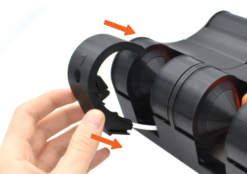  | There are slots on the front side of the BUFFER UNIT. 🟠Insert the 1-PTFE-Guide through the leftmost slot. It should snap into place. 🟡Repeat this for the rest of the PTFE-guides, inserting them in numerical order. |
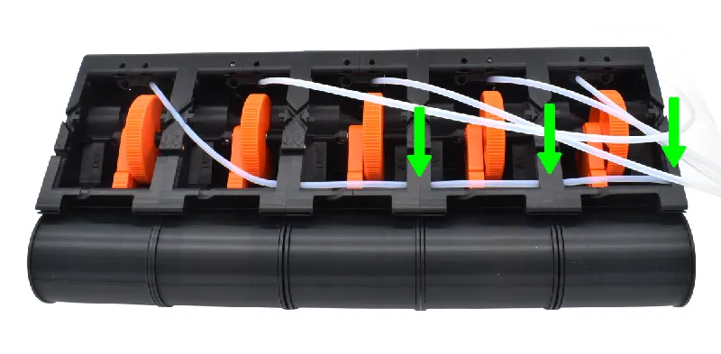
Step 6 Route the PTFE-tubes 1/4
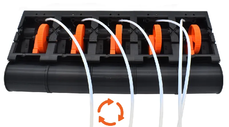 | 🟠Flip the BUFFER UNIT over according to the picture. |
Step 7 Route the PTFE-tubes 2/4
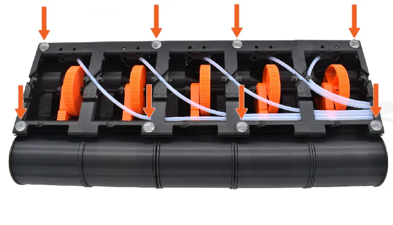
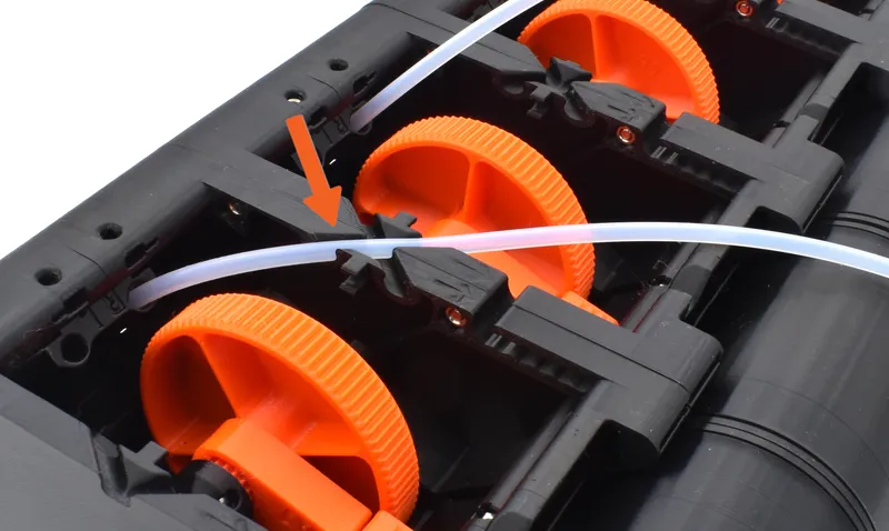 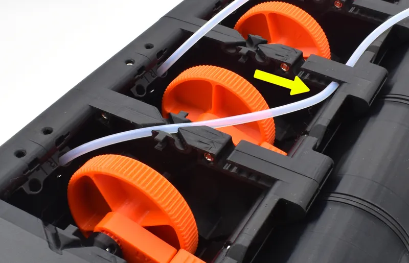  | We're now going to route the PTFE-tubes, starting from the left module. 🟠Snap the leftmost PTFE-tube onto the X-shaped slot. 🟡Guide the tube through the slot marked with an arrow. Push it all the way in. 🟢Using this same type of slot, guide the tube through the rest of the modules. |
Step 8 Route the PTFE-tubes 3/4
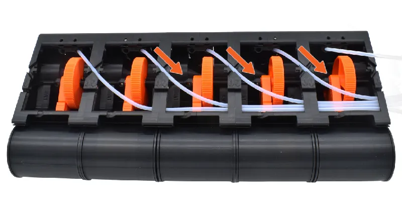 | 🟠Now, guide tube number 2, 3 & 4 like the previous step. |
Step 9 Route the PTFE-tubes 4/4
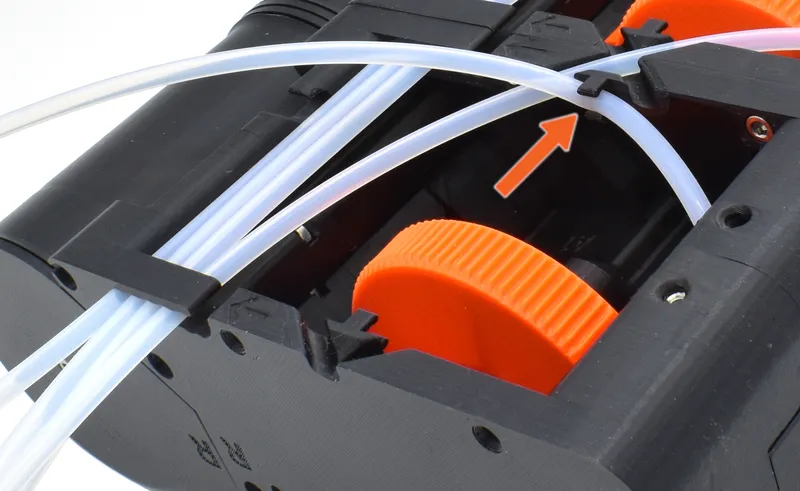 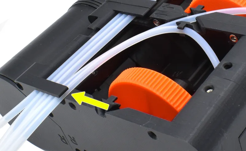 | Let's finally guide tube number 5. 🟠There's a clip next to the x-slot, snap the PTFE-tube into place. 🟡Finish of by slotting the tube beside the other tubes according to the picture. |
Step 9 Prepare parts
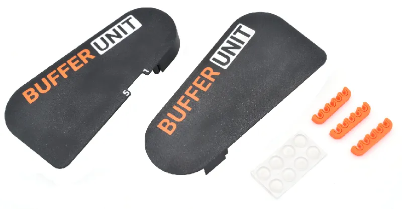 | Please prepare the following items: R-Side-panel (1x) L-Side-panel (1x) PTFE-Clamp (3x) Stick-on rubber feet (8x) ⓘ The rubber feet are optional, but recommended. |
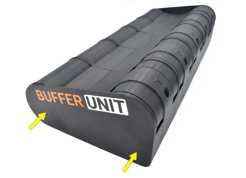
Step 10 Attach rubber feet (Optional)
 | 🟠Peel and stick the rubber feet according to the picture. |
Step 11 Attach Side-panels
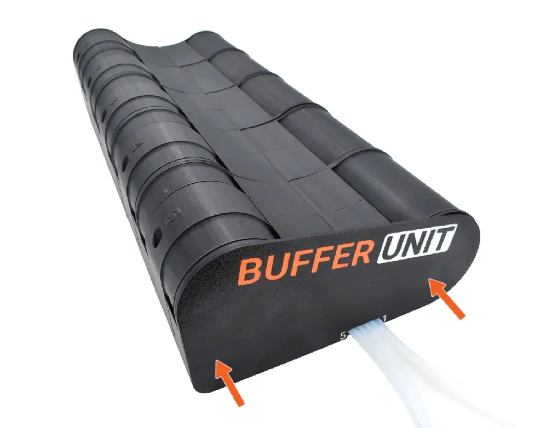  | 🟠Snap the R-Side-panel on the right side of the BUFFER UNIT. 🟡Snap the L-Side-panel on the other side. |
Step 12 Connect the MMU
  | Time to connect the BUFFER UNIT to the MMU! 🟠Place the BUFFER UNIT next your printer. 🟡Insert the PTFE-tubes into the MMU according to the corresponding MMU filament-number. |
Step 13 Attach PTFE-clamps
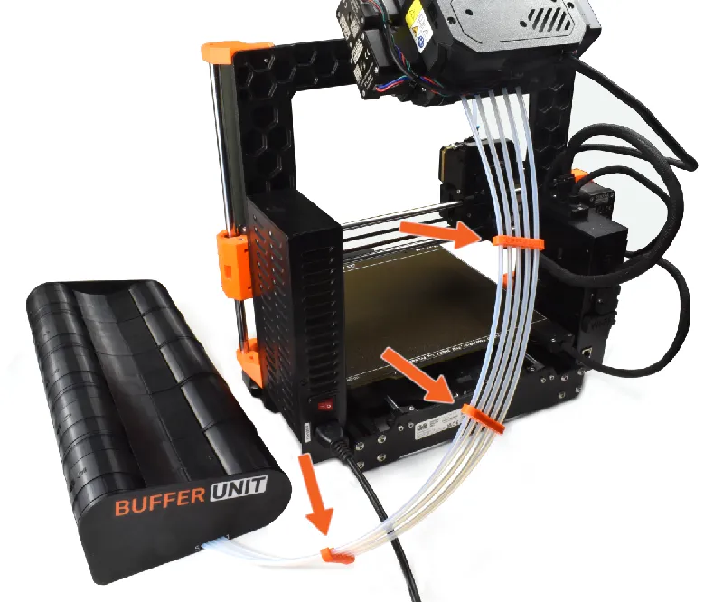 | 🟠Finally, snap the PTFE-clamps along the tubes to tidy things up. |
Step 14 Assembly is done!
 | Congrats, the Buffer Unit setup is now completed! I've never put this much work into a single project, I really hope you like it! If you like the setup, it would truly mean a lot to me if you drop a comment/make or to share the model! Tell me what you like/dislike in this google from! |
Version history
Previous version updates will be published here.
Tags
Model origin
The author marked this model as their own original creation.