Python AMS - Ultimate Bambu Lab AMS


Description
PDFNotice!
This is only compatible with the original AMS for Bambu Lab X1/P1 series.
Please follow my profile here or on Youtube or check back soon for a new design supporting AMS Pro 2, it is being worked on.
Update February 9, 2025
Python has reached version 1.05, it's the final update for the Bambu Lab X1/P1 printers.
For those using version 1.00 through 1.04 and want the latest and greatest, there is an upgrade pack you can print so you don't have to reprint everything as many printed parts have not changed since version 1.00 and all versions are indeed cross compatible.
The upgrade pack is named python-1.05-upgrade-threaded.zip. There's one for the heated inserts version too.
Changes:
- Front module and feeder module: Feeder adjustment is now fully adjustable, no set distance from the front module. The feeder modules are now attached from below for easier swapping and adjusting.
- Drive gear sleeve: Small adjustment for better gear meshing.
- Feeder module washer: New printed part.
Some older versions are available in the file archive.
Buy Python AMS
I've teamed up with a few different stores around the world offering the printed parts and everything you need for the build so you won't need anything outside of the kit:
* No printed parts included, print your own parts and buy the hardware kit and panels only.
If you're interested in the panels only for the enclosure, you can buy them from LaserFoundry.
Python AMS has a strict non-commercial license, it can only be sold with licensing through Hume Beam Engineering Solutions.
Discord Support
Please do not send me direct messages here or ask questions in the comments, I have notifications turned off as I get so many requests here and elsewhere. Instead, please join our Discord server for suggestions and technical support. Thanks!
If you need any help with the build or want to leave feedback you can join us on Discord:
Our server is named “(Unofficial) QIDI Tech 3D Printers” so don't get confused when you join as it was initially setup for that brand of printers but we've expanded it to other brands and 3D printing in general as well as channels for some of my mods, it's where I generally hang out.
Welcome!
YouTube Reviews
ModBot
RFID is fully supported now, this is an earlier review:
The Printasaurus
Troubleshooting
Gear meshing / retraction
Almost all issues reported are related to the feeder position, it's important to get this right. For most people it's just set and forget but for some the position needs to be either closer to the front roller / drive gear and for some it needs to be further away.
For version 1.05 (current): Fully adjustable for perfect gear meshing. Adjust as per the instructions below or the assembly instructions.
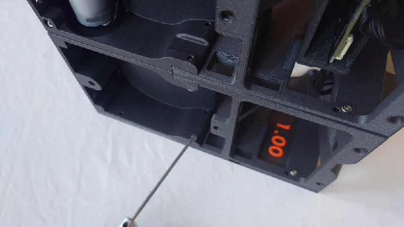
For version 1.00-1.04: There is an adjustment range of 1.0 mm front to back and around the middle position is good for most people. For version 1.00-1.03 the feeder holders are oval, while 1.04 uses feeder modules with the same adjustment range.
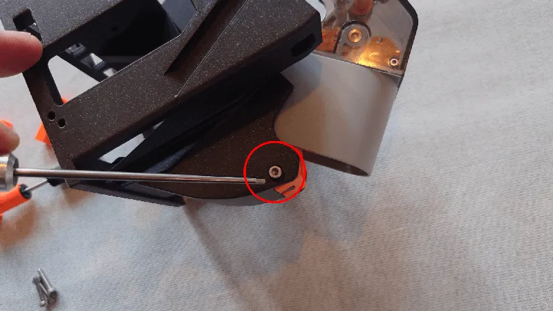
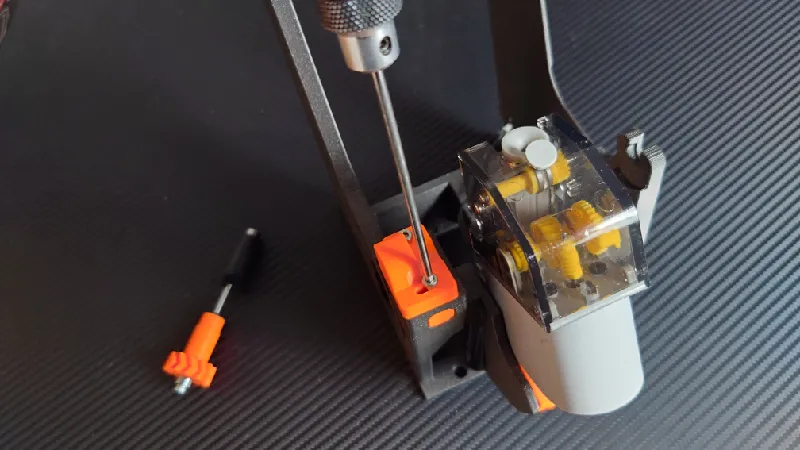
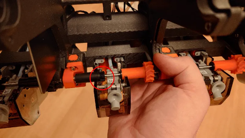
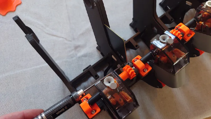
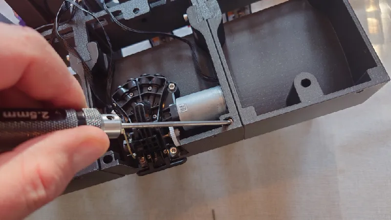
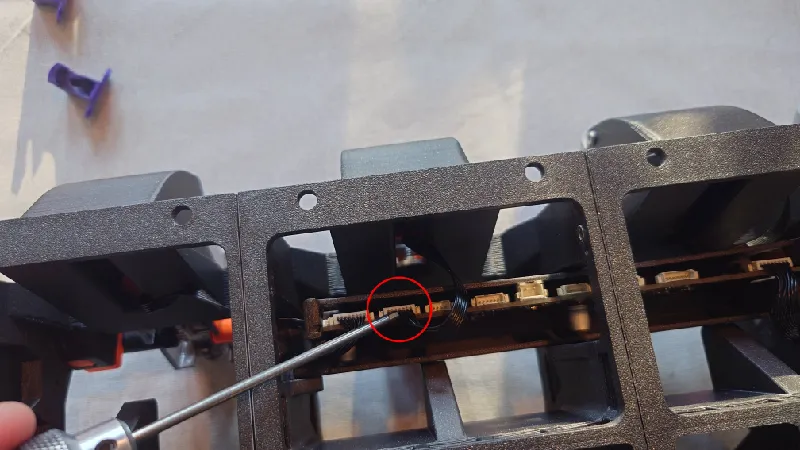
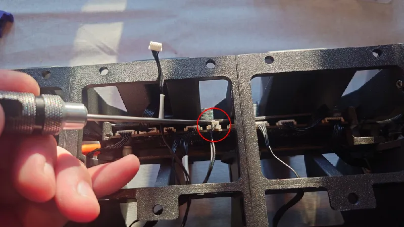
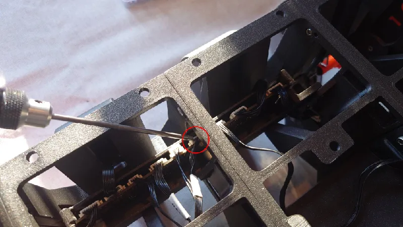
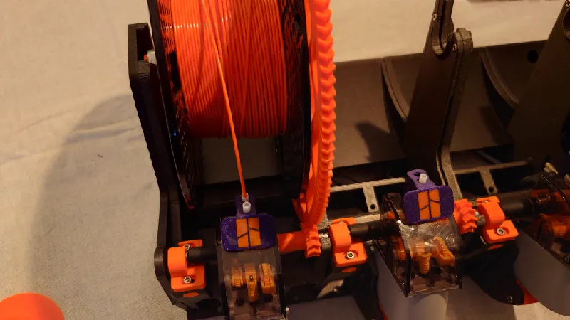
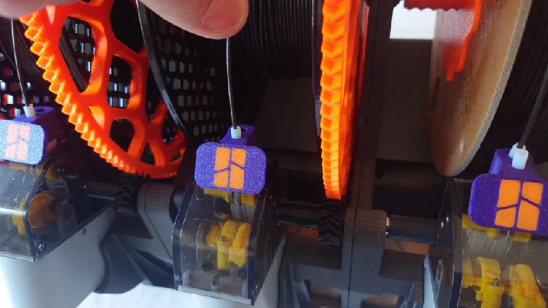
That said, a good rule of thumb is to have the feeder as close to the roller as possible without the roller grabbing the yellow gear while you rotate the roller by hand. It should not grab in either rotation. See the area circled below.
Adjust it so it just grabs it then back off a fraction:

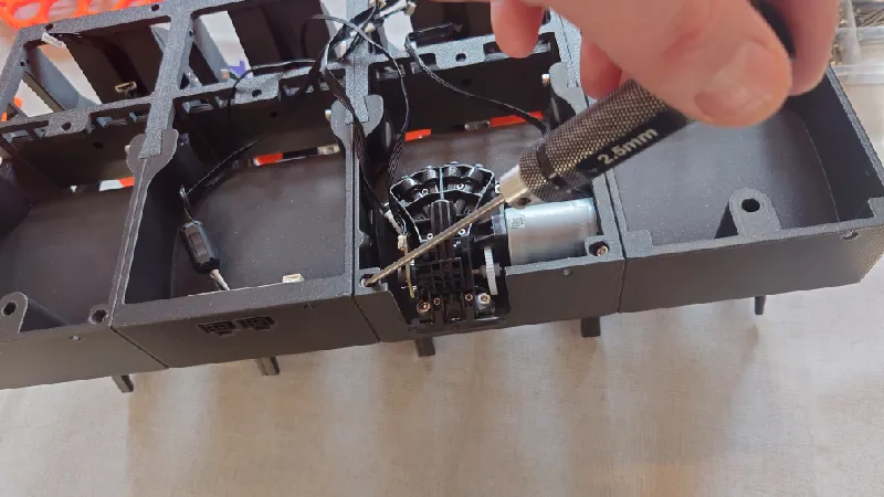
For version 1.05 the feeder modules are fastened with four screws from below.
For version 1.04 the modules attach from the sides.
For version 1.00-1.03 the feeders attach to the actual printed front module but the attachment holes are oval, allowing the same adjustment.
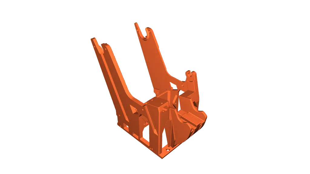
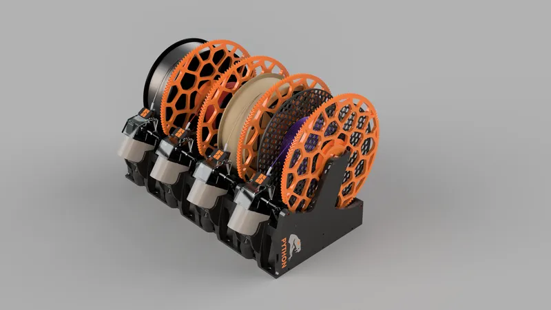
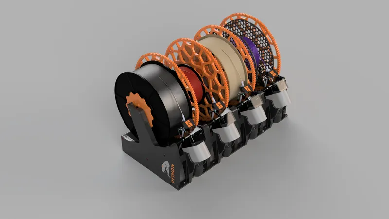
Some quick renders and a video:

Intro
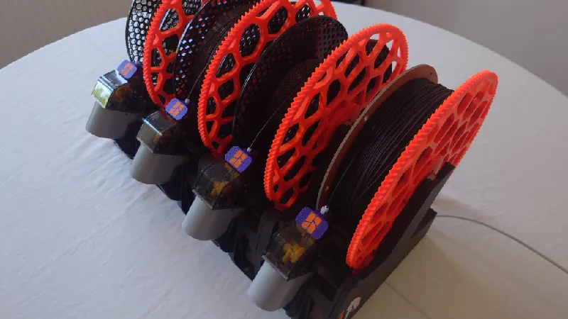
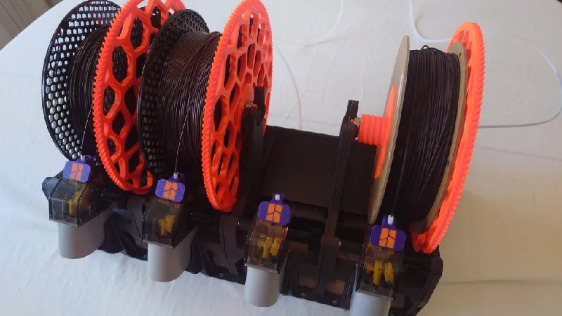
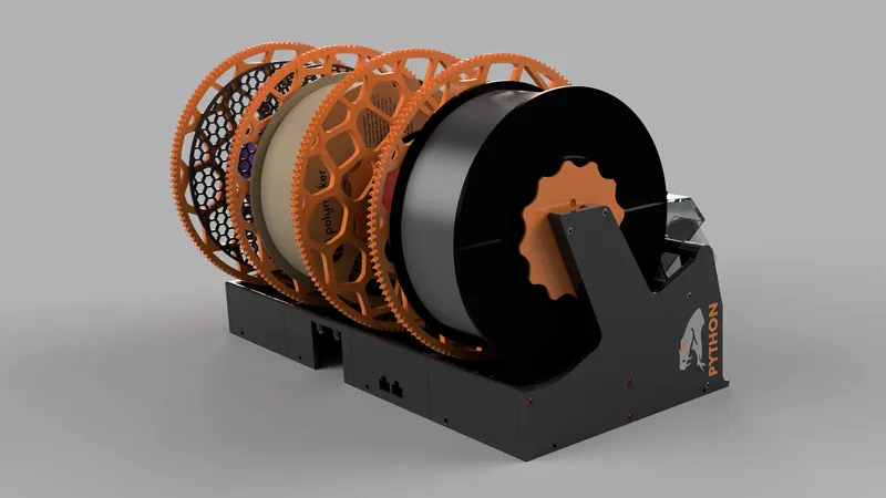
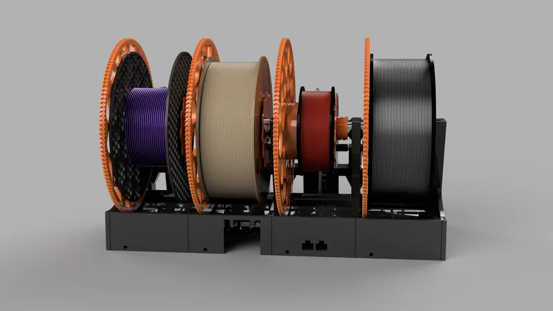
Python AMS is a highly reliable and fully modular AMS system for the Bambu Lab X1/P1 series. It can be used with two to 16 spool slots, daisy chaining AMS units is possible, just like stock AMS. The sections are joined with dovetail joints and M3 socket heads. It has a built in wall mount and the spool holders are tilted back so it can just as easily be installed on a wall.
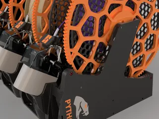
It comes with an optional but recommended enclosure that is either passively dried (like stock Bambu AMS) or with up to four active heaters (integrated Polymaker PolyDryers) that can be used while printing or when it's not in use.
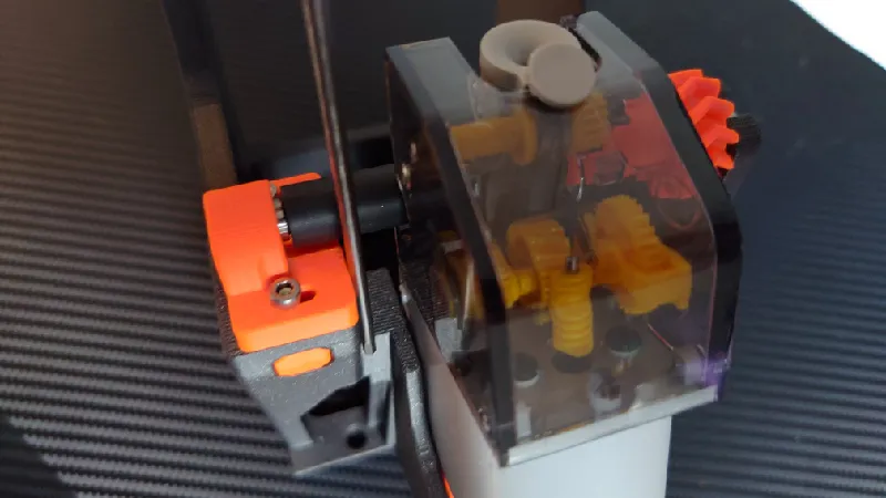
It features self-centering Double Helical gears with a high torque thanks to a 135:12 gear ratio (11.25:1) from the small drive gear on each feeder to the enlarged spool gear. It's using the Bambu AMS internals only, no modification or additional parts required apart from bearings and bolts, it's fully reversible.
No longer rely on spool weights or roller grip as the roller system is bypassed. All types of spools are supported. The spool holders can be secured with a M3 socket head against both the spool holder's threaded rod to lock it in place and also against the spool itself but in testing it has never been needed as long as they are fully tightened.
As the spools fully rest on standard 608 bearings on both sides of the spool holder, both the feeders and the AMS hub motor are offloaded, avoiding premature wear or AMS overload errors. Each slot can be used as an external spool holder for example when using abrasive filaments or for multiple printers. Or you can use four modules for a full AMS and use a fifth module on one side reserved for external spools.
Cardboard spools, refills (though a spool around it is still recommended) and various size spools are all compatible including 250 g sample spools and other odd-sized spools. Maximum spool width is around 80 mm with Python.
Python AMS? What's the story?
Some of you familiar with the Bambu Lab printers probably recognize me as the developer of Hydra AMS and Hydra PRO as well as the Vision Enclosure for the P1P.
Development of Python was started late last year but it was ramped up this spring with final testing for a little more than a month now by a team of experienced 3D printer enthusiasts and professionals close to me with over a hundred printers between us.
The name Python is again inspired by Greek mythology as I have done in the past with some of my other designs such as Hercules, Icarus, Hydra and Chimera. So it's not exactly a snake, more of a dragon-like creature that Apollo fought. :)
With Hydra I did as much as I could to maximize spool compatibility while maintaining high reliability but was limited with the size of the AMS box and the roller system which can be finicky at times and not without issues.
With Python it was time to think outside the box. The trend of more and more cardboard spools as well as refill and odd-size spools on the market I felt it was time to make an ultimate AMS system. Not only to support all kinds of spools but also as an actively heated AMS drybox with a styling matching the Bambu printers. You can also use it without any enclosure if you like or with a passive drybox without heaters (same as stock AMS).
The main changes / improvements over the standard AMS:
- Compatible with all types of spools and sizes, up to around 80 mm wide.
- All spool diameters fit, from tiny sample spools up to 210 mm diameter spools.
- External spool function (bypasses the AMS) possible for all four spool slots.
- Actively heated enclosure with up to four heaters (optional).
- No need for spool weights.
- No need to rely on roller grip or worry about stuck spools.
- High torque self-centering double helical gears.
- Fully supports RFID in all spool slots.
- PTFE Load Buttons to both save the funnels and improve ergonomics (optional, it's a separate download).
The main Python AMS step files are not available publicly, please don't ask.
FAQ and Technical Specs
“Does this work like an AMS?”
- Absolutely, it works just like the stock AMS except the spools are sitting in spool holders, driven by double helical gears rather than on top of rollers. This highly increases the reliability and versatility.
“Can I use multiple Python AMS?”
- Absolutely, you can daisy chain up to four of them for a 16 spool AMS.
“Can I hot plug an AMS to a printer?”
- Normally this works fine but to be sure please shut down your printer before plugging in Python AMS (or a stock AMS for that matter!), it is much safer for the electronics. It avoids electricity spikes that can potentially happen if there is a poor connection between the AMS bus cable (black cable from printer to AMS) and the AMS power board, which in turn can damage the AMS main board.
- Hot-plugging can actually damage the electronics (AMS main board) so plug everything in before you boot up the printer.
“Do I need a stock AMS?”
- Yes. You use those parts and transfer over to Python. All of the parts can be bought individually but it might be cheaper to just get an AMS rather than sourcing the parts individually, I haven't compared the prices.
“How large is Python AMS?”
- Due to the individual spool holder system with side placed bearings and also to support wider spools, it's a bit larger than a stock AMS. It's a downside. But we trade size for very high reliability. However, Python is modular so you can use for example three modules only to slim it down. But for a full four spool setup the dimensions are: 439.20 mm (width) x 310.00 mm (depth) x 275.00 mm (height) including spool holders and front feeders (full install). Each module adds or subtracts 106.5 mm from the width.
“Can I place Python AMS on top of the printer?”
- While you can do this it will stick out a bit on each side as it's about 50 mm wider than the printer itself. I recommend placing it next to the printer or wall mounting it.
“Do I need to use an enclosure?”
- It depends on which material you print, how long your prints are and the humidity of where you live. It doesn't have to be a fancy enclosure, you could just stick it in a large airtight container and drill holes for the PTFE tubes and cables, it works just as well. However, filament is always best when dried and the ideal setup is an Actively Heated Enclosure.
“What is the size of the enclosure?”
- The size of the enclosure is 460.0 mm (width) x 390.5 mm (depth) x 293.0 mm (height).
“Does it support RFID tags?”
- Since version 1.02, Python fully supports the Bambu Lab spool RFID tags.
“One feeder does not engage / disengage the front roller.”
- This is almost always due to a misalignment of the feeder.
- Make sure you use 2.5 mm ID (inner diameter) PTFE tubing as per the BOM, if you use standard 2.0 mm ID it can be too tight.
“Can I use “AMS Savers / Filament Guides" with Python?”
- Absolutely, all AMS Savers and so called Filament Guides are supported.
“Can I get the source design files in step format?”
- The main Python AMS step files are not available publicly. However, some files are available in step format, please view the remix tab.
BOM - Bill of Materials
You can print Python AMS in just about any filament you like. However, if you plan on keeping the AMS directly on top of the printer it's best to print it in PETG as the heat from the printer can soften the printed Python parts if they are printed in PLA for example.
For this reason and for reliability I recommend placing the AMS next to the printer or wall mounting it.
Around 1.8 Kg of filament is required at the recommended print settings for the full build including four spool holders.
I've printed most of the test builds in Prusament ASA, PLA and eSUN PLA+, both brands and filament types work great. PETG is also a great option.
Filament
Fasteners
You need quite a few M3 socket heads but you don’t have to use them in all screw locations if you don’t want to. However, here is a list of all screw locations and specs:
- Left side panel against first module: 3 x M3-16 mm plus 4 x M3-8 mm
- First module against left side (inside out, optional): 1 x M3-12 mm
- Front modules against each other: 12 x M3-8 mm
- Fourth module against right side: 4 x M3-8 mm plus 2 x M3-16 mm
- Right side against fourth module: 1 x M3-16 mm
- Rear modules against front modules: 6 x M3-25 mm
- Rear modules against each other: 3 x M3-25 mm
- Four front roller sleeves: 4 x M3-10 mm
- AMS filament hub / motor: 4 x M3-12 mm
- Four spool holders: 20 x M3-25 mm
- Attaching the main PCB holder: 2 x 8 mm
- Four adjustable feeder modules: 16 x M3-16 mm
- Four adjustable front roller holders: 8 x M3-16 mm
To summarize, the following M3 socket heads are needed:
- 22 x M3-8 mm
- 4 x M3-10 mm
- 5 x M3-12 mm
- 30 x M3-16 mm
- 29 x M3-25 mm
You don’t have to use screws in all screw locations if you don’t want to.
If you don't have any at home it's best to grab the kit below, it will have everything you need for this build and more:
Bearings
For the spool holders you also need 8 x 608-ZZ bearings:
You also need 4 x 693-ZZ bearings for the front drive gears sleeves. You could use the bearings that came with your AMS (for the rear rollers, pull them off) but a set of 10 bearings is cheap and you don't need to pull them off, possibly damaging them:
PTFE tubes
You need about 1.5-2 m PTFE tube to cut to length. I recommend the stock Bambu PTFE tube which has an inner diameter of 2.5 mm and an outer diameter of 4.0 mm. Go for the AMS Hub / Custom Cut which is a single piece 4 m tube.
Optional
I highly recommend these Nano Coated Helical Extruder Gears from FYSETC, I use them for all my Bambu printers, they're inexpensive and offer a number of improvements of the stock gears:
I've also heard great things of the new BigTreeTech Panda Extruder but I've not tried it personally yet, you can get it including the Revo hotend as well:
Although not required these PEO/PEI/PEY bed sheets are great, I have most options myself, it gives a quite cool look on the first layer. There are a few shops offering different plates:
- Build Plate PEO/PEI/PEY Spring Steel Sheet (Super 3D)
- Build Plate PEO/PEI/PEY Spring Steel Sheet (IdeaFormer)
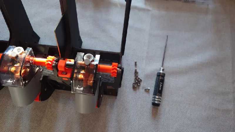
The Hex Tools are superb for any 3D printer, I've had mine for years. They are particularly useful for the Python assembly.
Tools
I'm using a simple tool for cutting the PTFE tube, you can use a knife as well. I also use a fine file for cleaning up the parts. And if you go for the optional heated inserts, a soldering iron is needed. A short hex key for 2.5 mm is useful as well.
For the heated inserts version, install a short M3S heated insert in all spots with a crossmark, you need about 60 of them.
Warranty
Python AMS does not void your warranty but be careful, especially with the AMS main board, use an antistatic wrist band. Although the mod is completely reversible and you can't tell the parts have been installed in Python AMS, I take no responsibility and you're on your own. Be careful and take it slow, read this page twice before you start.
Support
All my designs and mods on Printables are free to use and remix. They have a non-commercial license. If you enjoy this or any of my other designs you can send me a small donation using the link below. Thanks :)
https://www.paypal.me/humebeamengineering
If you prefer Crypto/BTC you can send me a message.
If you send a donation be sure to mention Python AMS in the comments box and you will be added to the list below.
Official Supporters
If you have donated $5 or more you will be added to a list of official supports as a thank you from me and you will also be assigned a serial number, the list will be updated as often as possible.
Read more and get the custom printed parts with your serial number here:
Thanks again!
If you want to remain anonymous, leave a note with your donation. If I've missed your donation let me know.
Before Printing Python AMS
Make sure you dial in flow correctly before you start so that you are not overextruding. The problem then is you can't join the dovetail joints and assembly properly.
The Bambu Lab printers usually do a pretty good with automatic flow calibration but it's best to confirm flow anyway, sometimes it is inaccurate. There are ways to do manual flow calibrations directly from Bambu Studio and Orca Slicer so you can use those.
Once you have done that, print these dovetail test joints, more info here:
Earlier Versions
There are some earlier versions available in the file archive.
Print Settings
All parts print without supports and I recommend using 3 walls and an infill of around 15%. Print all parts in the direction I have set them.
There are individual 3mf files posted or you can download one of the full sets:
- python-ams-1.05-full-set-abs.3mf
- python-ams-1.05-full-set-asa.3mf
- python-ams-1.05-full-set-petg.3mf
- python-ams-1.05-full-set-pla.3mf
- python-ams-1.05-full-set-pc.3mf
All parts: Aligned seam position.
These can be loaded in Bambu Studio or you can print them directly from Bambu Handy.
Main parts:
- front-module-print-4pcs-1.05.3mf
- feeder-module-threaded-print-4pcs-1.05.3mf
- feeder-module-washers-print-8pcs-1.05.3mf
- roller-block-threaded-print-4pcs-1.05.3mf
- drive-gear-sleeve-threaded-print-4pcs-1.05.3mf
- drive-gear-holder-print-4pcs-1.05.3mf
- main-pcb-base-print-1pc-1.05.3mf
- left-rear-print-1pc-1.05.3mf
- motor-rear-print-1pc-1.05.3mf
- pcb-rear-print-1pc-1.05.3mf
- right-rear-print-1pc-1.05.3mf
Tip: The drive gear sleeves can be printed in TPU 95-98A (tested by me) for a much more silent operation but normal “hard” filament is fine too but will be louder when it's switching spools.
Sides:
- left-side-print-1pc-1.05.3mf
- right-side-print-1pc-1.05.3mf
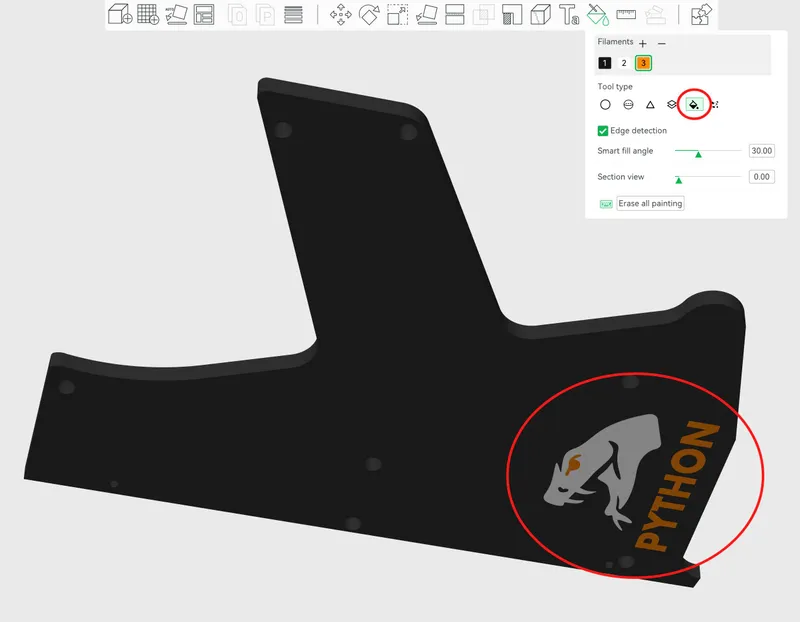
If you're an offical supporter, download your custom left and right sides here:
For these parts the Python logo and text is “hidden” in the first layer. Here you can use the Paint Bucket tool to paint the logo and text:
Spool holders:
- m3-wafer-head-gear-side-print-4pcs-1.05.3mf
- m3-wafer-head-top-side-print-4pcs-1.05.3mf
- spool-gear-135t-print-4pcs-1.05.3mf
- spool-holder-bottom-print-4pcs-1.05.3mf
- spool-holder-top-print-4pcs-1.05.3mf
- threaded-rod-print-4pcs-1.05.3mf
Use dry filament.
Optional Prints
These prints are optional but recommended to accompany Python AMS:
- Python AMS - Adaptive Spool Holder
- Python AMS - PTFE Load Buttons
- Python AMS - Silica Gel Box
- Python AMS - Actively Heated Enclosure
- Python AMS - Passively Dried Enclosure
- Python AMS - TPU Riser
- Python Refill Spool
Assembly Guide
Please view the assembly guide PDF for your version of Python, they are very similar but there are some differences in the feeder and drive gear mounting.
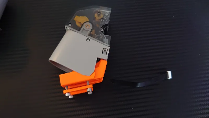
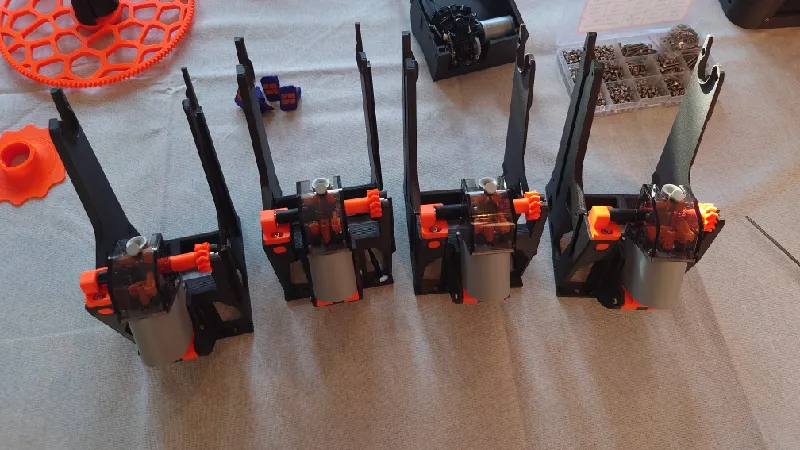
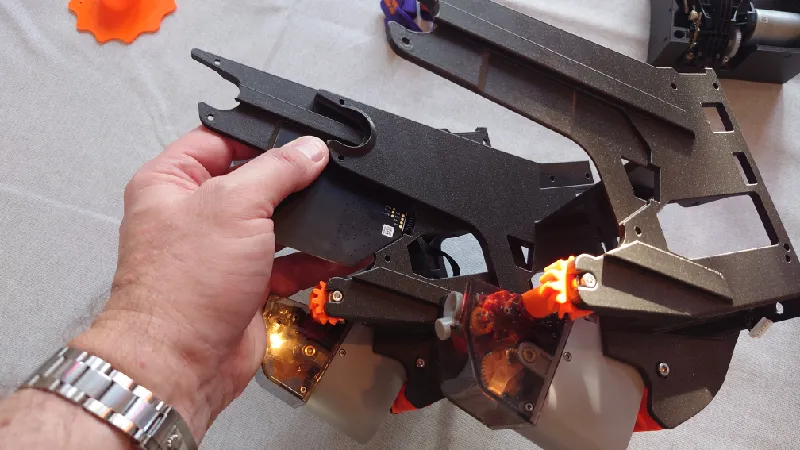
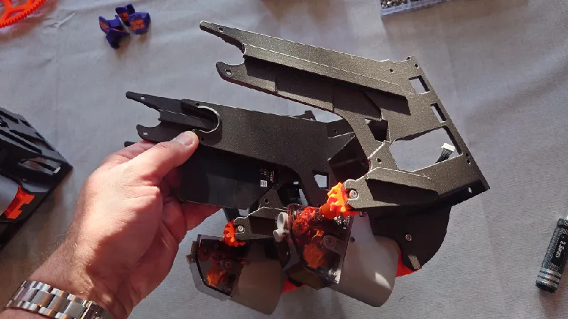
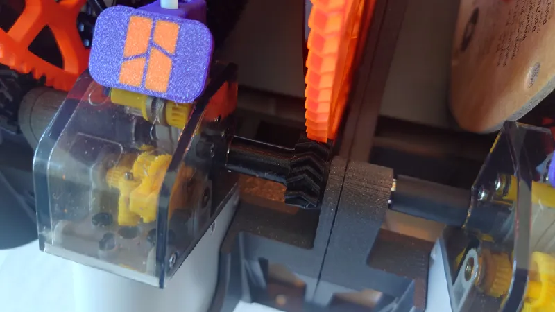
If your front modules look like this, you use the current version (1.05):
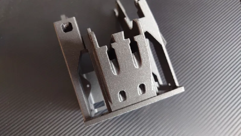
- If your version look like the one above, follow the assembly instructions below or view python-assembly-instructions-for-python-1.05-compressed.pdf
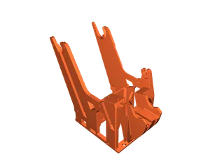
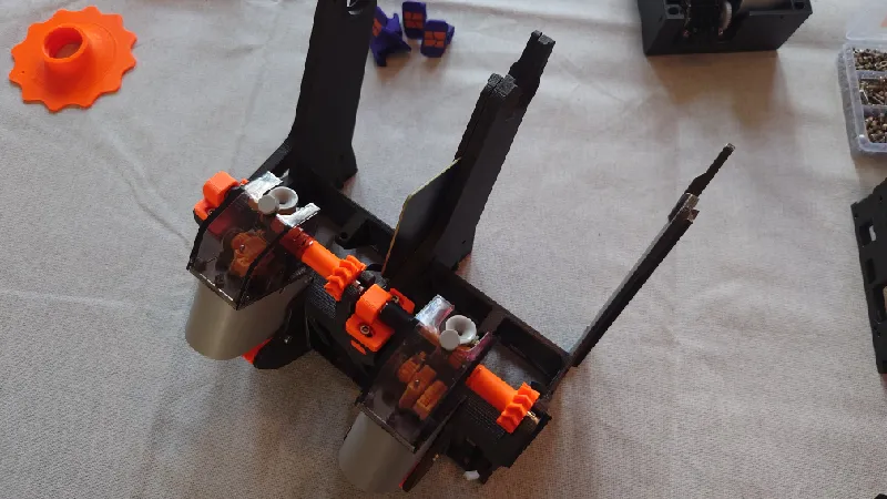
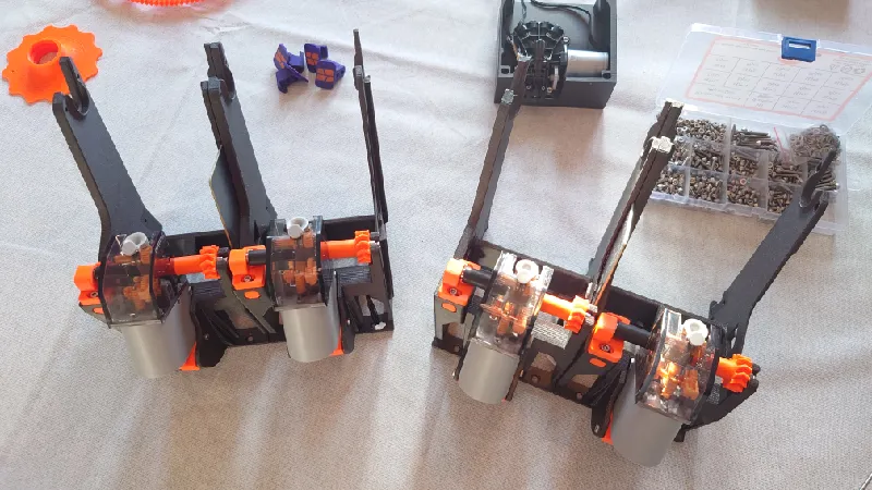
Else, if you use an earlier version, identify yours below:
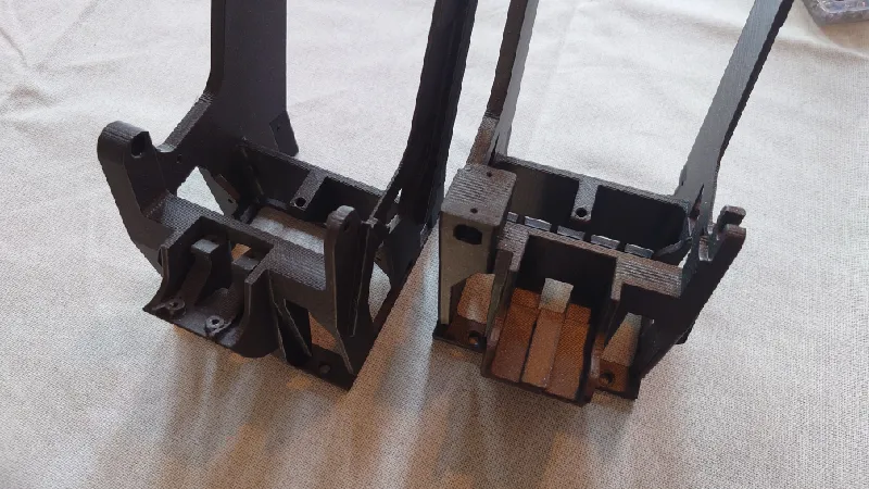
- If your version look like the one on the left, view python-assembly-instructions-for-python-1.00-1.03-compressed.pdf
- If your version look like the one on the right, follow the assembly instructions below or view python-assembly-instructions-for-python-1.04b-compressed.pdf
Assembly Instructions
If you've used Hydra before you should be familiar, it's very similar.
Remove the Bambu Lab AMS internals from the standard AMS, follow this guide, it's not difficult:
https://wiki.bambulab.com/en/x1/maintenance/replace-the-ams-main-frame
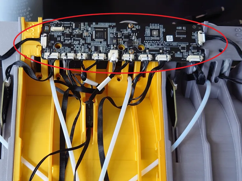
Be sure to mark all cables and connectors before you remove them. I recommend marking each connector on the board and corresponding cable with a thin permanent marker pen as pictured below:
Precaution: Always wear an antistatic wrist band when working with electronics.
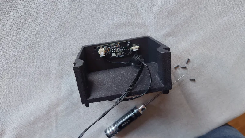
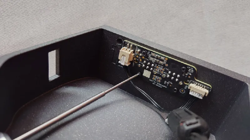
You should also remove the small rear PCB from the AMS box, it sits with four small black screws. Take the board and the screws, they're needed for the Python build.
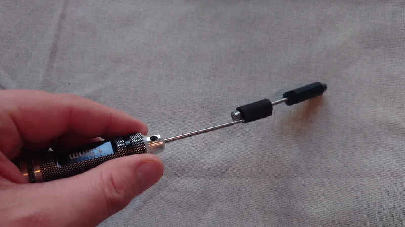
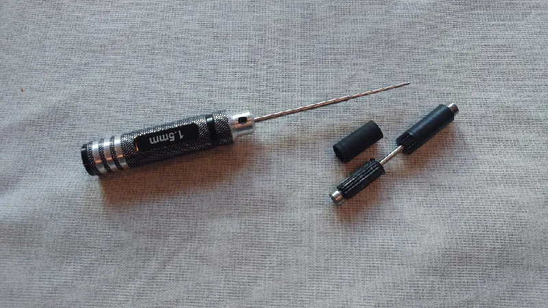
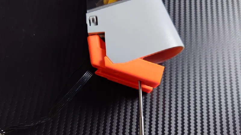
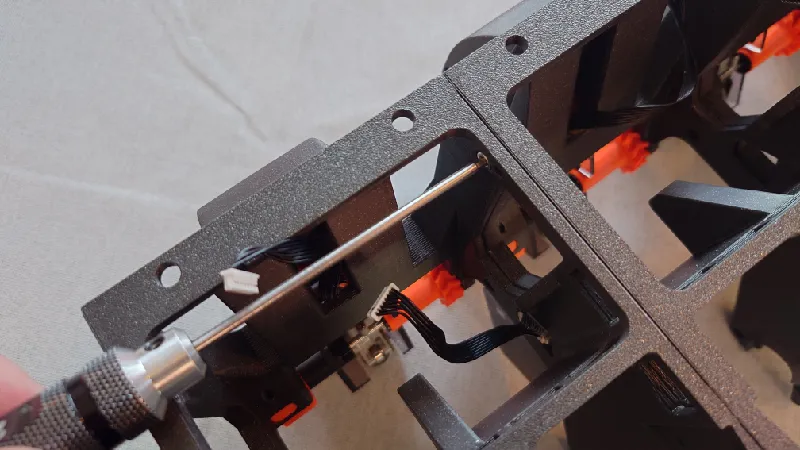
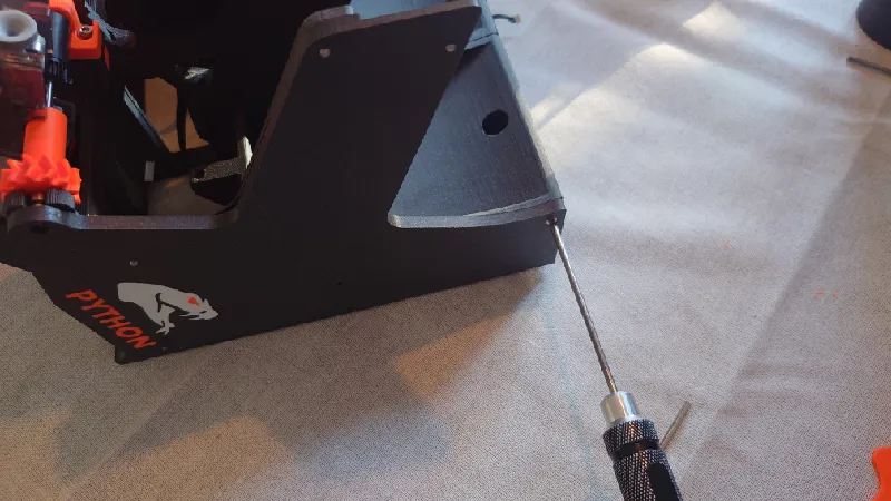
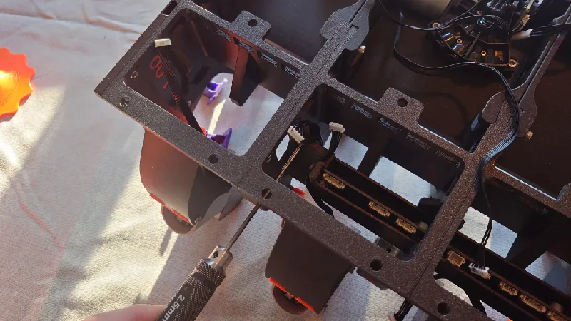
Once that is all done, the first step is to remove the rubber sleeve from the passive side of the front rollers, meaning the side without the gear. Do this for all four front rollers.
It's very easy. Just insert a thin pin between the rubber and the plastic casing and rotate the pin all around it. I'm using my 1.5 mm hex tool, it takes less than 30 seconds to do one. Save the rubber sleeves in case you revert to stock later.
Front Rollers
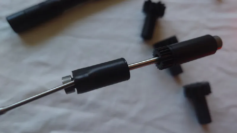
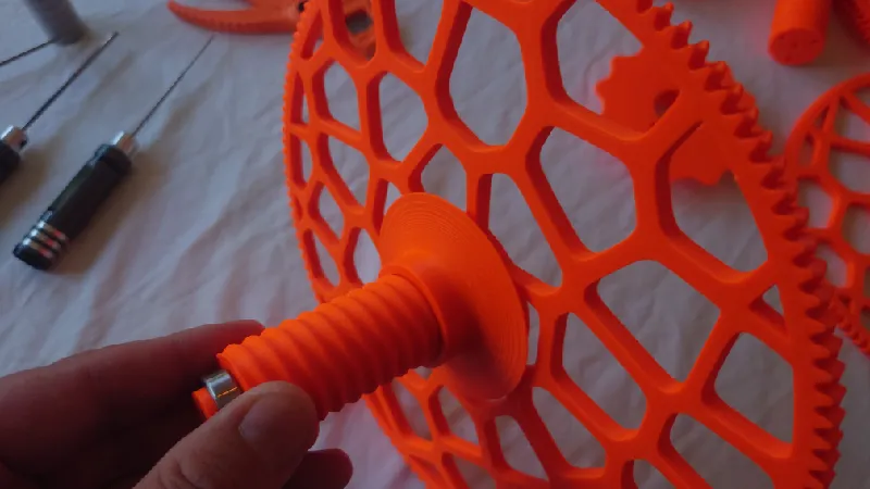
Continuing with the front rollers, grab the front roller sleeves and install it by pushing it fully in. It's a good idea to hold the plastic casing so it doesn't slide off the steel shaft as it's just pressed on.
Pictured here is my roller sleeve printed in Prusament ASA but it's a good idea to print them in TPU as Python will run much more silent than hard filament.
You shouldn't need to use any glue but if you want to, use silicon glue that's non-permanent.
Take a 10 mm M3 socket head and a small 693-ZZ bearing and screw these to the front roller sleeve:
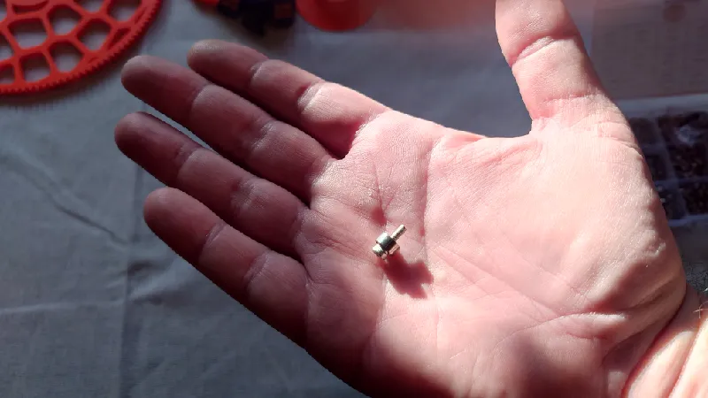
Screw it in fully then back off a quarter of a turn so it spins freely.
For the heated inserts version it uses a heated insert here instead.
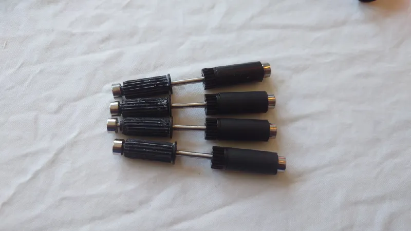
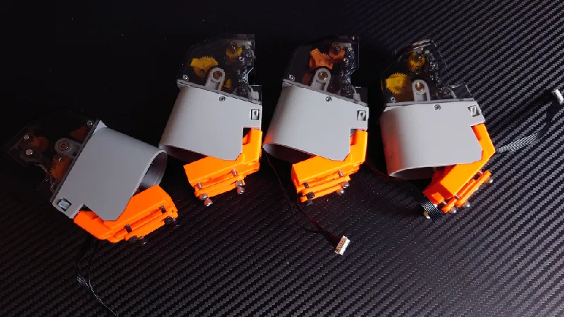
Now you should have a set of four front rollers and the Python drive gear sleeves installed.
AMS Main Board
The next step is to insert the main AMS board into the holder (main-pcb-base-print-1pc-1.05.3mf). Take notice of the board direction.
It's just friction fit. Make sure to press down both sides at the same time so it doesn't get inserted at an angle because then you will have issues pressing it fully in. If it sits too loose you can secure it with a dab of silicone glue.
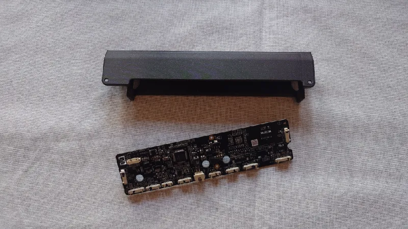
PCB Module
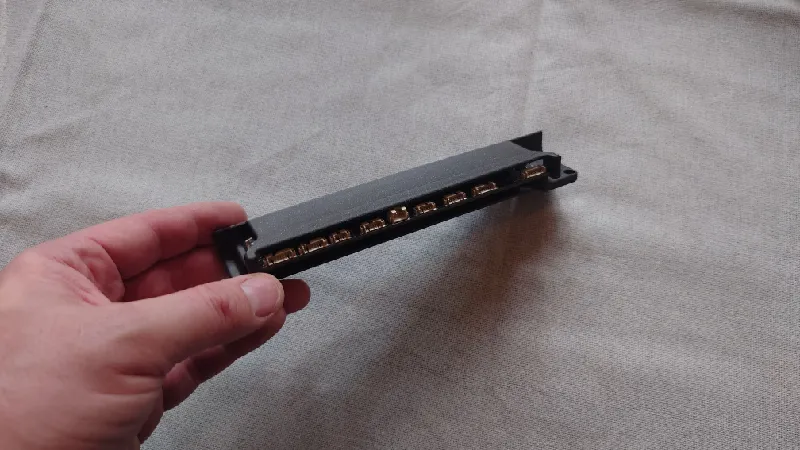
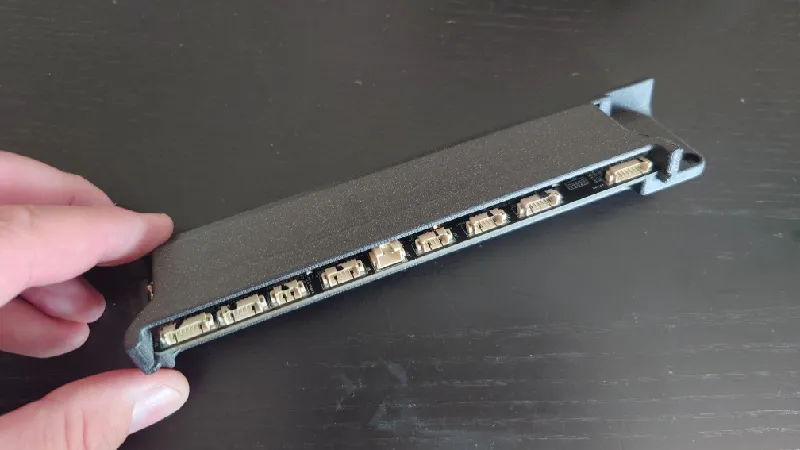
The next step is to screw the small rear PCB to the PCB module (pcb-rear-print-1pc-1.05.3mf). Use the same four screws that attached it to the stock AMS box.
Take notice of the board direction, the cable connectors should face the “roof” of the printed part. The ferrite core (black round plastic container) you should just leave “hanging” in the air, there is no socket for it and it's not needed.
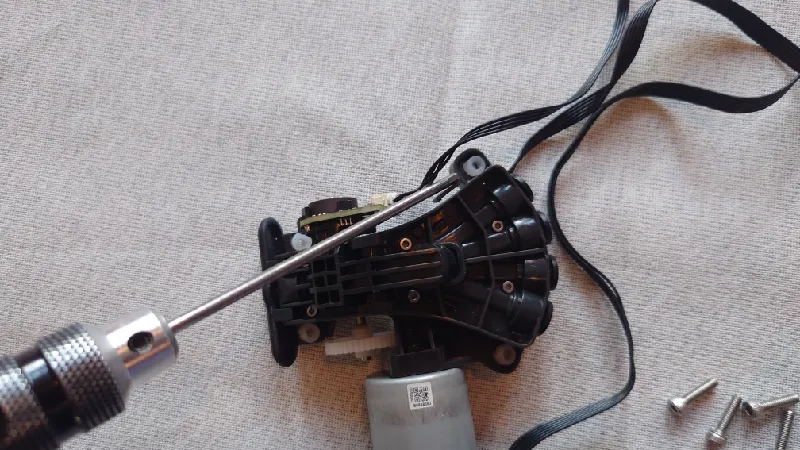
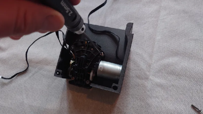
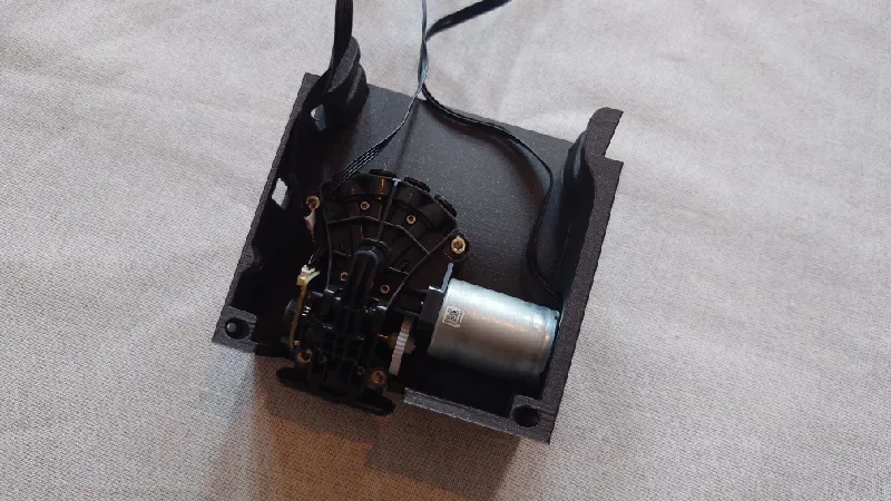
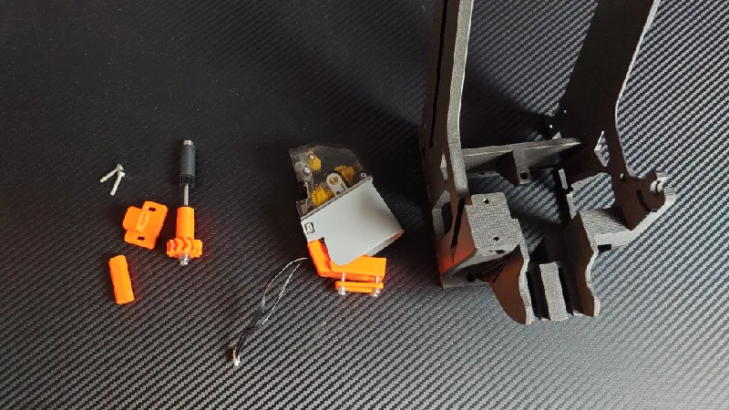
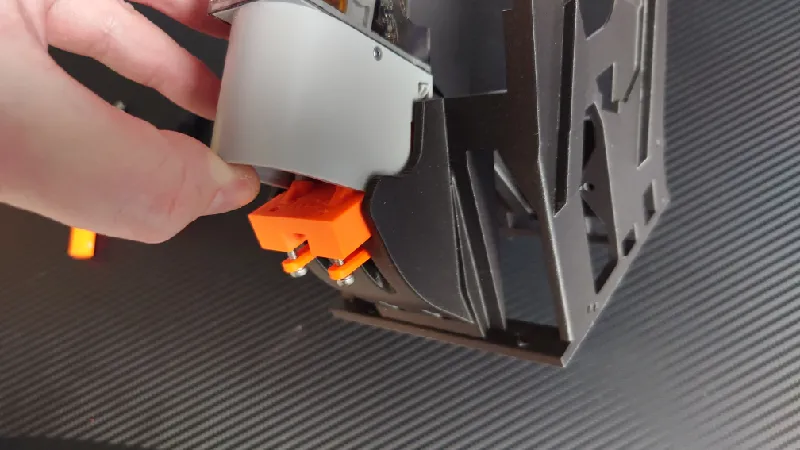
Motor Module
Next, mount the motor / AMS filaments hub motor. Remove the four stock screws and install it in the module with four M3-12 mm socket head screws. You can keep or remove the white rubber bushings, it doesn't matter.
Feeders
Next it's time to install the four feeders in the feeder modules. Use the four stock black screws for each one.
Next, use four M3-16 mm socket heads with the feeder module washers in between. The chamfered side of the washers should face the feeder.
Do not fully screw the socket heads in, leave a gap of around 6-8 mm so they can be slid into the front module later before being tightened.
Do the same for all four feeders.
Spool Holders
Unlike the stock AMS where the spools run on top of rollers, Python uses spool holders that are compatible with all sorts of spools and it uses geared delivery for high torque. The spool holders are compatible with an inner diameter / hole diameter of the spools between 38 and 85 mm, which is probably 99% of all spools.
But if you have even bigger inner diameter of your spools it's no worry, there are step design files available of these (check the remix tab) so you can make your own.
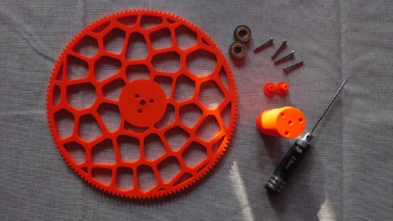
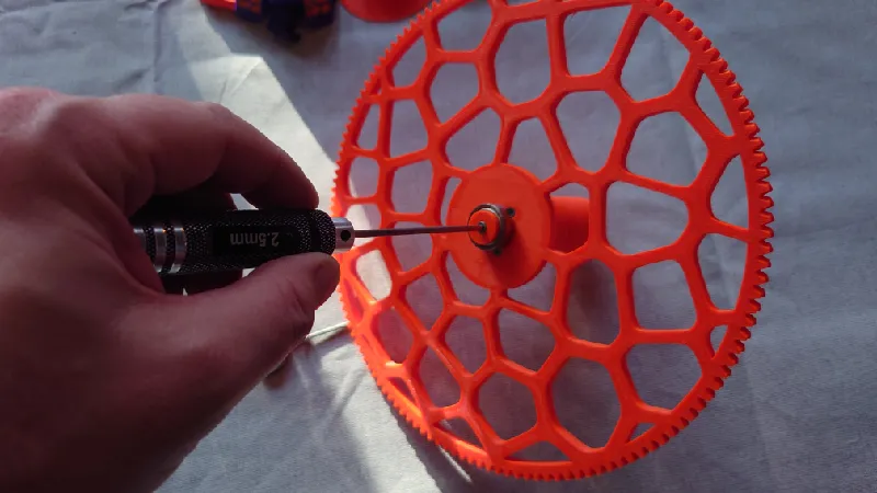
Start by screwing in the three outer M3 socket heads. The length isn't very important but around 25 mm is good. Have them go through the spool gear by a few mm so it's easier to align with the threaded rod. Then just screw it fully to the threaded rod (not pictured).
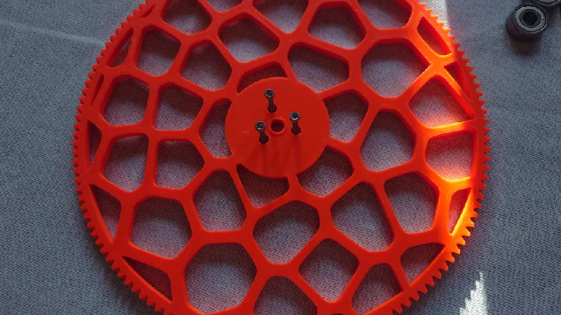
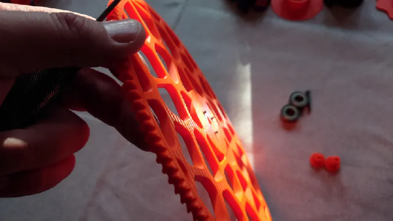
The next step is to attach the 608-ZZ bearings using the printed parts and M3 socket heads. The taller “wafer head” goes on the spool side (m3-wafer-head-gear-side-print-4pcs-1.05.3mf) and the shorter wafer head goes on top of threaded rod.
The reason it's taller is it goes through the spool gear as well which is 6 mm thick.
Do the same with the top side of the threaded rod.
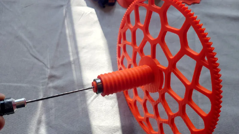
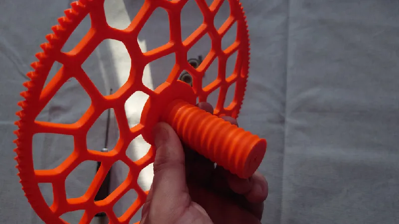
Next, screw on the bottom of the spool holder. This part is important to keep the spools centered on the spool holder but it's also important so that when you install a spool and tighten it, you tighten (mostly) against the rod and not just the large spool gear (thus bending and deforming it).
If you use small sample spools or other very narrow spools you can use a spool bottom (check optional print files) with a thicker bottom (5-15 mm) to align it in front of the feeder.
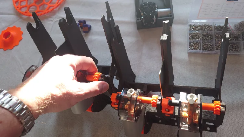
Front Modules
Install the feeders and feeder modules in the front modules, guide the cable in the middle and just slide the modules together but do not tighten the socket heads yet.
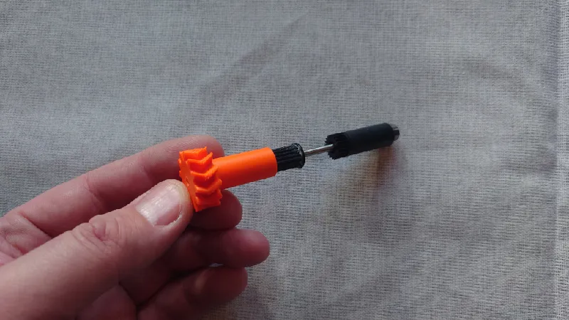
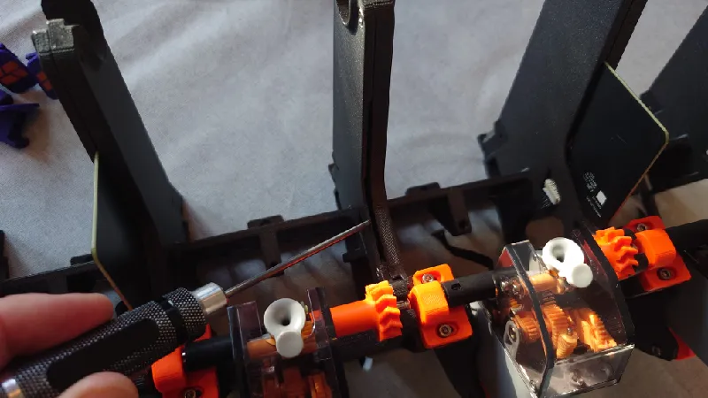
The front roller with the drive gear attaches using the drive gear holder and a replaceable threaded block as pictured.
For the heated inserts version it uses heated inserts here instead.
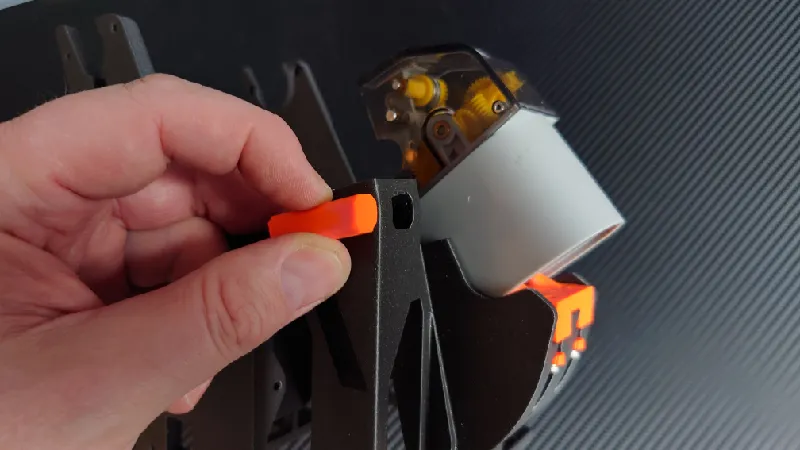
Just press in the feeder block in the cutout, take notice of the direction as it follows the curvature of the feeder (pic above).
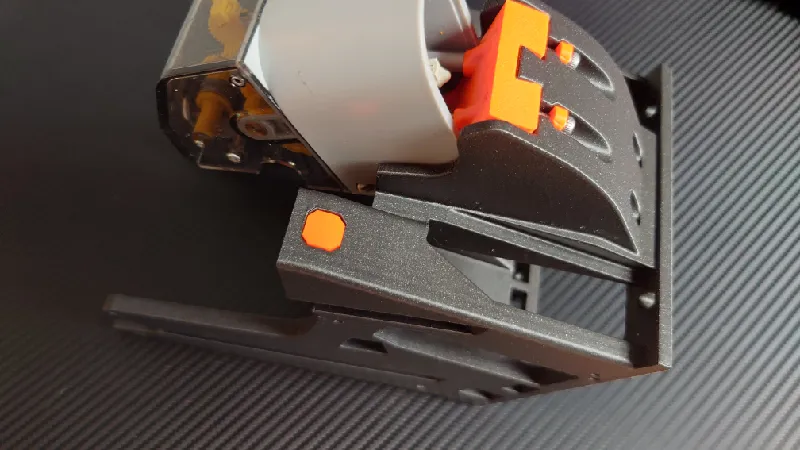
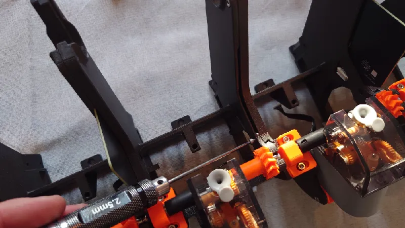
Install the adjustable drive gear holder using two M3-16 mm socket heads. Don't tighten yet.
Install the roller with the drive gear sleeve. Pictured here is in the open position so the gear can be removed or serviced, normally is should be tightened down so the roller spins with just a tiny bit of friction.
A good starting point is to have the right side of the drive gear holder lining up with the column below it.
Install the rest of the feeders and drive gears.
Then tighten the four socket heads from below:

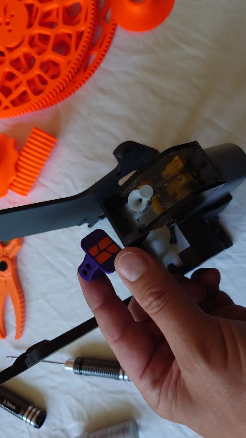
RFID Boards
Since version 1.02 of Python, RFID is fully supported in all four spool slots.
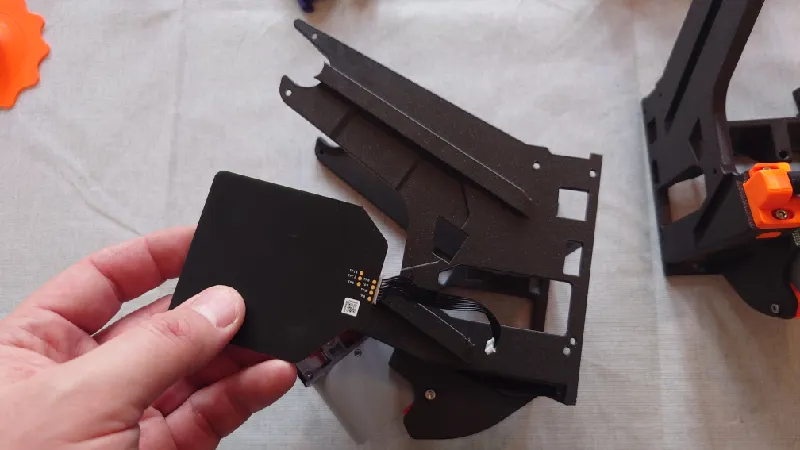
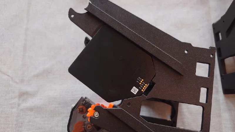
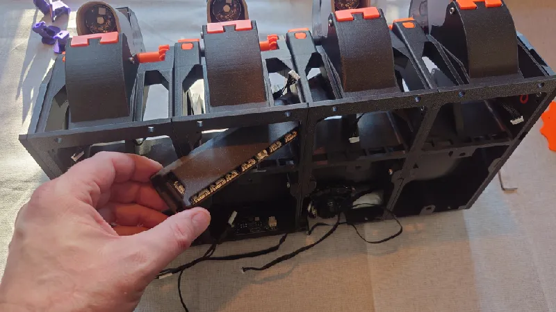
The RFID boards are placed in cutouts of front module one and three. Simply place the RFID board in the slot and guide the cable through then it sits secured with friction against the neighbouring front module.
It's important you place the RFID modules in slot one and three! Take notice of the RFID board direction below, the PCB plug should be on the other side as pictured with the cable in the cutout.
The front modules each come with dual large size dovetails, male and female on each side. These are the key parts for the structure and strength of the design.
The front modules by themselves aren't very strong but once paired they are. So be a little careful with this next step.
To install, simply align the dovetails and slide them together at the angled direction with the RFID board in the middle, as pictured:
Module one and two done, with the RFID board in the middle:
Do the same for module three and four:
Assembly the two module blocks the same way:
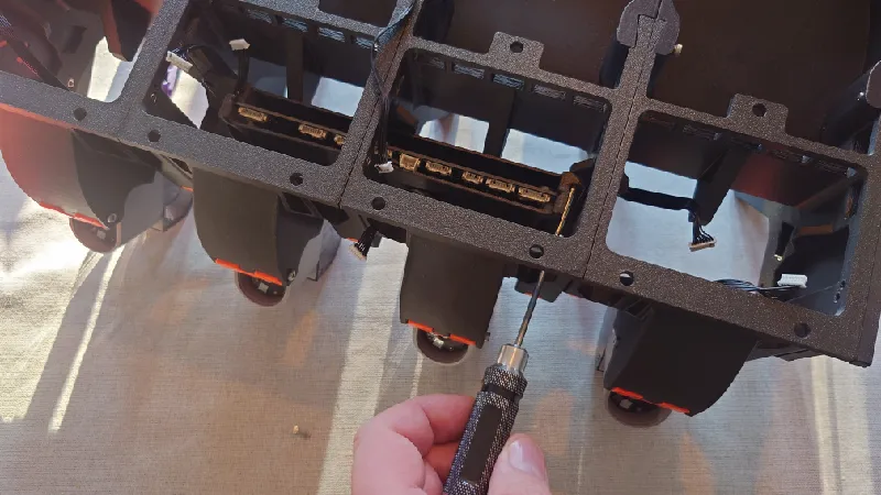
Time to screw the front modules together using 12 x M3-8 mm socket heads:
For each module, use four M3-8 mm screws, the first two are at the top of the spool holder columns.
The third screw sits in the middle near the edge of the RFID board cutout.
The fourth sits in the bottom so it's easiest if you flip the assembly over and tighten it.
Do the same for the other two modules. For some areas it's a good idea to use a short 2.5 mm hex key, for example when the RFID board is in the way.
Of course for the front modules will have some cutouts where there are no RFID boards, just ignore these.
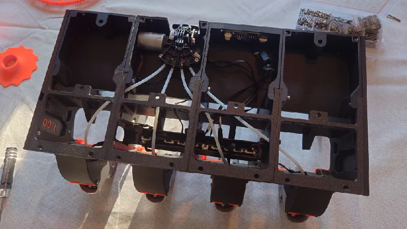
Rear Modules
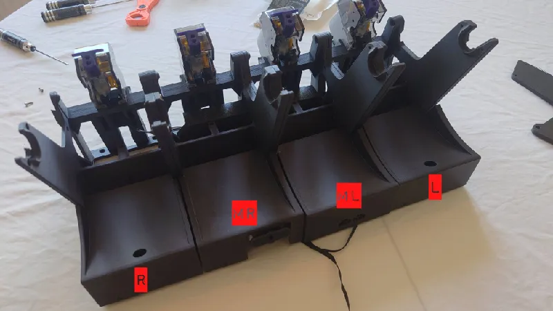
Place the four rear modules as below.
They're all marked in the printed parts:
L = Left
ML = Middle Left (PCB)
MR = Middle Right (Motor)
R = Right
So the L is placed to the rear left, looking at it from the front (notice: below is the rear view and and earlier version of Python but the rear modules are the same).
Use 6 x M3-25 mm socket heads to secure the front modules to the rear modules.
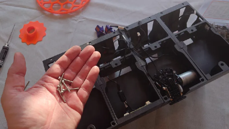
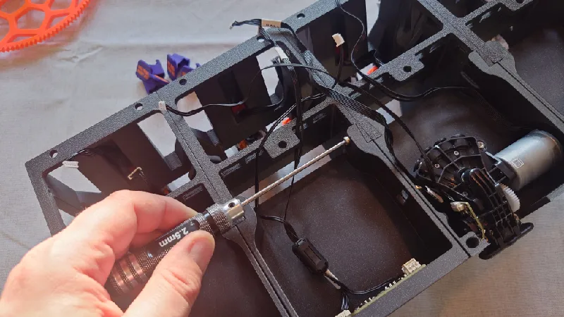
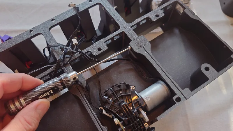
The bottom socket heads (closest to the roof) of the rear modules are difficult to reach so you can either just skip these or use a short hex key to tighten them. You don't really need to secure it if you don't want, I honestly skip them myself.
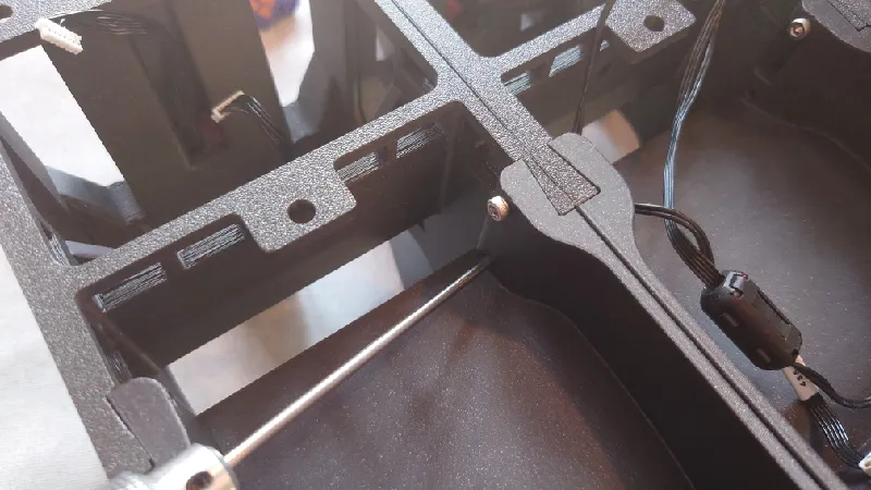
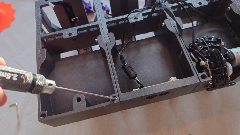
Next, use 3 x M3-25 mm socket heads to secure the rear of the rear modules together, they are angled at 40 degrees.
Left and Right Sides
These install using the same dovetail system as the front modules.
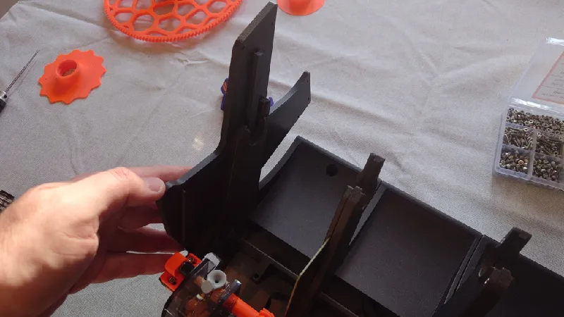
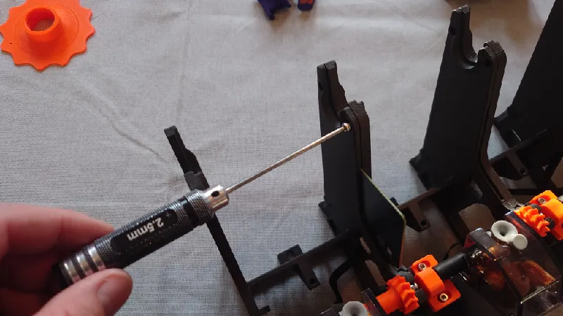
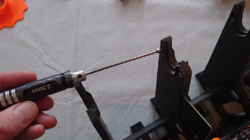
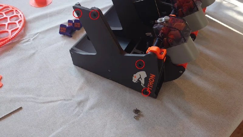
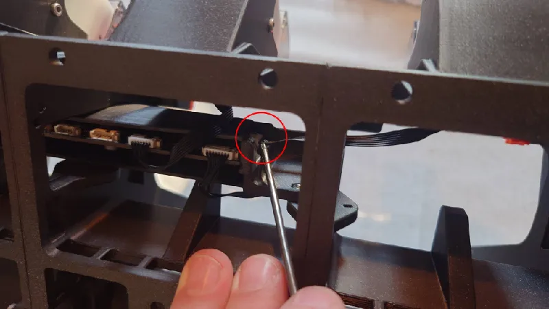
Slide in the left side and secure with three M3-16 mm screws in the red circled positions:
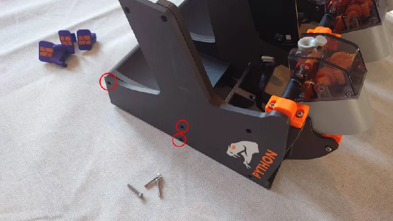
Continue with 4 x M3-8 mm socket heads in these locations:
Optionally, you can use one M3-12 mm here from the inside out but it's optional and not really needed.
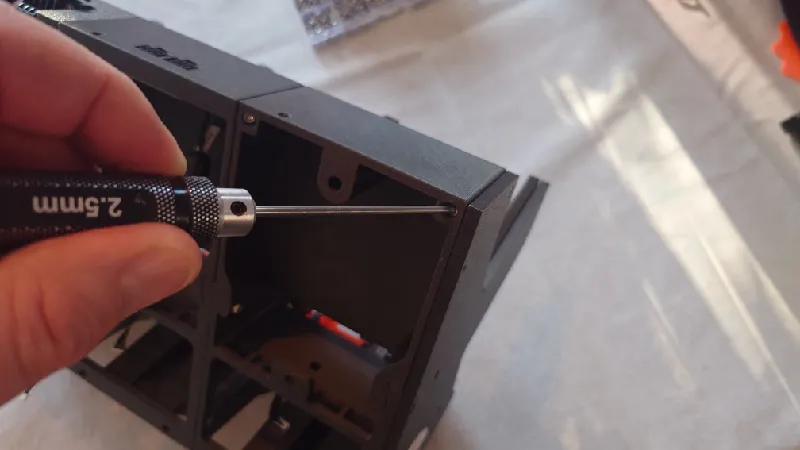
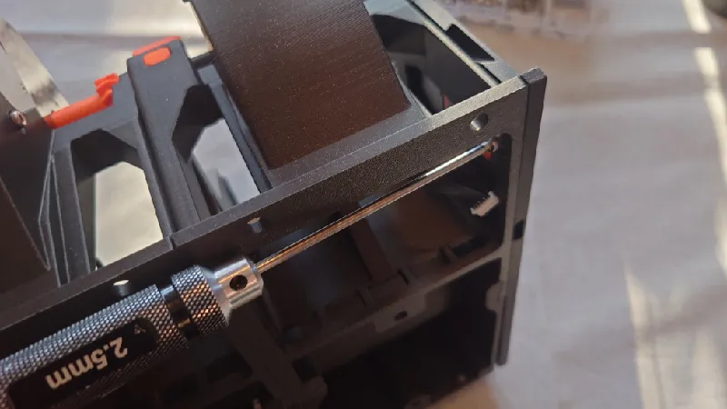
Slide in the right side and use four M3-8 mm to tighten it from the inside out. Two at the spool columns, one in the middle as pictured below and one at the bottom. Here it is useful with a short 2.5 mm hex key.
Finally, add one M3-16 mm from the outside in.
Also, fasten the right side with 2 x M3-16 mm from the inside out.
Slide in the Main PCB in its printed casing to the middle.
Secure it with two M3 screws (8 mm), one on each side.
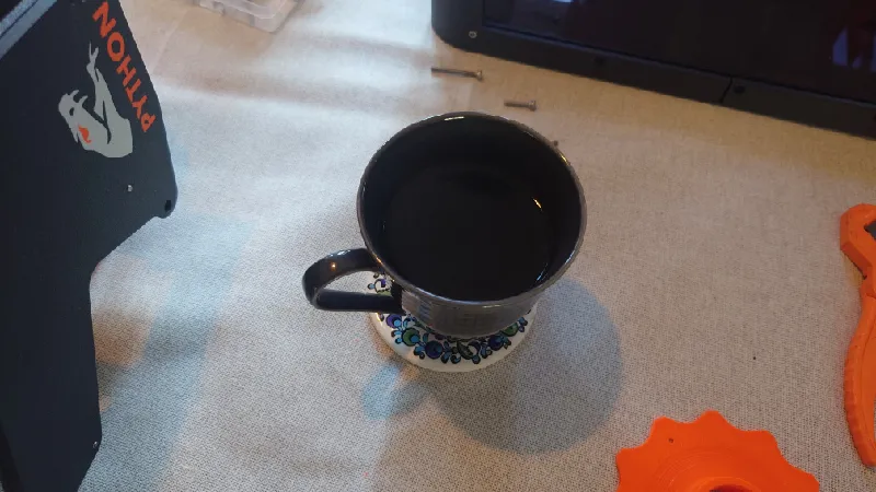
Now the main assembly is done. Time for a cup of industrial strength coffee.
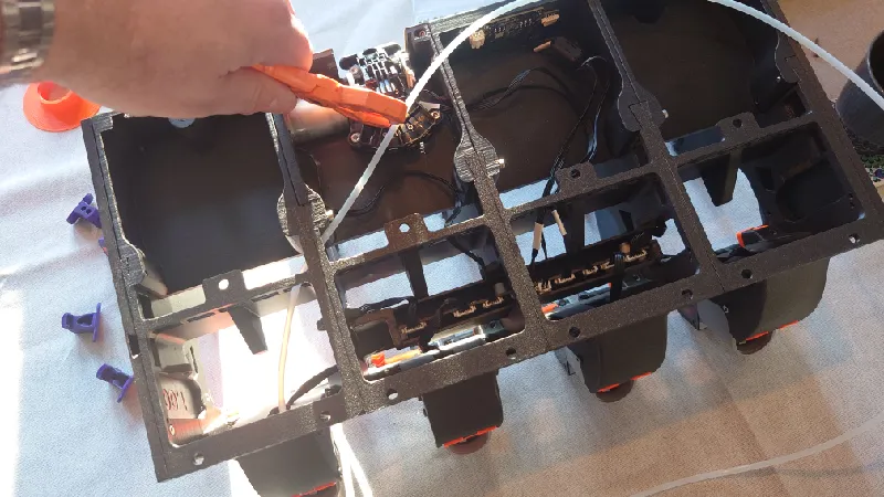
Connect the two RFID cables
The RFID cables reach but they are very short so you need to work out how to route them. My suggested routing is as below:
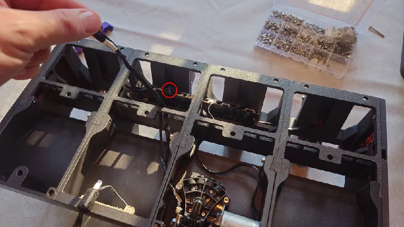
For the leftmost module (front module one), guide the cable in the large opening below then connect it.
Make sure you've not accidently unplugged the RFID cable from the board when installing so double check both of these.
For the right RFID, route it behind the PCB holder then under and up:
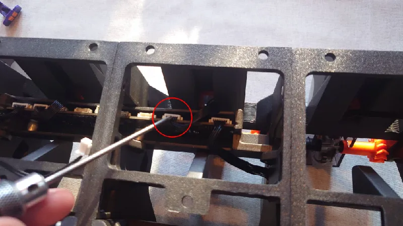
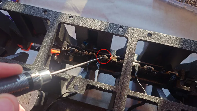
Connect the four feeder cables as pictured. The outer feeders are connected to the sides of the board and feeder two and three (middle) connect to the connectors as pictured below.
Feeder one:
Feeder two:
Feeder three:
Feeder four:
Connecting the rest of the cables
By now you should already have connected the four front feeder cables and the two RFID board cables. Let's do the rest.
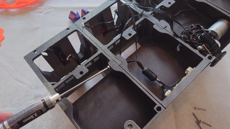
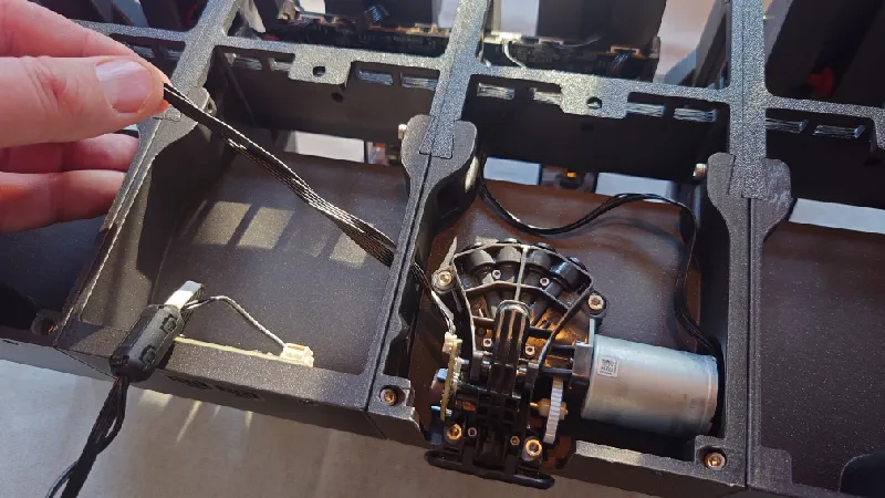
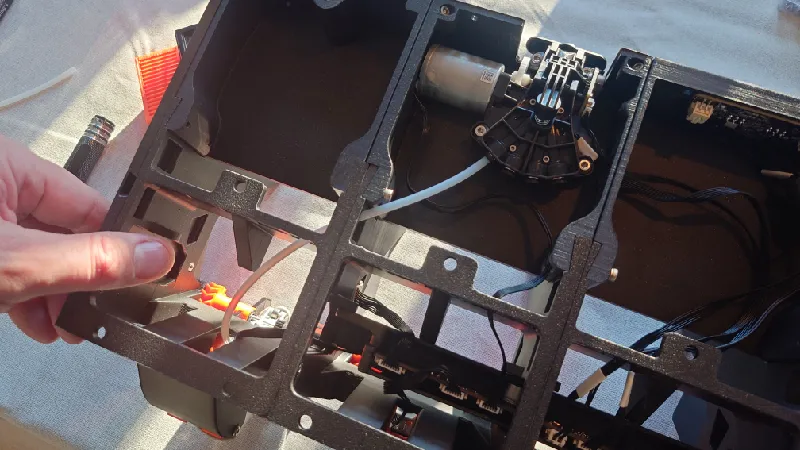
Start with the motor cable. Guide the cable through the holes, this is the suggested route.
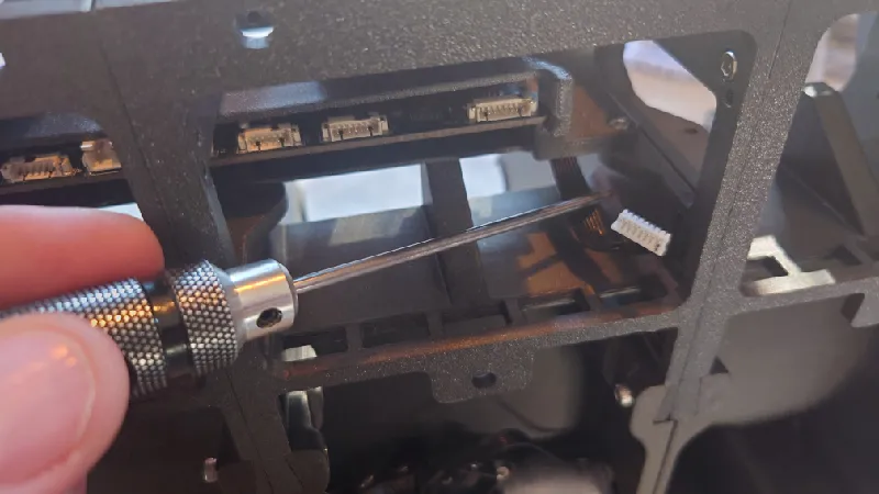
Then connect it here on the PCB, third plug from the right.
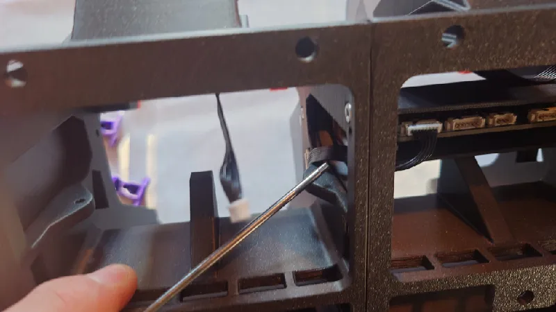
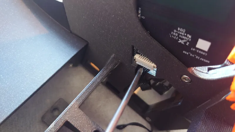
Next route the Hall sensor and Speed measurement cables from the internal AMS filament hub. First guide it through the holes on the left into the PCB module then through the front module.
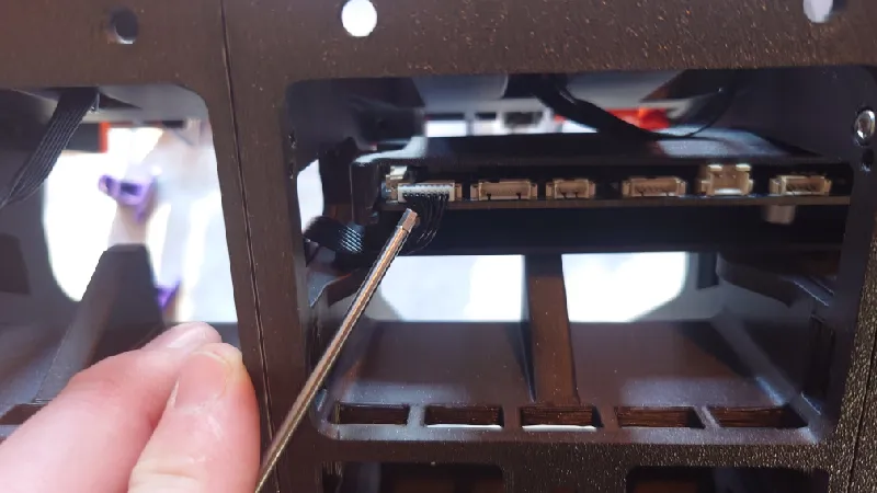
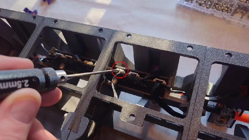
The Speed measurement cable goes here (circled), it's the third plug from the left:
While the Hall sensor cable goes here (fourth plug from the left):
Next, guide the cables from the small rear PCB through.
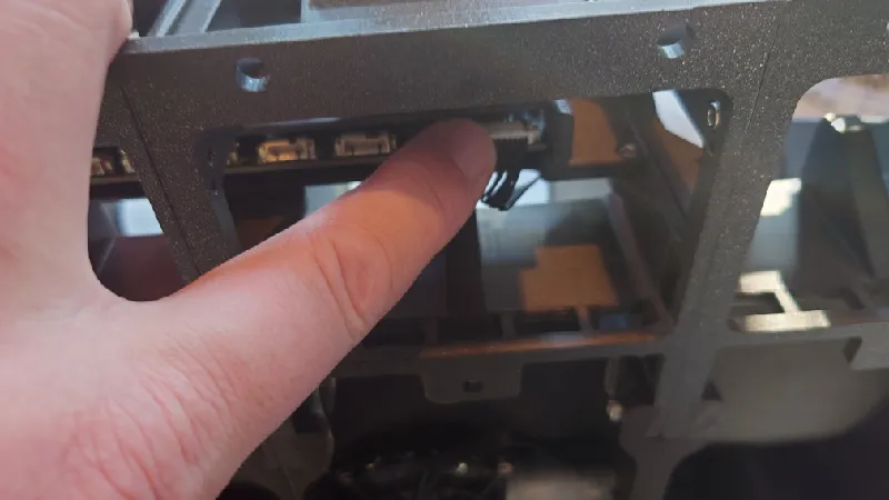
Connect the Power cable here, fifth plug from the left:
And the Bus cable here, sixth plug from the left:
Nearly there. Just the the PTFE tubes left to do.
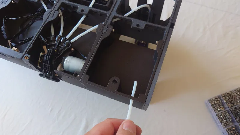
Cut PTFE Tubes
The stock PTFE tubes are too short so get a new set from Bambu Lab or from AliExpress.
Pull on it to ensure it's locked in place.
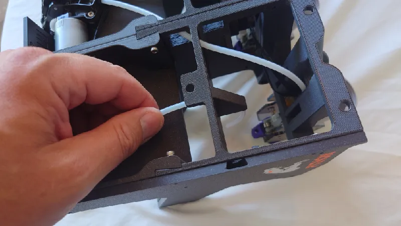
Guide through and cut the tube to length. Try to keep the bend radius at a minimum so don't have the tubes too long but not too short either. A good rule of thumb is cut it a few cm extra when it's stretched.
Do the rest of the tubes. There are multiple options for routing the tubes but these are the suggested routes to keep the tubes as straight as possible and to avoid any small radius bends, we want the bend radius as large as possible. Make sure the tubes are not too long.
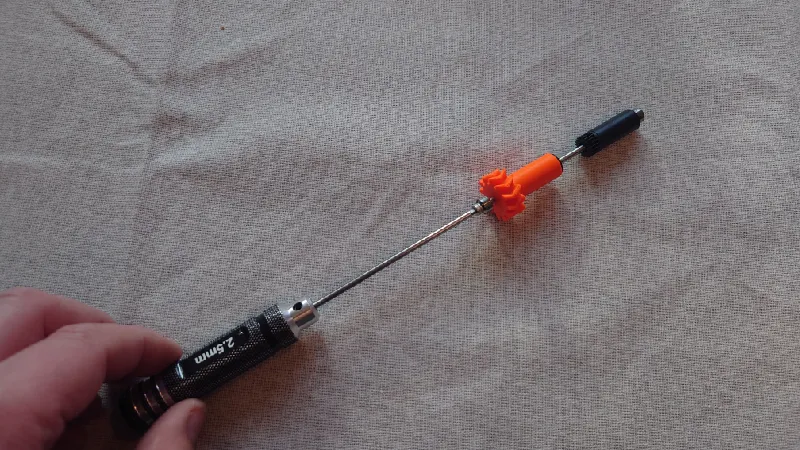
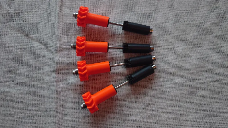
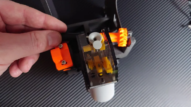
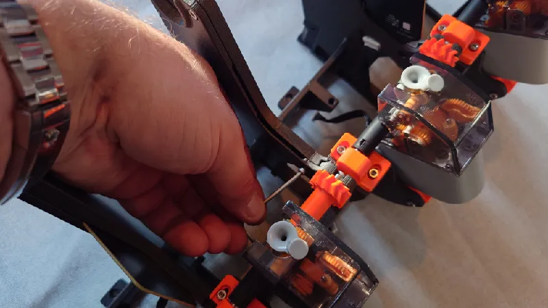
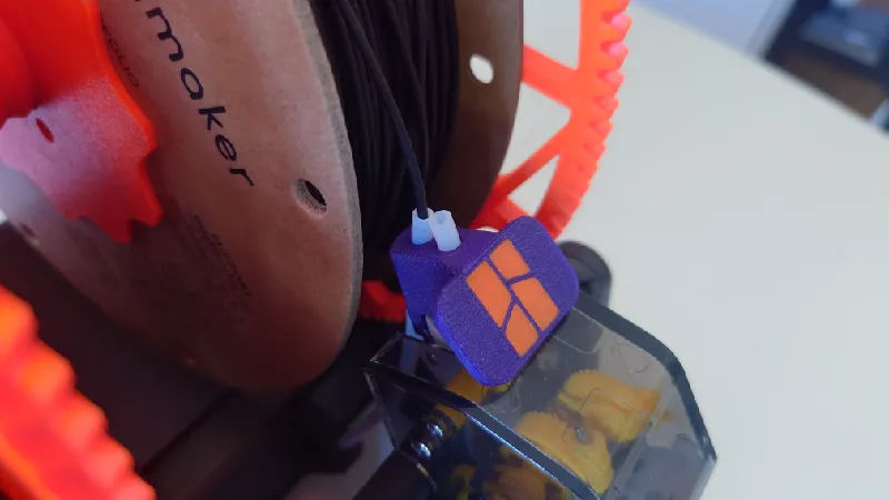
Optional PTFE Buttons
Now is a good idea to also install the optional PTFE buttons, they're especially useful for using the external spool function as it has dual PTFE channels, the front for normal AMS loading and the rear for the external spool function.
But its main benefit is of course the large flat load button that makes it much easier to load filaments and it also saves the feeder funnels from wear.
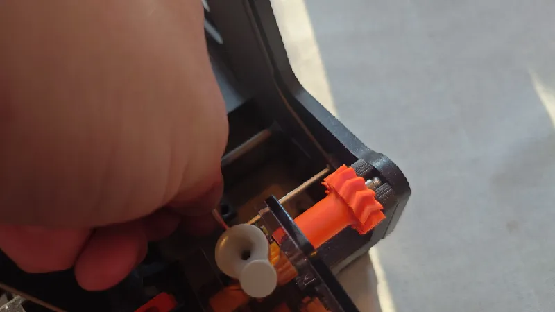
To install, press the feeder button front with a finger while sliding on the printed button. There is a short video below you can view as well.
External Spool Function - Connecting Tubes
The external spool function is a pretty cool feature of Python AMS. It allows for bypassing the AMS internals completely and using Python as an external spool holder.
It is useful for abrasive filaments for example such as CF or GF infused or Glow in the dark filaments or for printing TPU, none of which are suitable or in some cases not possible at all using the AMS.
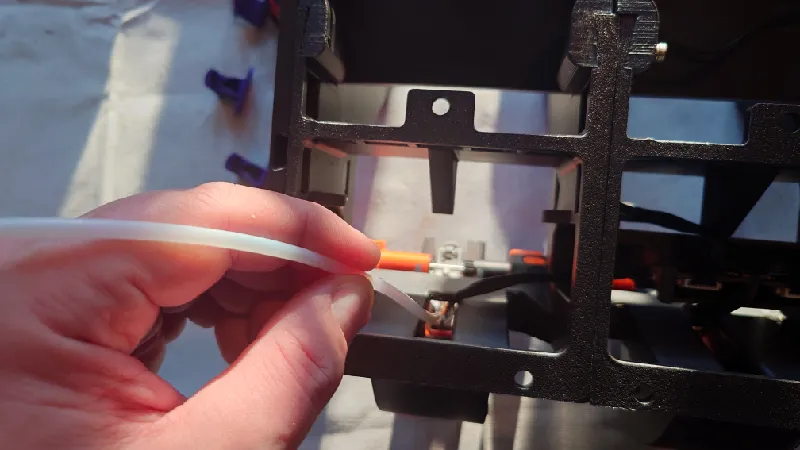
First, slide the tube through the hole in the rear cutout. Some pictures are from the previous version of Python but the function and routing is unchanged in 1.05.
For this function it's recommended to use the optional Python AMS - PTFE Load Buttons I mentioned above.
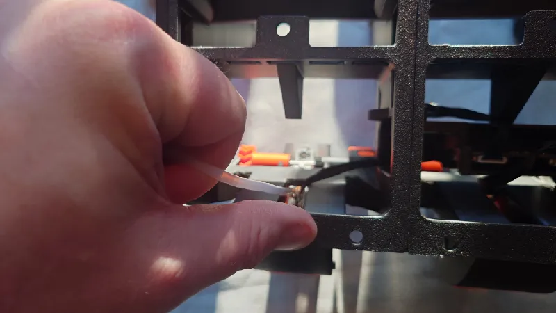
Next, guide it through the middle hole of the front module and have it stick up a bit.
Finally, slide it through the PTFE load button's rear hole. That way you can either use the AMS normally by loading it in the front hole or to bypass the AMS by using the rear hole.
If you use the external spool function, I suggest cutting the PTFE tubes fairly short so they don't interfere with eachother. The front hole is for normal AMS loading and the rear role is for the external spool function.
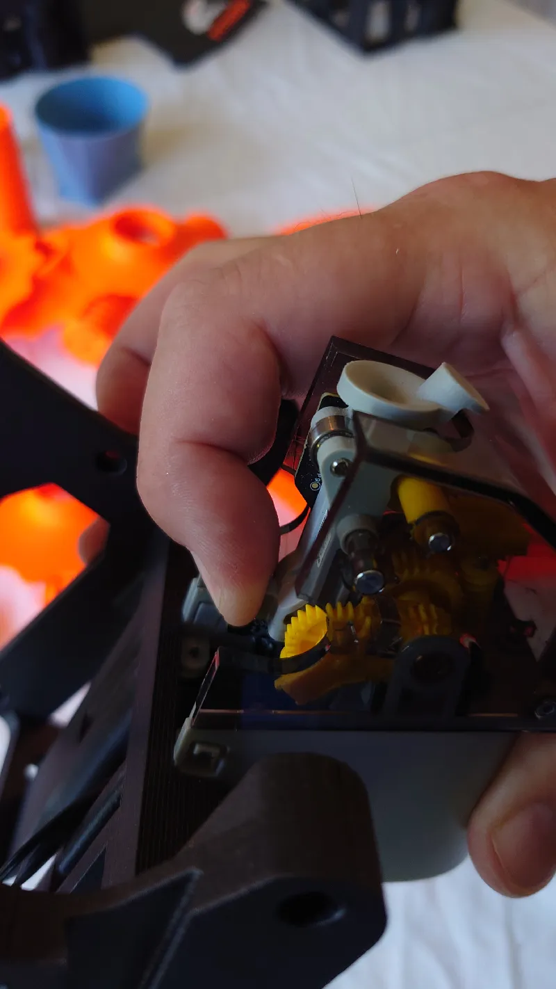
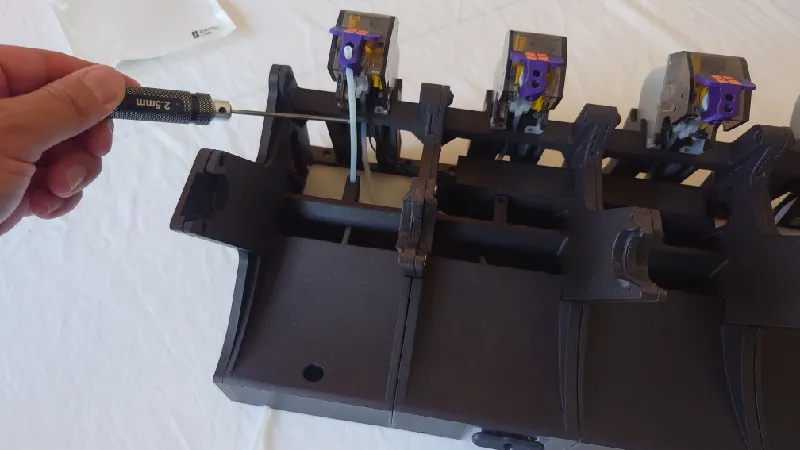
Adjusting The Feeder Modules
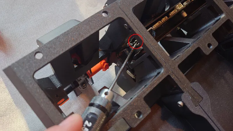
A good rule of thumb is to have the feeder as close to the roller as possible without the roller grabbing the yellow gear while you rotate the roller by hand. It should not grab in either rotation. See the area circled below.
Adjust it so it just grabs it then back off a fraction:


Assembly Complete - Some Final Things
All done!
- Make sure there is not too much tension on the rollers / drive gear sleeves, they should spin with very low rolling resistance. If not, adjust the drive gear holders. Too much friction can cause issues when the AMS is retracting the spool.
- Make sure you center and fully tighten the spool holders before printing. The spool holders do a pretty good job of auto centering the spools when tightening but it's a thing to keep in mind. You can also use the Adaptive Spool Holder that auto tightens the spools on the rods.
- When loading the spools, ensure you align the spool holder on top of the front roller sleeve. The roller sleeve is extra wide to allow for easy loading. But before you start a print, ensure the gears mesh and so it doesn't run outside it.
- For certain RFID spools you may need to use thicker “spool holder bottom” for spool slot two and four in order for it to get proper reading, with other words, bring the spool closer to the RFID board.
- Also when using small small spools, use a thicker spool holder bottom so it lines up with the middle of the feeder.
Renders

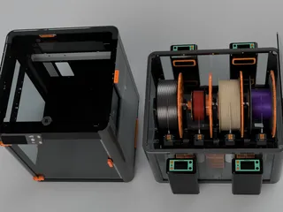
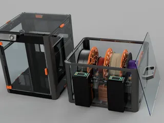
With Python Enclosure (No Heaters) and P1P with Vision Enclosure:
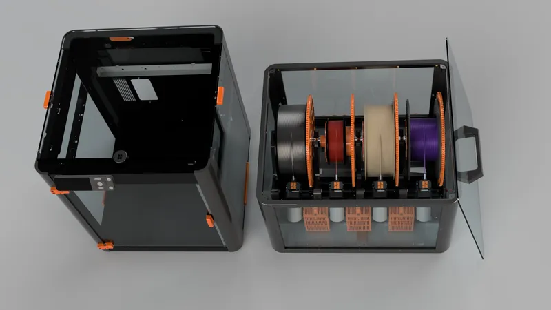
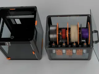
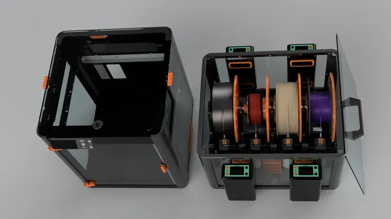
With Python Enclosure (Two Front Polymaker PolyDryers) and P1P with Vision Enclosure:
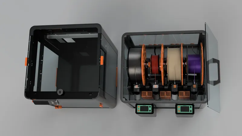
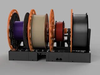
With Python Enclosure (Four Polymaker PolyDryers) and P1P with Vision Enclosure:
Tags
Model origin
The author marked this model as their own original creation.


