JL PIP pine Tree

Descripción
PDFMade in collaboration with: @cplum_2524920
Lesson Plan and Constraints:
We have been tasked to create a 3D-printed object where the inner layers would shake and extrude out making a 3D shape.
Summary / How to:
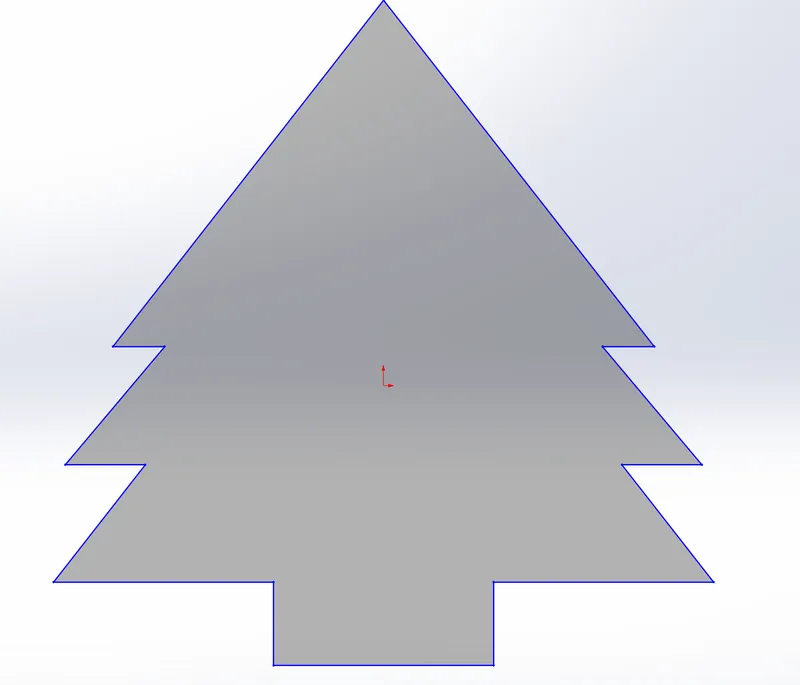
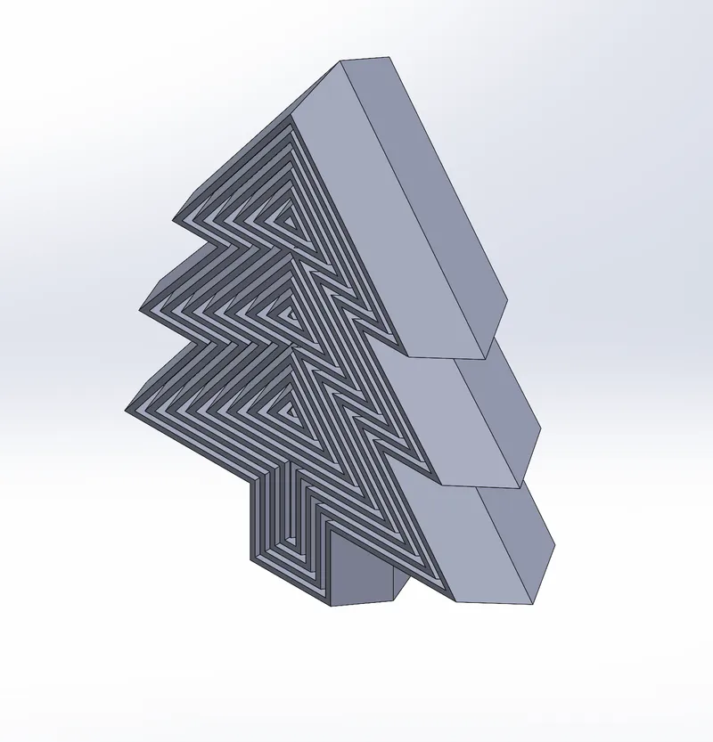
My Print In Place (PIP) design features a pine tree, with the tree being offset 11 times, resulting in 12 layers in total. I chose a pine tree because Christmas is just around the corner.
For anyone creating their own PIP pine tree, I recommend using the offset tool to create the inner layers.
Creating constraint box:
- Create a new part
- Select the front plane
- For this design, it does not work when it is inside a constraint box
- Draw a 1.35 cm line up the origin
- Then from the bottom of the line that was just drawn draw a 3.55 cm line across
(these lines will be the trunk of the tree and a reference for the rest of the tree)
Creating the branches/triangles:
- From the top of the first line we drew make another line that is 3.55 cm long.
- Following this make a diagonal line that goes to the right, make this line 1.90 cm long and an angle of 52°
- Repeat steps 1 and 2 but use the following measurements
(1.30 cm, 2.50 cm, 50°) (0.85 cm, 7.11 cm, 52°)
- Make a construction line that goes through the figure and mirror the half across the construction line so it fills in the shape
Your sketch should look like this :
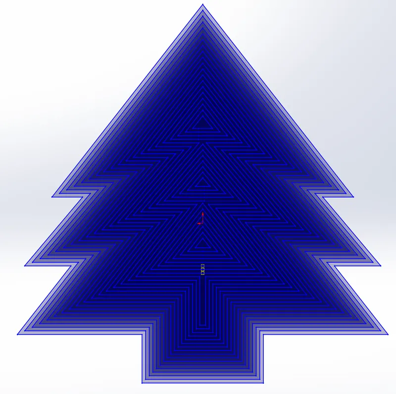
Offset entities:
- First, select the Offset entities tool in Solidworks
- Then select the sketch, you will notice a yellow outline that goes around the sketch
- In the Offset entities settings set the parameters to 0.1 cm
- Select the box that says reverse
- Check of the yellow lines are correct
- After you have verified that it looks correct click the green check mark to offset the sketch.
- You will continue to offset every new sketch that is drawn until you are unable to
Once finished it should look like this:
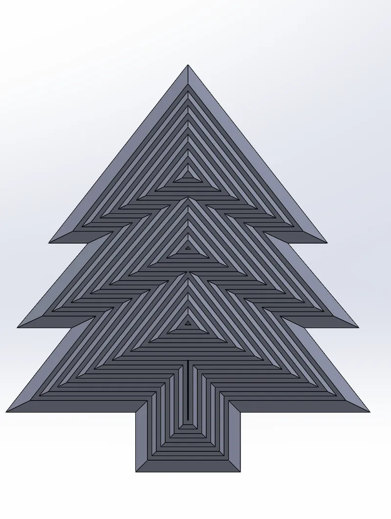
Boss-Extrude your sketch:
- Go out of sketch mode, when done the sketch should become gray. Make sure to select ONLY the outside line
- Go to the features tab and select Boss-Extrude
- Set the height to 1.00 cm
- And the degree to 15.00 degrees
- And press the green check mark
Extrude-Cut:
- Click the second-most outer layer of your sketch
- Click the button with the two arrows to reverse the direction of the cut
(make sure you are cutting into the shape)
- If one of the settings says {Blind} change it to [through-All]
- For the height of the cut set it to 1. oo cm
- Set the degree of the cut to 15.00 degrees
(Keep repeating these steps until you reach 10)
Once finished the first side should look like this:
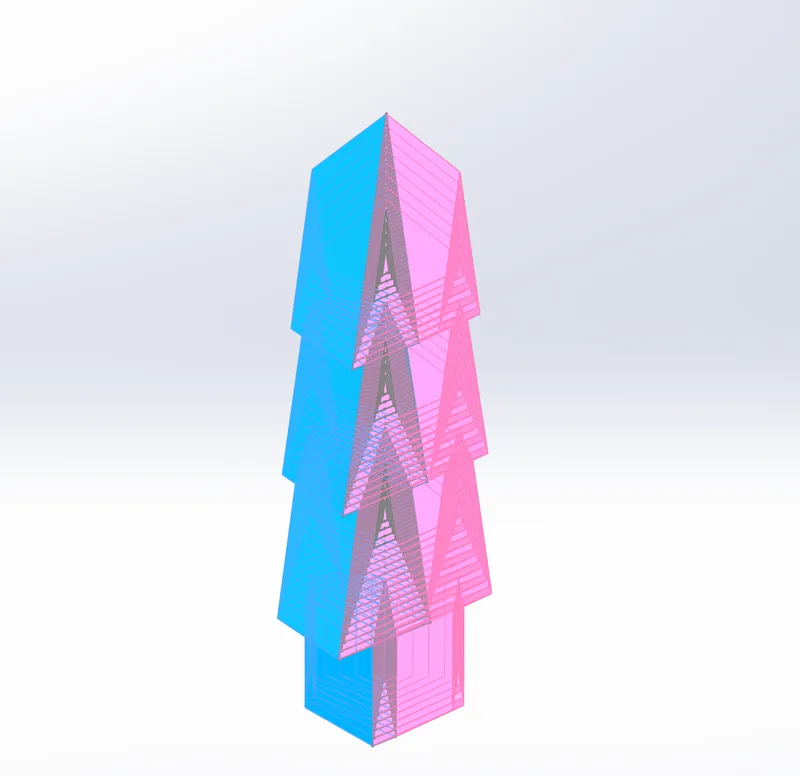
Mirror the figure:
- Select the front plane used for the feature tree (front plane)
- Navigate to the mirror settings, then change the menu option to [Bodies].
- Select every ring, and make sure [Merge solids] is selected
- Click the green check mark to finalize the mirror, after this is done the other half of the tree should be filled out
Your mirror should look like this:
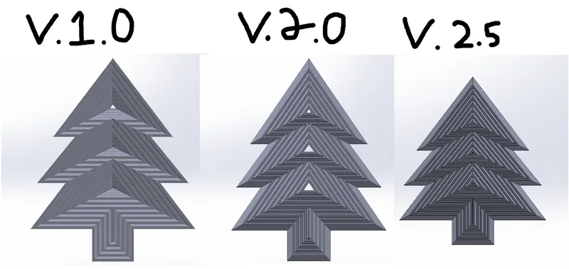
Design Choices / Changes:
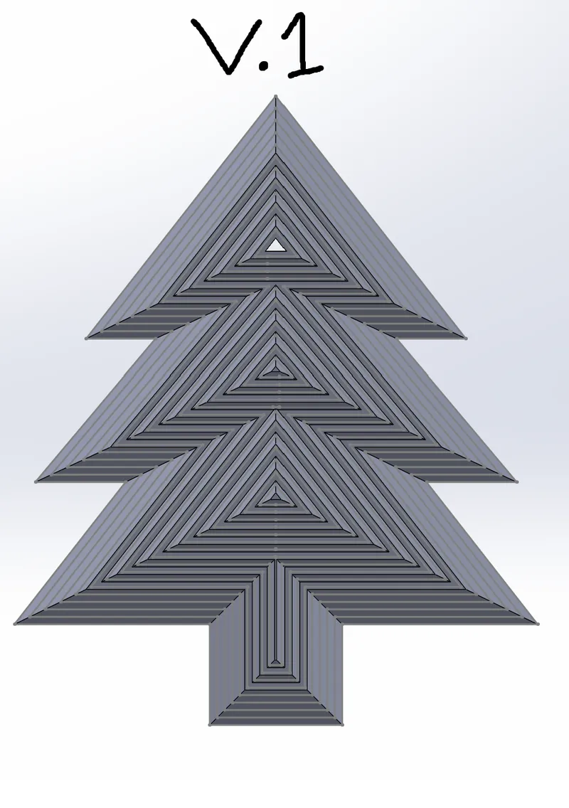
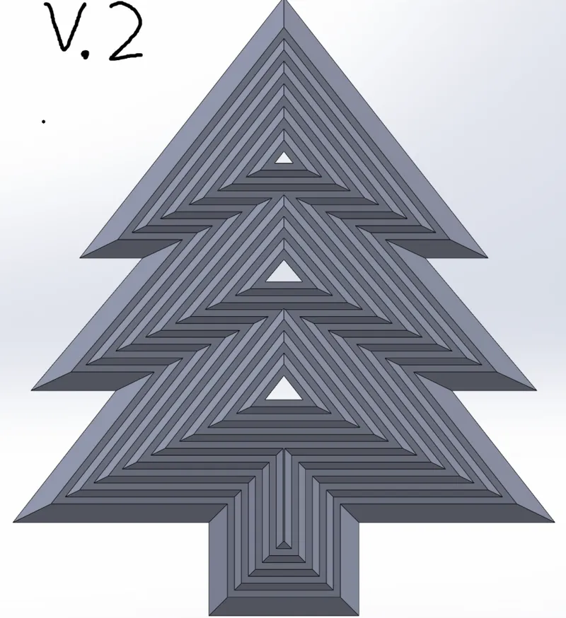
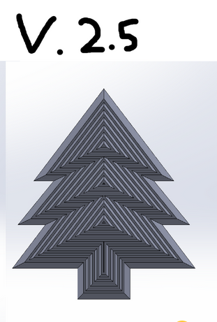
When designing pine tree V.1.0, we initially chose an offset angle of 25° for each layer. We liked these dimensions because they made the tree appear thicker. However, once we finalized the design, we found that we could only fit about 6 offsets within the entire sketch. After printing, we realized that if we stuck with the 25° offset, not only would we be limited to just 6 layers, but the side meant to be concave wouldn’t have enough space or depth to form correctly. This is why for pine tree PIP V.2.5 we changed the degree for the offsets to 15° so the tree would be flatter and have more room to add more offsets and alow it to secsefully go inside out.
TREE PIP V1.0
For the first design, we went with 25°. This caused the figure to not have enough offsets, which made the max number of layers to be 6. This design was simple and easy but did not work overall due to the layers occasionally getting stuck on each other and the triangles not going as deep as we wanted.
TREE PIP V2.0:
For our second version, we went with a lower degree for the offsets and cuts, we brought it from 25° to 15°. This small number change was a huge difference in our design. After this change, we were able to add up to 23 layers! It was a major improvement, the triangles would not get stuck on each other and the shapes would extrude farther
TREE PIP V2.5:
Although this was a success, 23 layers proved too much for the printers, so we had to reduce the design from 23 layers to 12. While it was a bit smaller, it would still work effectively and only be slightly shorter.
Origen del modelo
El autor ha marcado este modelo como su creación original.


