Weather Station using a ESP32

Description
PDFWeather Station using a ESP32
You will have to check the github for the project. I found everything I needed to create this circuit.
https://github.com/lmarzen/esp32-weather-epd
About the model
I created this model myself. You will not need to use support as I design for 3D print and to avoid support. The lid can be printed face up or down as the holes are designed to be printable up side down.
You will find two lids, one with an embossed logo of OpenWeather and one that appread to not have the logo, but in fact as it cut out using 0.01 mm. The slicer will ignore it, but you can colorize it and print with an AMS/MMS. If you do not want a logo use that one and do not colorize.
The BME280 has a special spot where there is a embedded intake and exhaust port on the back of the box so the sensor is more isolated from the condition inside the box.
What you will need to assemble this
The M2 and M3 screws I use have a very flat head, I know it's very specific, but this is how the model was made with.
Hardware that I use to build the station
- FireBeetle 2 ESP32-E Microcontroller
- Good Display 7.5in e-paper GDEY075T7
- Good Display DESPI-C02 Adapter Board
- PL 905090 battery
- BME280 5V module (the small one)
Hardware needed related to the model itself
- 8 x M3 threaded inserts (I use the long one) (M3x6x4.5) (Design hole size 4.4 mm)
- 5 x M2 threaded inserts (use short one) (M2x3x3.5) (Design hole size 3.3 mm)
- 4 x M3 screw (14 mm to 20 mm); for the screen
- 4 x M3 screw (6 mm et 14 mm); for the lid
- 5 x M2 screw (3 mm to 5 mm); for the retaining clip and BME280
- 4 x M1.4 self tapping screw (4 mm to 5 mm); for the FireBeetle
Assembly instructions
Install all the threaded inserts in the base.
Insert the screen in the frame, the ribbon cable goes through the slit in the frame and then insert the retaining bracket behind the screen. You will see at the top of the retaining bracket there are 3 tabs that align in the top of the frame to hold that part in place.
Install your circuit inside the base, make sure you have long enough cable. I used old IDE ribbon cable and crimped a connector for the two modules. Please note that it is impossible to install a header on the FireBeetle, you will have to solder the wires directly to the FireBeetle.
Edits
I added an untested screen frame that has 0.6 mm bigger opening, I got a comment that said that the screen was a little tight in their print. I added two new files untested. I will remove the untested notation when I get a comment that is was printed and is working for someone, for now the two screen frame and screen frame retainer with the notation (0.6 mm bigger clearance) should be considered experimental.
Some image of the design details
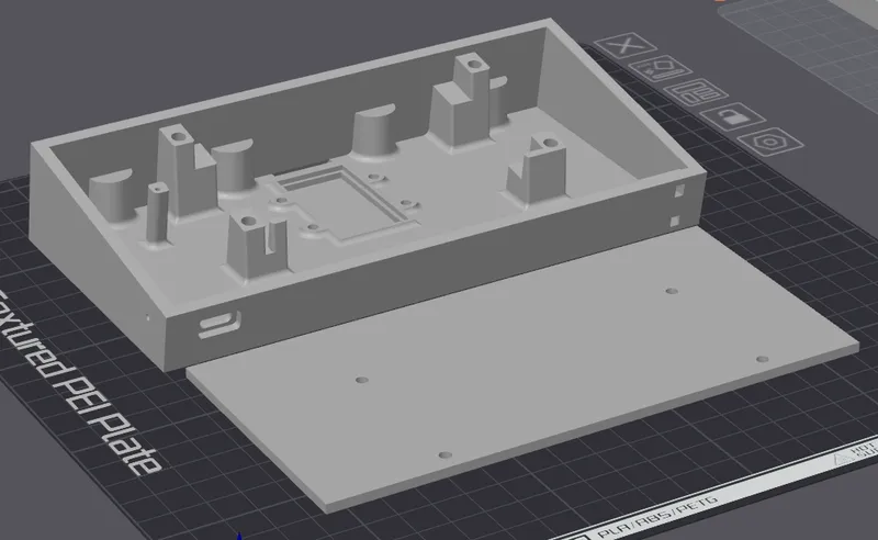
BME280 location
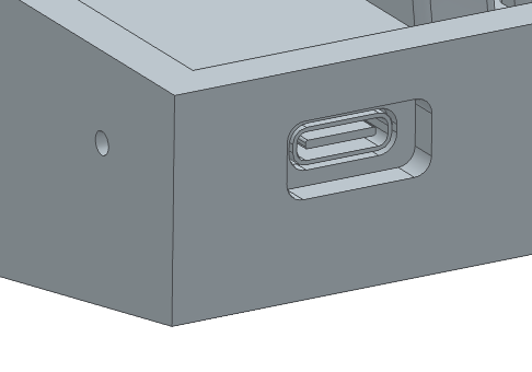
FireBeetle USB-C and Reset pin hole
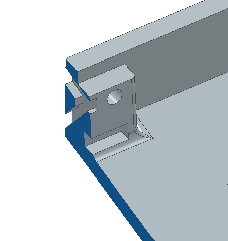
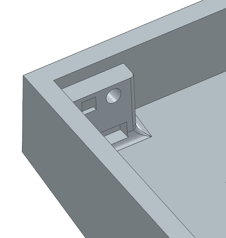
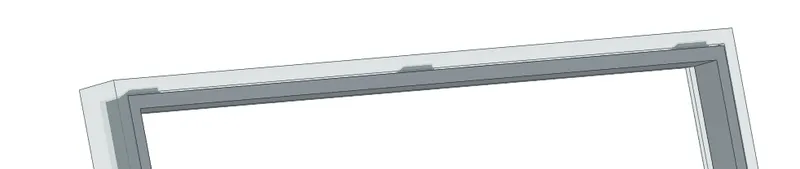
Hooks in the top of the Screen Back Retaining
Printing details
I printed it with Overture ROCK PLA Rock White. At 0.2 mm layer height and a 0.4 mm nozzle on a BambuLab P1S. There is nothing special about the print parameters, just a normal easy print.
Here is my build plate one when I'm not making a multi color lid. Note that the lid is facing with the logo facing down. Remember the holes have been design to be printable this way.
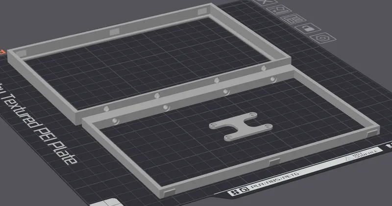
Second build plate, you can clearly see the tabs on the top of the Screen Back Retaining. Again everything is printed easily without supports.
Model origin
The author marked this model as their own original creation.