LGX Lite + CAN bus + PCB Fan for Stealthburner

Description
PDFIf you have an original version of the strain relief, check out the reliability update at the end of the description. It is a quick and easy fix.
When this project started, I wanted a CAN bus conversion for my Voron 2.4R2 but did not see any mods that used an LGX Lite extruder. Since the expansion board was not much larger than my previous hartk-based toolhead board, I mounted it to the side of the toolhead. This has the benefit of keeping wires from potentially interfering with the rear drag chain, an issue I saw with some early mods. However, a side-mount also means that I need a small X endstop spacer for clearance. The strain relief is extremely sturdy, and the wire cover gives everything a nice, clean aesthetic. I choose the EBB42 CAN bus expansion board after seeing several people struggle with the size of the connectors on the EBB36 board.
Supplies & Preparation
For my project you will need:
- Voron 2.4R2 with deleted X and Y cable chains
- Stealthburner toolhead
- BigTreeTech EBB42 CAN bus expansion board
- Bondtech LGX Lite extruder
- Microswitch X endstop mounted to X carriage; or sensorless X axis homing
I chose to model mounts for a 4010 fan since I had room on my toolhead. It cools the whole CAN bus expansion board and part of the extruder stepper motor, though I was primarily concerned about the TMC2209 stepper driver. The full hardware list assumes supplies for mounting the fan, but you can choose to skip this part of the project.
This project uses the following fasteners: (2) M3x10 FHCS; (2) M3x8 SHCS; (8) M3x12 SHCS; (2) M3x20 SHCS; (2) M3x30 SHCS; (2) M3x8 BHCS; (3) M3x20 BHCS; (11) M3x5x4 Heat Set Inserts; (2) M3x24 threaded spacer. There are labels for specific parts in the picture gallery. As an alternative to the 24 mm long spacers, you can use (2) M3x20 threaded spacers with 3 mm thick washers from the EBB42 accessories bag.
Parts & Assembly
Please note that this is not a comprehensive CAN bus conversion guide for a Voron. This project is a repository of custom mounts and commentary on their assembly.
1. You need to disassemble the LGX Lite extruder to make some modifications. Undo the two screws holding the body pieces together. Insert square nuts (from the original included accessories) into all four of the bottom slots in addition to the two slots on the right side. If you want to, now is the time to rotate the motor and shift where the wires route across the toolhead. Reassemble the extruder body with two M3x30 SHCS. The longer screws allow for the threaded spacer to attach to the back of the stepper motor.
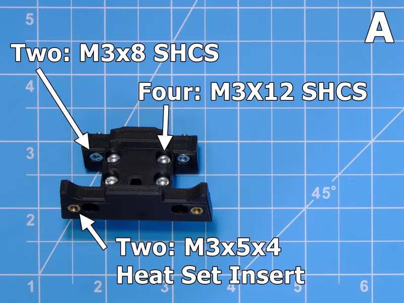
2. Figure A. Attach the extruder to the mount with M3x12 SHCS. Do not mount this assembly to the X carriage yet. It will be easier to complete more steps first. Note the two heat set inserts.
3. Figures B, C. You will need 5 heat set inserts for these spacers. They mount to the extruder with M3x10 flat head cap screws. Even though it is camouflaged in the picture, do not forget the printed spacer! It ensures that the extruder gears are spaced from the components on the back of the pcb.
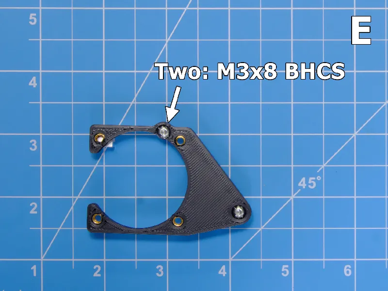
4. Figures D, E. The fan mount uses four heat set inserts, and attaches to the standoffs behind the stepper motor with M3x8 BHCS. Socket head screws will interfere with the fan. Use button head! Mounting the fan (with M3x12 SHCS for a GDStime 4010) will make the mount much more rigid. The open side of the fan mount functions as a passthrough for the fan wires.
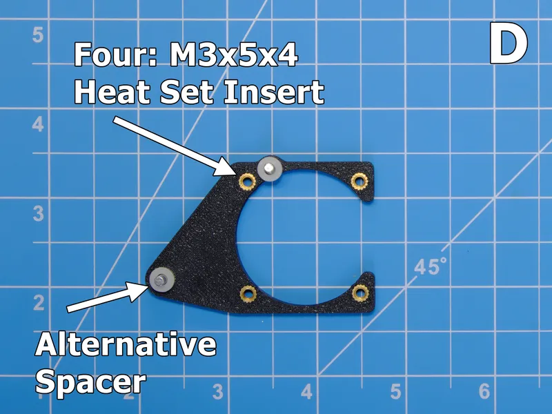
Alternative hardware: I had M3x20 threaded spacers leftover from my previous LGX Lite mount and cable chain anchor. In order to get enough clearance, I added 3 mm of spacers (like the spacers included in the EBB42 accessory bag) and used longer screws to secure the fan mount.
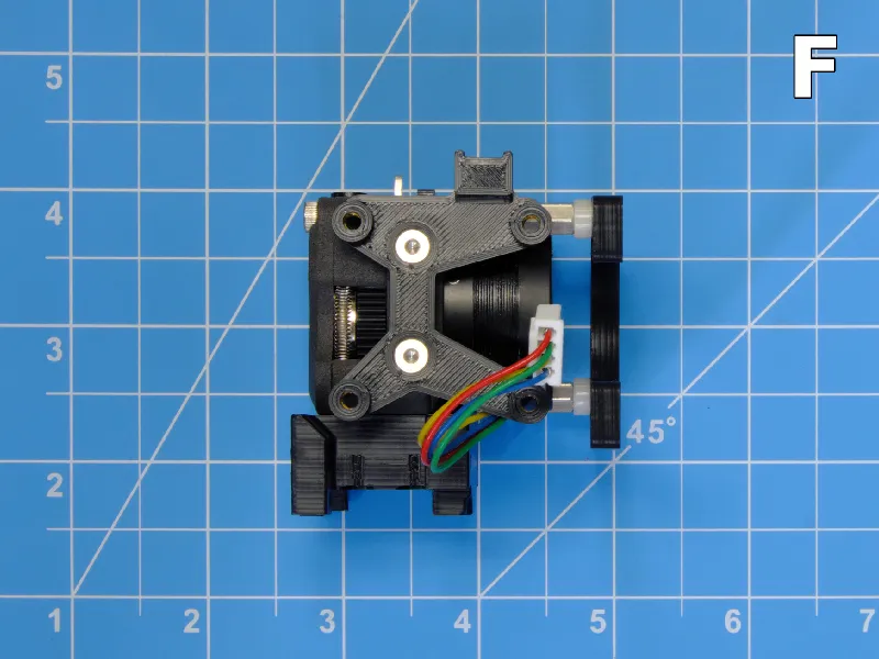
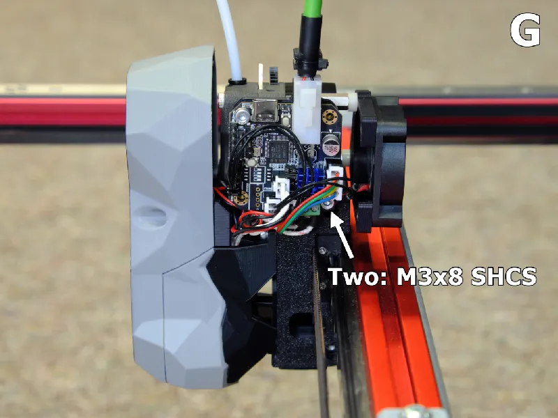
5. Figures F, G. You are ready to mount the extruder and attach the expansion board. Use M3x8 SHCS in the upper left and lower right corners. With the toolhead components in place, you can now prepare your wiring and connectors. Note that the heater wires can potentially interfere with the bottom of the toolhead cover. I did not have enough clearance to use the plastic strain relief on the bootlace crimp on my heater wires. I ended up cutting the plastic protector off and using heat shrink instead.
Note that when you mount the Stealthburner fan shroud in place, you can exchange the two M3x25 SHCS for two shorter M3x20 SHCS. While the original screws have a purpose, they can potentially protrude into space where you might run wires. I found that the shorter screws helped with wiring.
6. Once you have the wiring finished, you can put on the cover with two M3x20 BHCS. The umbilical strain relief attaches with one M3x20 BHCS and has a groove for a ziptie. There are several downloads for the strain relief for varying umbilical diameters.
Note: I wired my pcb cooling fan into the heater fan plug since I did not have any extra fan ports. This runs the pcb fan anytime the toolhead might be extruding. Be sure that your fans stay under the power limit for all fan ports combined (1 amp for my version).
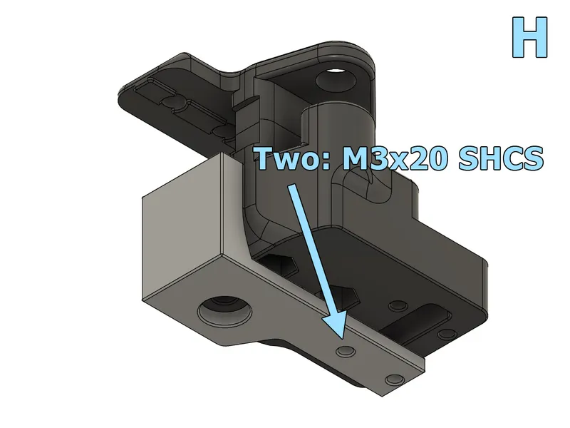
7. Figure H. The toolhead cover will need a few extra millimeters of clearance at the front right idler for the Z belts. You will need to add an endstop spacer on the right XY joint with two M3x20 SHCS.
X Endstop & Endstop Spacer
Installing the endstop spacer will change the homing behavior on your printer! Walk through the relevant startup checks on the Voron docs: https://docs.vorondesign.com/build/startup/#xy-homing-check.
In my CAN bus conversion, I went from an XY endstop pod from an LDO kit to an Omron D2F-5L microswitch mounted on the X carriage. I started with a large spacer (present in the pictures) but later found that a 3 mm spacer had sufficient clearance. I did lose 2 mm of travel, and I needed to adjust all X positions referenced in my config files. I use klicky and auto_z_calibration mods so this meant checking:
- printer.cfg: [stepper_x] position_endstop, position_max
- klicky-macros.cfg: [gcode_macro _Probe_Variables] variable_z_endstop_x
- klicky-variables.cfg: [gcode_macro _User_Variables]
variable_max_bed_x, variable_z_endstop_x, variable_docklocation_x - auto_z.cfg: [z_calibration] nozzle_xy_position, switch_xy_position
- other custom mods and macros that use travel locations
I have included several endstop spacer sizes for download. Even though the 3 mm spacer should work, I would recommend printing out and keeping a large spacer on hand just in case
A note for Voron Trident: I am not sure what kind of spacer is required for a Trident. I believe that the lead screws should have better clearance than the Z belts. However, I am not confident in stating the cover has adequate clearance until I can install the parts on a Trident and see for myself. Please share your experience if you try these mods on a Trident.
Thank You
I used the following guides while doing my own CAN bus conversion, and perhaps you will find them useful:
- https://github.com/bigtreetech/EBB
- https://github.com/maz0r/klipper_canbus/blob/main/index.md
- https://github.com/EricZimmerman/VoronTools/blob/main/EBB_CAN.md
- https://canbus.esoterical.online/
Thanks to all the people who worked on CAN bus mods before me! Thanks for visiting, and enjoy!
Minor updates: I switched this project to a remix since I did use Voron CAD files to make the extruder mount. The other models are my own design. The license has been updated to GPL 3 to match the license for Voron files.
Minor update: I edited the extruder mount to eliminate extremely thin walls near the four mounting screws. It will not alter the functionality of the part, but it should look a little nicer after printing.
Reliability update!
I have remodeled the strain relief to be taller and recommend printing a new one if you have the old version. It now attaches with an M3x20 BHCS instead of a 16 mm screw. This should help the ziptie have a firm grip on the outer jacket of the umbilical cable and keep it away fom the more delicate stranded wires. (My ziptie migrated down onto the stranded wires and eventually caused a failing connection after a few hundred hours of prints.). The added height should also make attaching the crimp connectors a little easier.
Minor update: Esoterical guide has moved from github to a dedicated webpage. I also added pictures to the text description to improve the instructions.
Tags
Model origin
The author remixed this model.
Differences of the remix compared to the original
When designing CAN Bus mounts for Stealthburner, I started with the Clockwork 2 main body and motor plate to design the extruder mount. The other models used in this assembly are my own design.