NanoGuard Bank Vault

Description
PDFFeatures
- Functional vault door - moving gears and locking pins
- Convenient size - reduces print time and filament usage, largest part fits within 120 mm x 120 mm x 80 mm print volume
- Smooth motion - parts with tight, standard, and loose tolerance
- No supports - designed for easy 3D printing.
Start with a Test Print
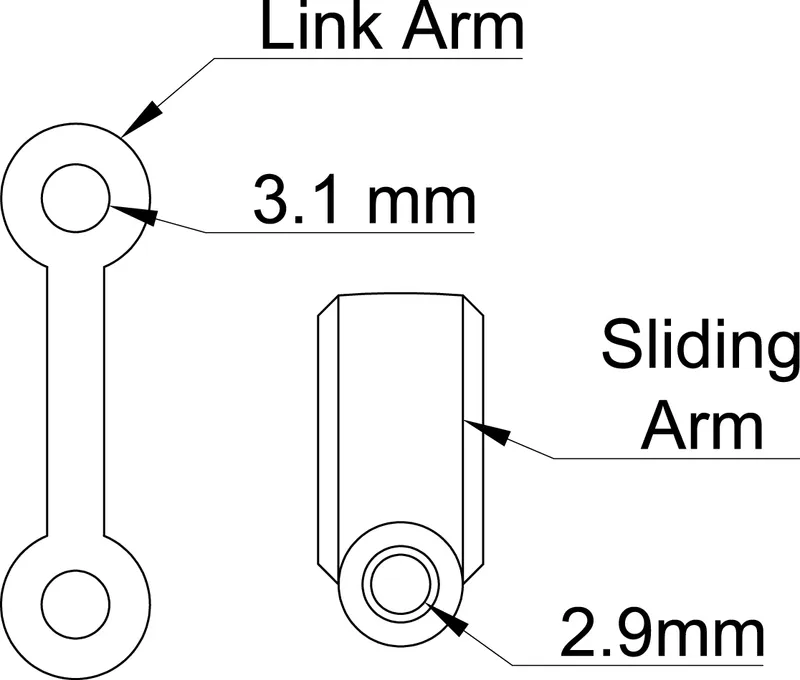
Because there are many moving parts I recommend making the test print first. Test fit the pieces and choose parts that are smooth without being excessively loose.
Put an M3 screw through the holes on the link arm. The printed part should swing freely without friction. If the hole is too tight you can drill out the hole. (If you do not have a 3 or 3.1 mm drill bit, a 1/8 inch drill bit is 3.18 mm.) An M3 screw should thread into the hole of the sliding arm without being loose.
Supplies
At the start of this project I made the decision to use screws for axles. This makes the joints smooth and robust, but introduces required hardware.
- (16) M3x6 screws
- or (8) M3x6 screws for the outer ring, and (8) M3x8 screws for the inner ring
- (2) M3x20 screws
- (3) M3x16 screws
- (2) M3 square nuts
- Glue (2-part epoxy, superglue, …)
Some lubrication is recommended (but not required) where the gears contact the gear housing.
Assembly
Follow along the pictures for a detailed step-by-step assembly guide. I labeled the location and size for screws, as well as areas that need glue and lubrication.
When installing screws for the arms, be sure to use sufficient downward pressure while rotating to get the threads started. Protip: Insert a slide arm into the faceplate first and then try installing a screw.
Thanks for visiting, and enjoy!
Tags
Model origin
The author marked this model as their own original creation.