Parametric ironing calibration test matrix

Description
PDFThe ironing process (and its results) depend of three variables: flow rate (FR), spacing between ironing passes (SBIP) and printing speed (PS).
The matrix shape allows to check two setting combinations at once; whilst we have three dimensions at our disposal, we need a flat surface to check the ironing, so two is the most that can be tested at once. The stepping shape, as long as the column and row steps (increments) are not the same, allow for recovery from a bad combination of settings and not carrying it out to another test surface. Modifiers for Slicer are used to insert the appropiate settings where needed; these can be "surface-only" (if you want to check only top surfaces) or "full", from buildplate to top surface, should you want to calibrate the as-of-yet-experimental option of "iron all solid surfaces" (which also irons in-model layers, not only top ones).
This model includes the option to add a recycling symbol, and for that it uses the Recymbol library. Whilst the OpenSCAD will work fine without it (it will just throw some errors), the library is extremely easy to install, and I use it so often, that is strongly recommended to. To install the library:
1) Download from the Recymbol page at Printables the "library.scad" file
2) Create a folder named "Recymbol" in your OpenSCAD library folder. (Go to OpenSCAD menu File->Show library folder if you need to check which is it.)
3) Move the file library.scad to that Recymbol folder. That's it, it's installed. No restart, registering, renothing required.
The symbol can be printed with the print-on-print technique, to use two or more colors in the same layer without an MMU unit. Just print the symbol, remove brim and purge lines, and print the matrix on top of it. Print-on-print requires a bit of offset in the "negative" part, already considered for in the customizer if you choose that option; but you can choose also to make the symbol in simple bridging and stacked bridging (which improves definition, but takes longer to render).
How to use it
(In the files, you'll find a PDF tutorial with a more detailed explanation; this here is just a shorter, no-pics version.)
You need to create an object with several variations of the two settings that you want to check; IMHO, is best to start with flow rate (FR) and spacing between ironing passes (SBIP) and, once you've these pinpointed, fine-tune the printing speed (PS).
To create your object, enter all the settings you want in the customizer window in OpenSCAD, press F6 for the render, then F7 or the "STL" button in top toolbar to export. The console will output a suggested filename that includes the parameters of the model, so you can recognize easily which is which.
After you've created your first object, then create all the modifiers for all the cells (combination of column and row). Load the matrix file into the slicer, apply all the modifiers to it (tip: you can load them all at once) and adjust the settings for each one of the modifiers. Another tip: the modifier objects are different only if the number of rows, columns, row step, column step or block size change; but they remain the same for either SBIP, FR, PS and their values, so you can create "masters" and save time just by replacing objects and changing some settings. Final tip: you can do two matrix objects, one with numbers on top surfaces (all text), one with only references on the side (side text only). Use the "all text" as a reference for the modifier settings, then replace it with the "side text only" version to get a completely flat block surface.
The modifiers are self-centering, meaning that if by some reason they result misaligned from the model, just set them at X0, Y0 and "drop to bed" (button at the right of Z coordinate) to make them fall in position.
You can use the provided .3mf files as a reference or base to make your own, but WARNING: these are intended for a 0.6 nozzle, the one I've set and I can test. Ironing is heavily dependant on nozzle size and geometry; an E3D 0.6 nozzle, for instance, not only has the hole a 50% greater than a 0.4 one, but also the flat part around the hole is a 50% greater in diameter. Likely, my best results with a 0.6 nozzle are at around 50% more the default settings (a 25% FR and 0.15 SBIP work well, if not best, for many of the materials tested with my 0.6; again, YMMV as my setup is non-standard).
What to look for
How to evaluate the printed object?
First of all, you should check the most blatant, obvious characteristics: blobs, lack of lines (or even almost a full layer); obvious roughness to the touch; the "reverse elephant foot", when material is dragged to the sides and ends up protruding (that means too much flow) and so on with all effects that may appear. Also, when using non-matte filaments, shinier is better, while more matte or satin results are worse (too hot). An effect that is not necessarily bad, but yet is meaningful, is the "bloating" or "visual bumpyness", especially of the shiny surface reflex, that seems to follow the infill pattern (more visible in clearly-patterned infills like gyroid, honeycomb, etc.). This might (or might not!) mean either, usually, too narrow a spacing that has to be wider, or too hot a nozzle which can be compensated by greater flow; but this bloating is not a "bad" result per se, and you can add more top layers to avoid this effect, if the best settings you've found do display this artifact.
Ironing is a "Goldilocks process": neither too hot nor too cold, neither too fast nor too slow... Blobs and "reverse elephant foot" (excess material on top, that likely will curl) are indicators of too many material (too slow, too little spacing, too much flow). Missing lines and layer failure are indicators of the opposite (likely a clogging caused by heat creep that could be solved with a greater flow rate or possibly a faster speed), so you'll need to either increment the flow rate, or adjust the spacing or the speed. Of course, if you change the spacing you will possibly need to adjust the flow (to avoid too sparse an infill), so it's great to check several combinations at once, isn't it?
When two or more different sets of settings work well, it's better to go for the one that's "more": greater flow, more spacing, faster speed. These are less likely to result in serious problems in long ironing passes. (Blobs tend to get on the sides, and are easier to remove and fix, than missing material.)
For the finest tuning, it will come in handy a loupe, USB microscope or magnifying glass. You don't need any of the fanciest stuff; a cheap USB scope or a no-name "forfeit currency detector magnifier" from AliExpress will do the trick; maybe even your phone camera, if it can focus from that near. You want to see ironing lines that are clearly defined and tightly-packed, but non-overlapping.
If you have two different sets of settings that look equally good, it’s better to settle for the one with the greater spacing, which also will have the greater flow. This will print faster and will reduce the danger of heat creep (not only because it prints less lines, but also because there is more material cooling the nozzle).
Final note
IMHO, ironing is the last thing you should calibrate in your printer+filament, meaning that you should have everything else well-tuned before starting this calibration process. There are lots of great calibration models in the wild, and let me suggest that you might also be interested in my collection of parametric calibration models. All of them can be suited to your needs and include a recycling symbol with the Recymbol library, as this one:
- The extruder multiplier/flow/walls calibration cube
- The simple temperature tower, with G-Code generator
- The advanced temperature tower, with G-Code generator and tests for bridges and overhangs
- The parametric overhang test, with support enforcer generator.
- The E-Cor tower (waveform for the TMC stepper drivers), with G-Code generator.
And, also, the non-parametric-but-modifiable precise Live-Z calibration test.
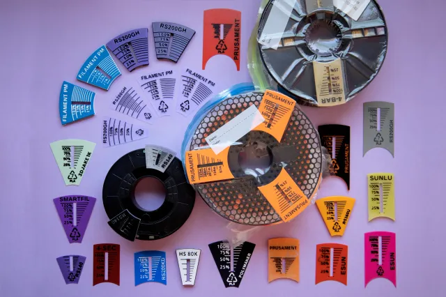
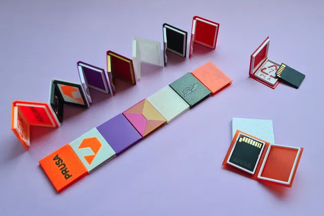
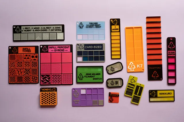
Once you're done testing and calibrating, sample your filaments with the parametric swatches!
Happy printing!
Tags
Model origin
The author remixed this model.