Mega Python AMS - Ultimate Bambu Lab AMS

Description
PDFUpdate March 10, 2025
A tiny update to the “two part” 28T and 29T gears. A couple of users have experienced issues that the outer dimensions were a little to large when using this combination, causing the gears to bind or twist a little which in turn caused too much friction for the spool rotation.
It makes sense as the flow ratio really needs to be spot on and there can be no snags in the printed parts else the gear when assembled can increase just a little bit in dimension compared to the solid option gear and therefore bind, the gear teeth are small and the tolerances are fairly low for smooth operation of the gears.
Therefore I have scaled these two gears a bit in the actual design. The updated files are now version 1.01b.
If you have experienced this you can just print the new parts:
- front-gear-29t-hard-1.01b.3mf
- front-gear-29t-tpu-1.01b.3mf
- rear-gear-28t-hard-1.01b.3mf
- rear-gear-28t-tpu-1.01b.3mf
If you prefer you can print the solid gears in TPU instead if you like but if you do use hard TPU such as 98A:
- front-gear-29t-solid-1.01.3mf
- rear-gear-28t-solid-1.01.3mf
The solid gear dimensions have not been scaled in design.
Update February 11, 2025
If you're looking for the 5 Kg version, it is available here.
Mega Python has been updated to version 1.01. It now uses the same feeder mounting as the regular Python and the gears and drive gear sleeves have been improved.
Changes:
- Front module and feeder module: Feeder adjustment is now fully adjustable, no set distance from the front module. The feeder modules are now attached from below for easier swapping and adjusting.
- Drive gear sleeve: Small adjustment for better gear meshing.
- 28T and 29T gears, wider gears with better meshing and less risk of the spool gear running off track.
- Feeder module washer: New printed part.
For those using version 1.00 and want the latest and greatest, there is an upgrade pack you can print so you don't have to reprint everything as many printed parts have not changed since version 1.00 and all versions are indeed cross compatible.
The upgrade pack is named mega-python-1.01-upgrade.zip.
If you don't want to do the full upgrade you can upgrade just the gears and drive gear sleeves for a smoother experience.
Buy Mega Python AMS
- Coming soon
Mega Python AMS has a strict non-commercial license, it can only be sold with licensing through Hume Beam Engineering Solutions.
Discord Support
Please do not send me direct messages here or ask questions in the comments, I have notifications turned off as I get so many requests here and elsewhere. Instead, please join our Discord server for suggestions and technical support. Thanks!
If you need any help with the build or want to leave feedback you can join us on Discord:
Our server is named “(Unofficial) QIDI Tech 3D Printers” so don't get confused when you join as it was initially setup for that brand of printers but we've expanded it to other brands and 3D printing in general as well as channels for some of my mods, it's where I generally hang out.
Welcome!
Troubleshooting
Gear meshing / retraction
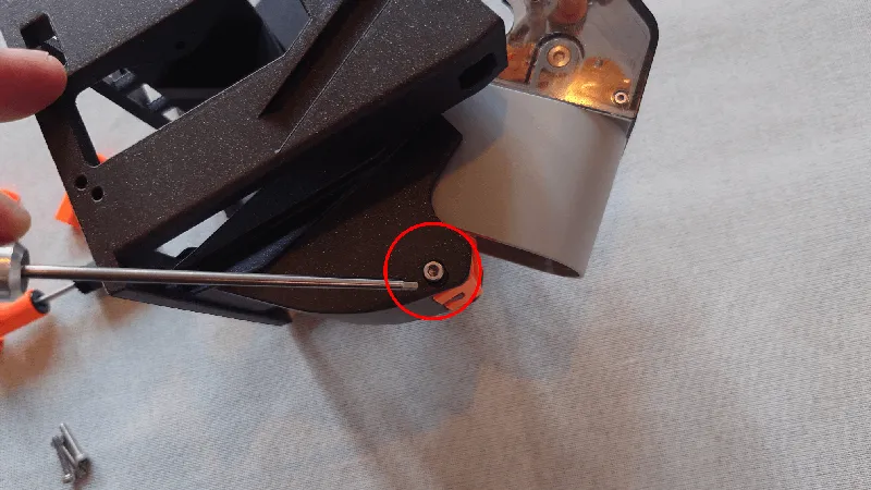
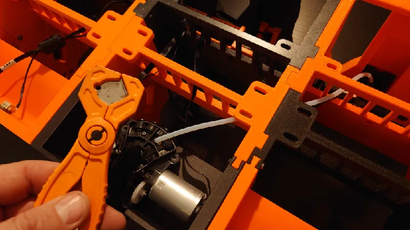
Almost all issues reported are related to the feeder position, it's important to get this right. For most people it's just set and forget but for some the position needs to be either closer to the front roller / drive gear and for some it needs to be further away.
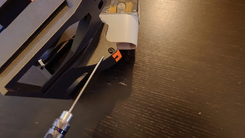
That said, a good rule of thumb is to have the feeder as close to the roller as possible without the roller grabbing the yellow gear while you rotate the roller by hand. It should not grab in either rotation. See the area circled below.
The pictures below are from the standard Python but the feeder modules and adjustments are identical.
Adjust it so it just grabs it then back off a fraction:

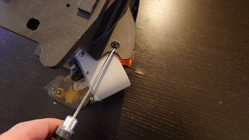
For version 1.01 the feeder modules are fastened with four screws from below.

For version 1.00 the modules attach from the sides.
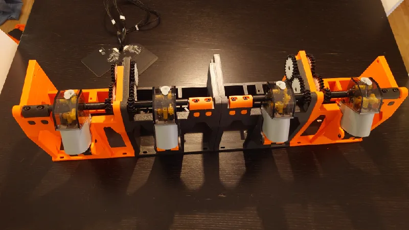
Intro
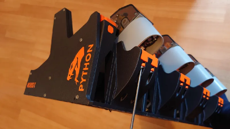
Mega Python is the big brother of Python AMS, a highly reliable and fully modular AMS system for the Bambu Lab X1/P1 series. It can be used with two to 16 spool slots, daisy chaining AMS units is possible, just like stock AMS. The sections are joined with dovetail joints and M3 socket heads. It has a built in wall mount and the spool holders are tilted back so it can just as easily be installed on a wall.
The Mega Python wall mount is compatible with the Honeycomb Storage Wall.
It supports spools up to 3 Kg with a maximum diameter of 310 mm and width of 120 mm, useful for print farms and for others who like to use larger spools. It's a bit more advanced as it uses more gears and bearings and involves extending the feeder cables but more on that later.
It also supports smaller spools of course, even tiny 250 g sample spools, same as normal Python.
Upgrading from Python AMS
For those wanting to “upgrade” from the standard sized Python AMS, these printed parts are identical so you don't have to reprint them:
- feeder-module-print-4pcs-1.01.3mf
- m3-wafer-head-gear-side-print-4pcs-1.01.3mf
- m3-wafer-head-top-side-print-4pcs-1.01.3mf
- spool-gear-135t-print-4pcs-1.01.3mf
- spool-holder-bottom-print-4pcs-1.01.3mf
- spool-holder-top-print-4pcs-1.01.3mf
The version numbers do not match, however, the parts are the same.
FAQ and Technical Specs
“Does this work like an AMS?”
- Absolutely, it works just like the stock AMS except the spools are sitting in spool holders, driven by double helical gears rather than on top of rollers. This highly increases the reliability and versatility.
“Can I use multiple Mega Python AMS?”
- Absolutely, you can daisy chain up to four of them for a 16 spool AMS.
“Can I hot plug an AMS to a printer?”
- Normally this works fine but to be sure please shut down your printer before plugging in Mega Python AMS (or a stock AMS for that matter!), it is much safer for the electronics. It avoids electricity spikes that can potentially happen if there is a poor connection between the AMS bus cable (black cable from printer to AMS) and the AMS power board, which in turn can damage the AMS main board.
- Hot-plugging can actually damage the electronics (AMS main board) so plug everything in before you boot up the printer.
“Do I need a stock AMS?”
- Yes. You use those parts and transfer over to Mega Python. All of the parts can be bought individually but it might be cheaper to just get an AMS rather than sourcing the parts individually, I haven't compared the prices.
“How large is Mega Python AMS?”
- Mega Python is huge. However, it is modular so you can use for example two or three modules only to slim it down. But for a full four spool setup the dimensions are: 644 mm (width) x 320mm (depth) x 322 mm (height) including spool holders and front feeders (full install).
- Using large 3 Kg spools it is even taller and deeper, with the maximum allowed spool diameter (310 mm) the space requirements are 644 (w) mm x 420 (d) mm x 365 (h) mm.
- Each module adds or subtracts 161 mm from the width as it is modular.
“Can I place Mega Python AMS on top of the printer?”
- It is quite large and heavy, especially with large spools so I recommend placing it next to the printer or wall mounting it.
“Do I need to use an enclosure?”
- It depends on which material you print, how long your prints are and the humidity of where you live. It doesn't have to be a fancy enclosure, you could just stick it in a large airtight container and drill holes for the PTFE tubes and cables, it works just as well.
- There is no offical Mega Python enclosure yet but it might come depending on how requested it is.
“Does it support RFID tags?”
- Mega Python fully supports the Bambu Lab spool RFID tags in all four spool slots.
“One feeder does not engage / disengage the front roller.”
- This is almost always due to a misalignment of the feeder.
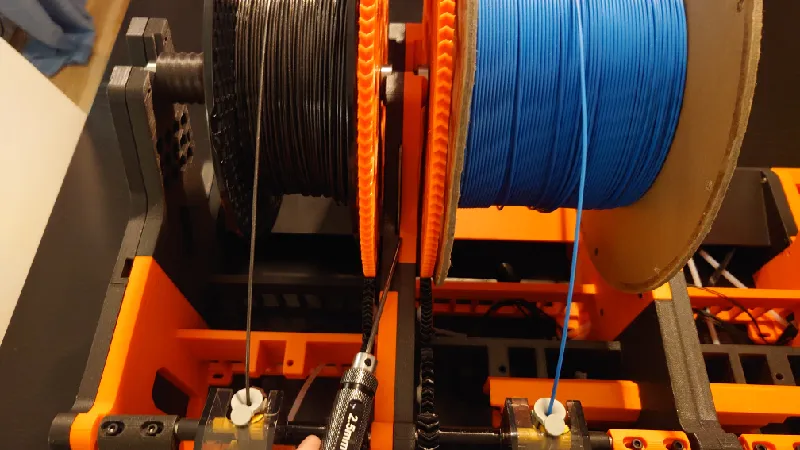
- Make sure you use 2.5 mm ID (inner diameter) PTFE tubing as per the BOM, if you use standard 2.0 mm ID it can be too tight.
“Can I use “AMS Savers / Filament Guides" with Mega Python?”
- Absolutely, all AMS Savers and so called Filament Guides are supported.
“Can I get the source design files in step format?”
- The main Mega Python AMS step files are not available publicly. However, some files are available in step format, please view the remix tab.
BOM - Bill of Materials
You can print Mega Python AMS in just about any filament you like.
I recommend placing the AMS next to the printer or wall mounting it.
Around (?) Kg of filament is required at the recommended print settings for the full build including four spool holders.
I've printed most of the test builds in Prusament ASA, PLA and eSUN PLA+, both brands and filament types work great. PETG is also a great option.
Filament
Fasteners
You need quite a few M3 socket heads but you don’t have to use them in all screw locations if you don’t want to. However, here is a list of all screw locations and specs:
- Left front side and left rear sides against first modules: 13 x M3-16 mm
- First middle module against left rear side (inside out): 2 x M3-16 mm
- Front and middle modules against each other: 36 x M3-16 mm
- Rear modules against each other: 6 x M3-16 mm
- Fourth front and middle modules against right side: 10 x M3-16 mm
- Fourth rear module against right side: 2 x M3-16 mm
- Right sides against fourth modules: 2 x M3-16 mm
- 28T and 29T gears against front modules / gear blocks: 8 x M3-16 mm
- Four adjustable feeder modules: 16 x M3-16 mm
- Four adjustable front roller holders against front modules / roller block: 8 x M3-25 mm
- Four front roller sleeves: 4 x M3-16 mm
- AMS filament hub / motor: 4 x M3-12 mm
- Four spool holders: 20 x M3-25 mm
- Attaching the main PCB holder: 2 x M3-12 mm
You can use 18 mm screws in place of the 16 mm screws in most locations in case you run out of certain screw lengths.
To summarize, the following M3 socket heads are needed:
- 6 x M3-12 mm
- 91 x M3-16 mm
- 28 x M3-25 mm
If you don't have any at home it's best to grab the kit below, it will have everything you need for this build and more:
Cable Extensions
For a full 4 spool bay Mega Python with RFID capability, two of the feeder cables (7-pin) and both RFID cables (8-pin) need to be extended. You can of course cut and splice in cables between the connectors as this will be the cheapest and possibly easiest depending on your skill, or you can buy extensions.
I use genuine Molex Picoblade 1.25mm cable extensions myself but you might find them cheaper on AliExpress or Amazon, keep in mind most are just male-male cables and not extensions though so those won't work. Search for Molex Picoblade 1.25mm.
If you want genuine Molex Picoblade, I recommend you get them from Mouser:
- Molex Picoblade 7-pin (225 mm extension, 2 pcs required)
- Molex Picoblade 8-pin (225 mm extension, 2 pcs required)
Keep in mind that with these extensions you must unpin and reverse the wire order else they will not function in the AMS. But it's very easy, I'll guide you through it in the assembly guide later.
Bearings
For the spool holders you also need 8 x 608-ZZ bearings:
You also need 12 x 693-ZZ bearings for the front drive gears sleeves and the 28T and 29T gears.
PTFE tubes
You need about 2 m PTFE tube to cut to length. I recommend the stock Bambu PTFE tube which has an inner diameter of 2.5 mm and an outer diameter of 4.0 mm. Go for the AMS Hub / Custom Cut which is a single piece 4 m tube.
AMS hub cable (1500 mm)
As Mega Python is quite large I recommend using the longer hub cable that comes with the AMS hub, it can be bought individually as well:
Optional
I highly recommend these Nano Coated Helical Extruder Gears from FYSETC, I use them for all my Bambu printers, they're inexpensive and offer a number of improvements of the stock gears:
I've also heard great things of the new BigTreeTech Panda Extruder but I've not tried it personally yet, you can get it including the Revo hotend as well:
Although not required these PEO/PEI/PEY bed sheets are great, I have most options myself, it gives a quite cool look on the first layer. There are a few shops offering different plates:
- Build Plate PEO/PEI/PEY Spring Steel Sheet (Super 3D)
- Build Plate PEO/PEI/PEY Spring Steel Sheet (IdeaFormer)
The Hex Tools are superb for any 3D printer, I've had mine for years. They are particularly useful for the Mega Python assembly.
Tools
I'm using a simple tool for cutting the PTFE tube, you can use a knife as well. I also use a fine file for cleaning up the parts. And if you go for the optional heated inserts, a soldering iron is needed. A short hex key for 2.5 mm is useful as well.
Warranty
Mega Python AMS does not void your warranty but be careful, especially with the AMS main board, use an antistatic wrist band. Although the mod is completely reversible and you can't tell the parts have been installed in Mega Python AMS, I take no responsibility and you're on your own. Be careful and take it slow, read this page twice before you start.
Support
All my designs and mods on Printables are free to use and remix. They have a non-commercial license. If you enjoy this or any of my other designs you can send me a small donation using the link below. Thanks :)
https://www.paypal.me/humebeamengineering
Before Printing Mega Python AMS
Make sure you dial in flow correctly before you start so that you are not overextruding. The problem then is you can't join the dovetail joints and assembly properly.
The Bambu Lab printers usually do a pretty good with automatic flow calibration but it's best to confirm flow anyway, sometimes it is inaccurate. There are ways to do manual flow calibrations directly from Bambu Studio and Orca Slicer so you can use those.
Once you have done that, print these dovetail test joints, more info here:
Print Settings
All parts print without supports and I recommend using 3 walls and an infill of around 15%. Print all parts in the direction I have set them.
There are individual 3mf files posted or you can download one of the full sets:
- coming soon
These can be loaded in Bambu Studio or you can print them directly from Bambu Handy.
Main parts:
Keep in mind that differently from the normal Python, Mega Python uses reverse direction for the two middle modules, this is for RFID support in all spool bays, so that the smaller 1 Kg RFID spools always are close enough to the RFID boards for a reading.
So it's important you print exactly these files.
- front-left-print-2pcs-1.01.3mf
- front-right-print-2pcs-1.01.3mf
- middle-module-print-4pcs-1.01.3mf
- rear-left-and-right-print-2pcs-1.01.3mf
- rear-pcb-print-1pc-1.01.3mf
- rear-motor-print-1pc-1.01.3mf
- main-pcb-base-print-1pc-1.01.3mf
- front-roller-holder-left-print-2pcs-1.01.3mf
- front-roller-holder-right-print-2pcs-1.01.3mf
- drive-gear-sleeve-adapter-print-4pcs-1.01.3mf
- feeder-module-print-4pcs-1.01.3mf
- gear-block-print-8pcs-1.01.3mf
- roller-block-print-8pcs-1.01.3mf
- front-gear-29t-hard-print-4pcs-1.01.3mf
- front-gear-29t-tpu-print-4pcs-1.01.3mf
- rear-gear-28t-hard-print-4pcs-1.01.3mf
- rear-gear-28t-tpu-print-4pcs-1.01.3mf
Notice: The the front and rear gears also have a “solid” one piece option if you don't have any TPU, see the Optional Prints folder. These gears are placed between the the large spool gear and the small drive gear and uses a 693-ZZ bearing pressed in. It then attaches through the front modules with an M3 socket head and the gear block on the other side, fully screw them in but ensure they do not bind. I recommend using TPU 95-98A, not softer.
Tip: I do not recommend printing the drive sleeves in TPU for Mega Python, the front and middle gears are enough in TPU. The drive gear sleeves are pretty long so it's good that they are in hard filament. But if you still want to, use rigid TPU like shore 98A.
Sides:
- left-side-front-print-1pc-1.01.3mf
- left-side-rear-print-1pc-1.01.3mf
- right-side-front-print-1pc-1.01.3mf
- right-side-rear-print-1pc-1.01.3mf
Spool holders:
- m3-wafer-head-gear-side-print-4pcs-1.01.3mf
- m3-wafer-head-top-side-print-4pcs-1.01.3mf
- spool-gear-135t-print-4pcs-1.01.3mf
- spool-holder-bottom-print-4pcs-1.01.3mf
- spool-holder-top-print-4pcs-1.01.3mf
- threaded-rod-print-4pcs-1.01.3mf
Notice: The threaded rod is quite tall and thin, make sure your bed adhesion is spot on. You may want to print these one at a time.
Use dry filament.
Assembly Instructions
If you've used Hydra before you should be familiar, it's very similar.
Notice: Some of the pictures in the instructions are from version 1.00. Version 1.01 assembles exactly the same except the feeder modules are tightened from below instead but both versions are covered in this guide.
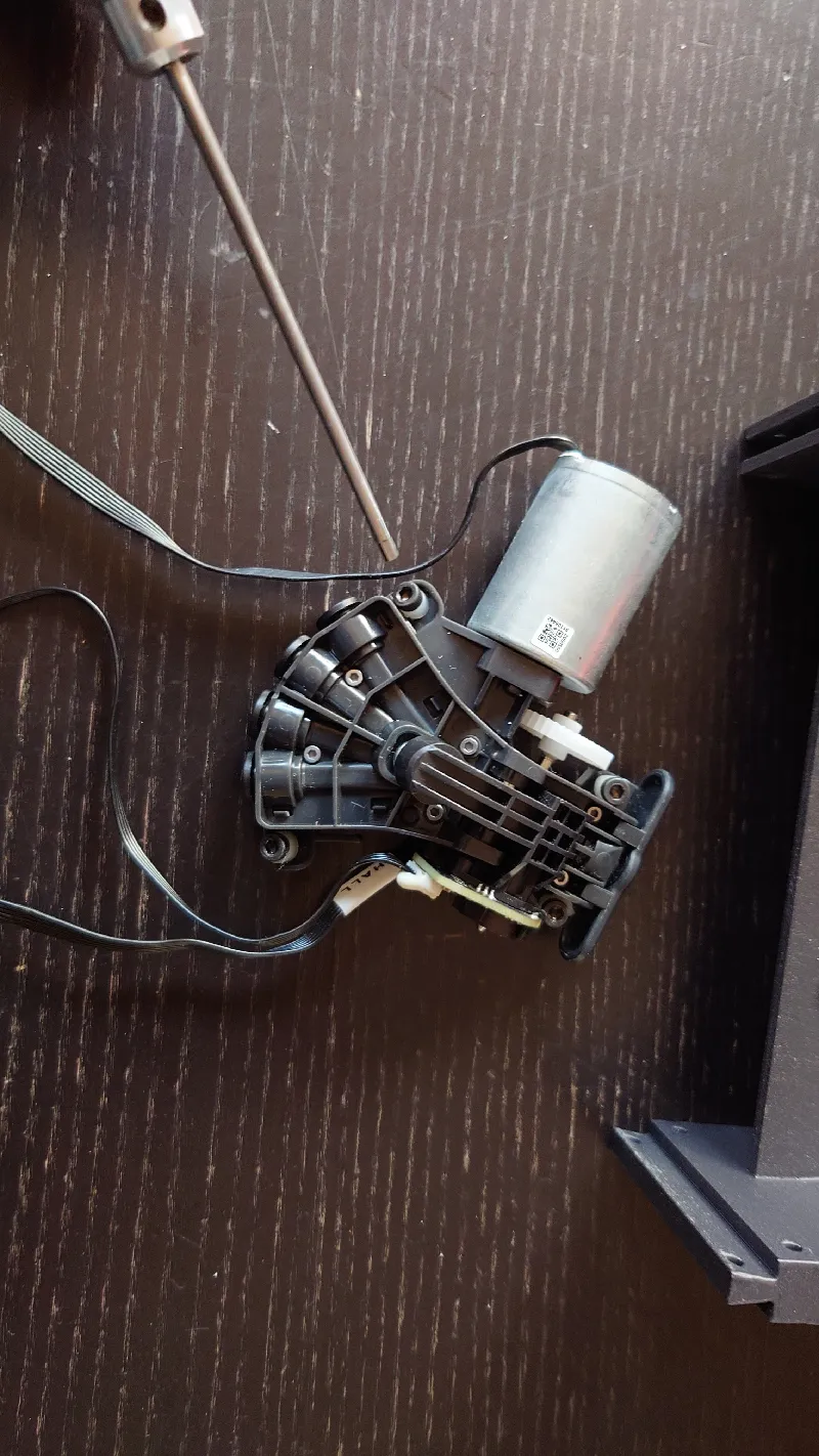
Remove the Bambu Lab AMS internals from the standard AMS, follow this guide, it's not difficult:
https://wiki.bambulab.com/en/x1/maintenance/replace-the-ams-main-frame
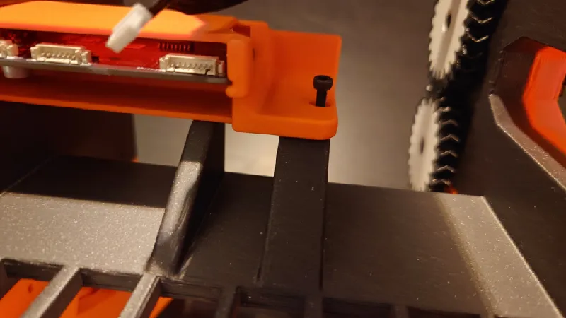
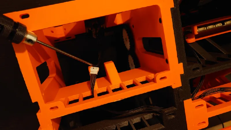
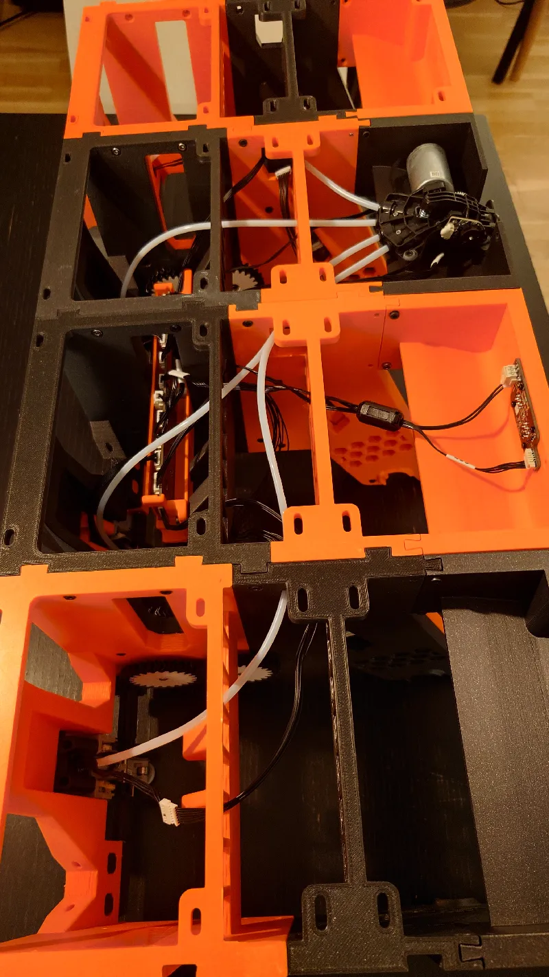
Be sure to mark all cables and connectors before you remove them. I recommend marking each connector on the board and corresponding cable with a thin permanent marker pen as pictured below:
Precaution: Always wear an antistatic wrist band when working with electronics.
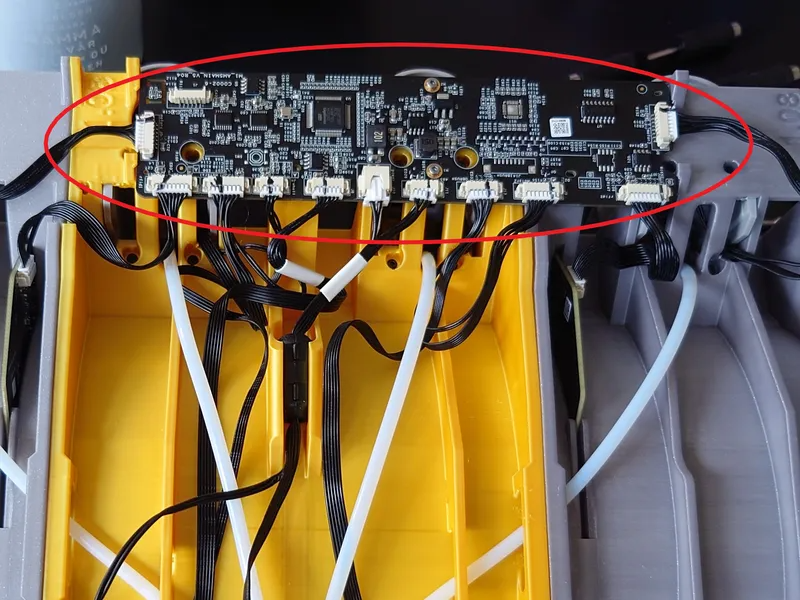
You should also remove the small rear PCB from the AMS box, it sits with four small black screws. Take the board and the screws, they're needed for the Python build.
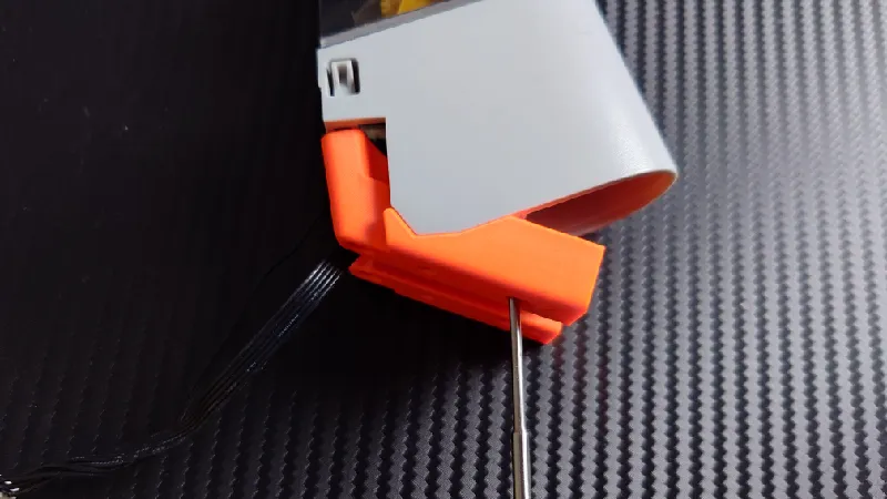
Front Rollers
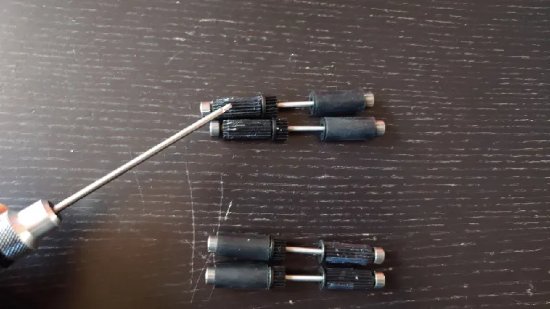
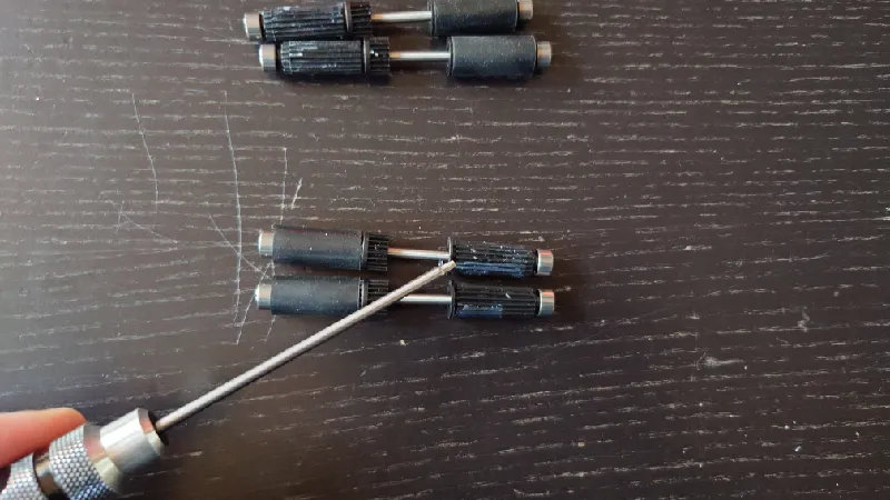
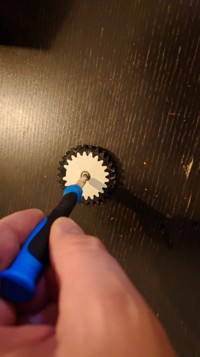
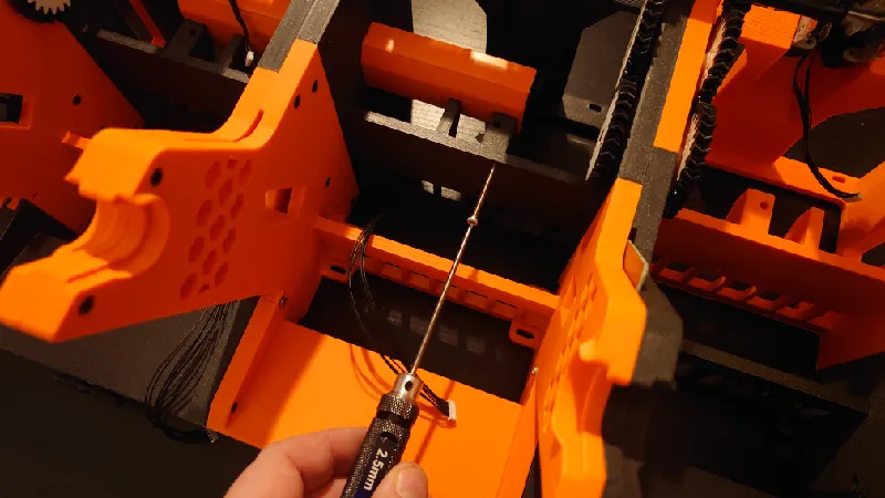
Once that is all done, the first step is to remove the rubber sleeve from the gear side of the front rollers, meaning the side with the gear for two of the front rollers.
It's very easy. Just insert a thin pin between the rubber and the plastic casing and rotate the pin all around it. I'm using my 1.5 mm hex tool, it takes less than 30 seconds to do one. Save the rubber sleeves in case you revert to stock later.
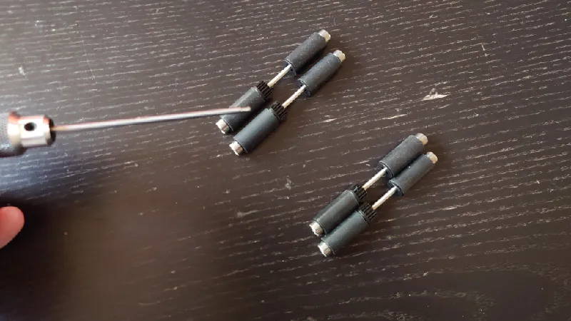
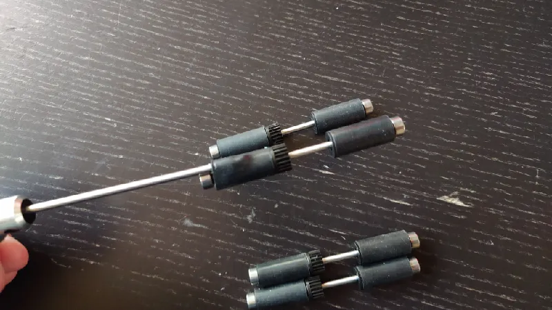
Next, do the same but for the passive side of the front rollers, meaning the side without the gear for two of the front rollers.
When you are done it they should look like this, you can see the rubber sleeves are removed for the gear side of two of the rollers and from the passive side of two of them:
Front Rollers
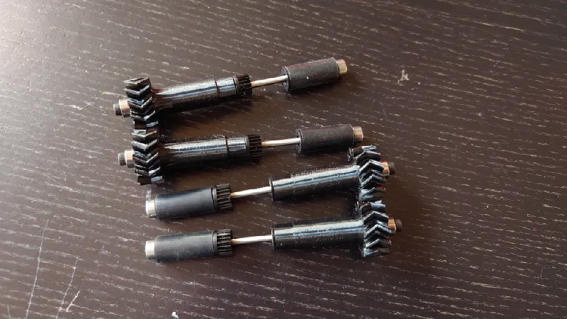
Continuing with the front rollers, grab the front roller sleeves (drive-gear-sleeve-adapter-print-4pcs-1.01.3mf) and install it by pushing it fully in. It's a good idea to hold the plastic casing so it doesn't slide off the steel shaft as it's just pressed on.
I recommend printing the drive gear sleeves in hard filament such as PLA, PETG or ASA and not flexible TPU, use TPU just for the intermediate gears. TPU will work too but if so use fairly rigid TPU with a shore rating of 95A or 98A.
You shouldn't need to use any glue but if you want to, use silicon glue that's non-permanent.
Next, take a M3-16 mm socket head screw and a bearing and screw it to the side of the roller.
Screw it in fully then back off a quarter of a turn so it spins freely.
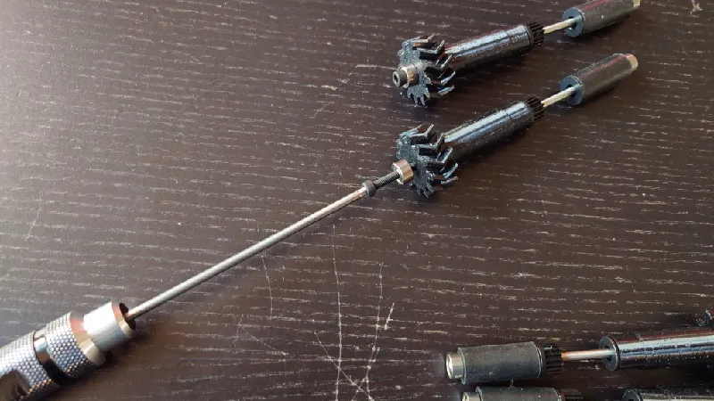
Your full set of rollers should now look like this:
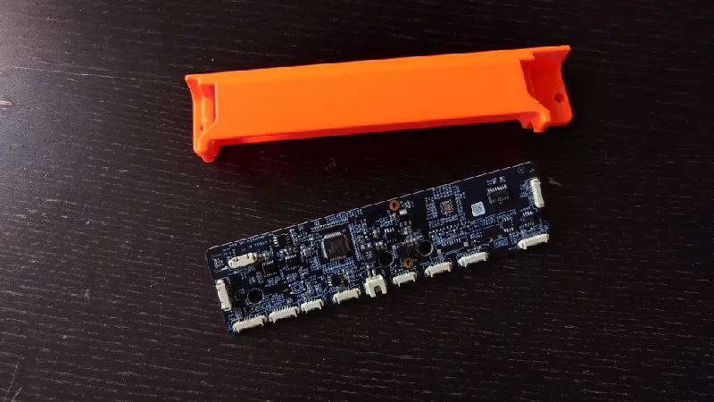
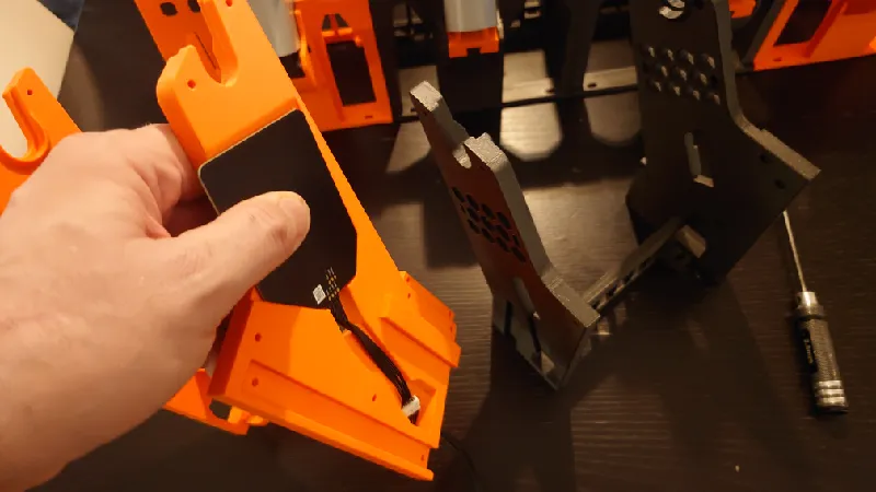
AMS Main Board
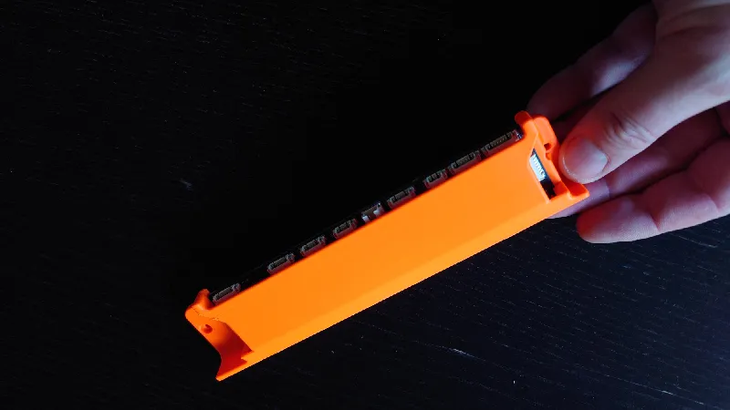
The next step is to insert the main AMS board into the holder (main-pcb-base-print-1pc-1.01.3mf). Take notice of the board direction.
It's just friction fit. Make sure to press down both sides at the same time so it doesn't get inserted at an angle because then you will have issues pressing it fully in. If it sits too loose you can secure it with a dab of silicone glue.
PCB Module
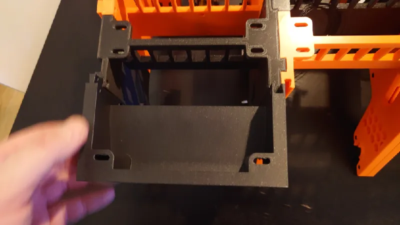
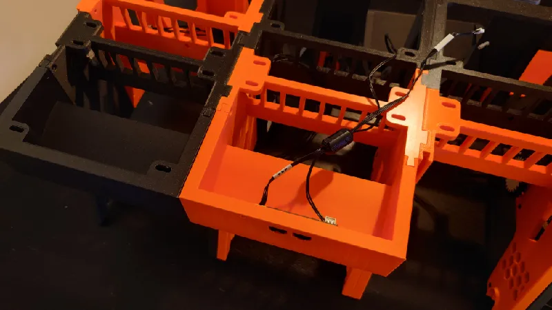
The next step is to screw the small rear PCB to the PCB module (rear-pcb-print-1pc-1.01.3mf). Use the same four screws that attached it to the stock AMS box.
Take notice of the board direction, the cable connectors should face the “roof” of the printed part. The ferrite core (black round plastic container) you should just leave “hanging” in the air, there is no socket for it and it's not needed.
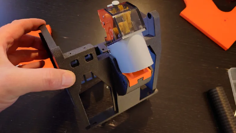
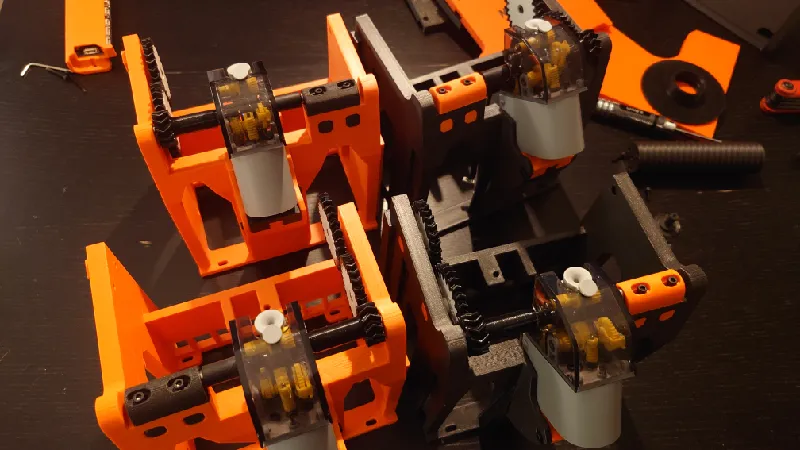
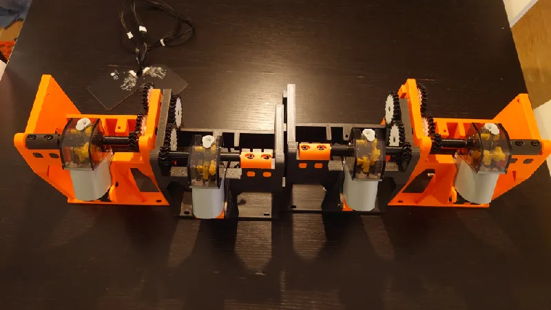
Motor Module
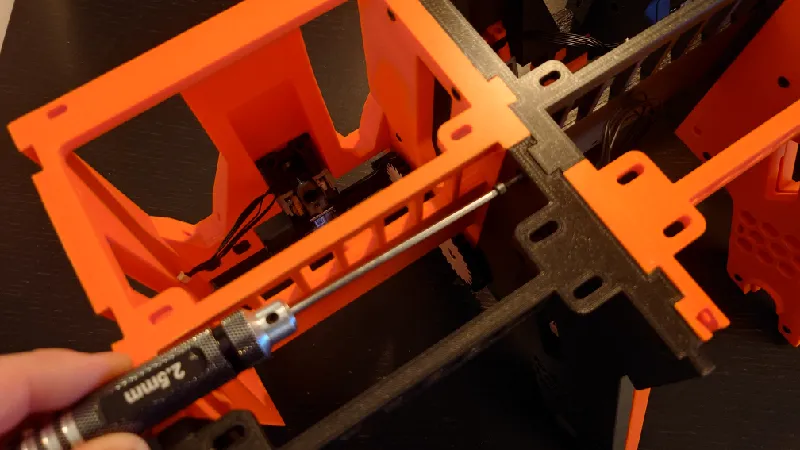
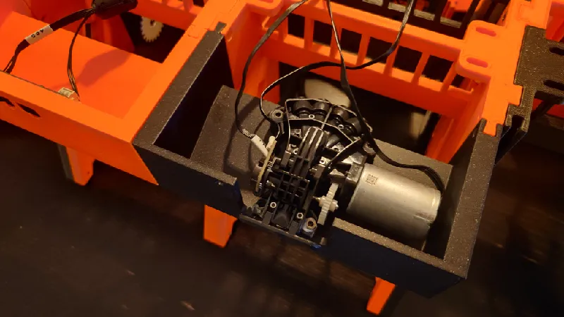
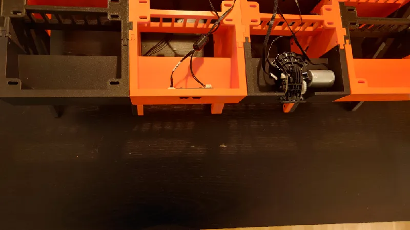
Next, mount the motor / AMS filaments hub motor in the Motor Module (rear-motor-print-1pc-1.01.3mf). Remove the four stock screws and install it in the module with four M3-12 mm socket head screws. You can keep or remove the white rubber bushings, it doesn't matter.
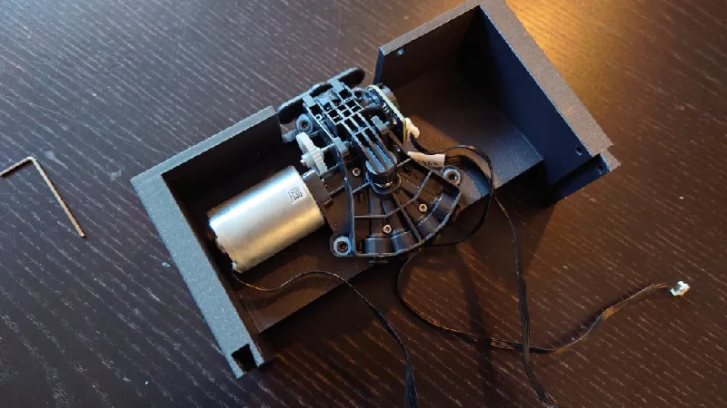
Make sure it's fully screwed in so the module sits flat on the table without rocking.
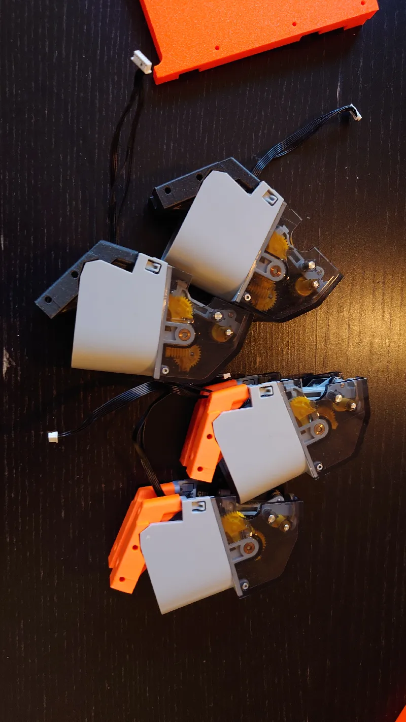
Feeders
Next it's time to install the four feeders in the feeder modules. Use the four stock black screws for each one.
Next, use four M3-16 mm socket heads with the feeder module washers in between. The chamfered side of the washers should face the feeder.
Do not fully screw the socket heads in, leave a gap of around 6-8 mm so they can be slid into the front module later before being tightened.
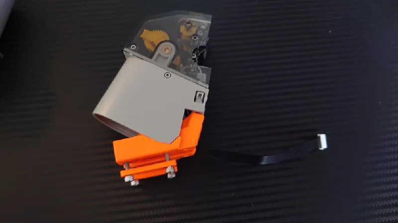
Do the same for all four feeders.

For version 1.00 they look a little different as they have attachment / adjustment holes on the sides instead and do not use the feeder module washers:
Spool Holders
Unlike the stock AMS where the spools run on top of rollers, Python uses spool holders that are compatible with all sorts of spools and it uses geared delivery for high torque. The spool holders are compatible with an inner diameter / hole diameter of the spools between 38 and 85 mm, which is probably 99% of all spools.
But if you have even bigger inner diameter of your spools it's no worry, there are step design files available of these (check the remix tab) so you can make your own.
You can also use the Adaptive Spool Holder if you like, it's fully compatible.
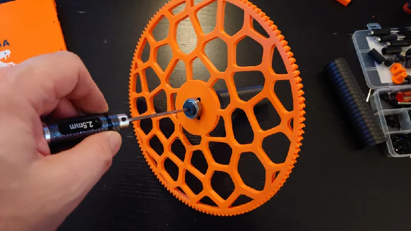
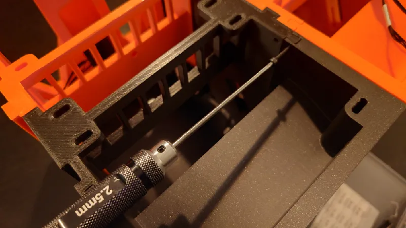
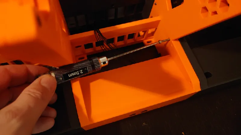
Start by screwing in the three outer M3 socket heads. The length isn't very important but around 25 mm is good.
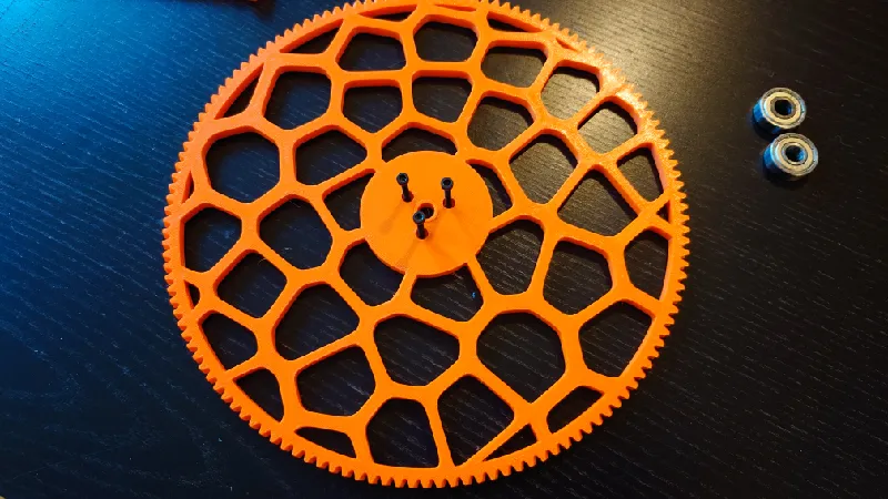
Have them go through the spool gear by a few mm so it's easier to align with the threaded rod.
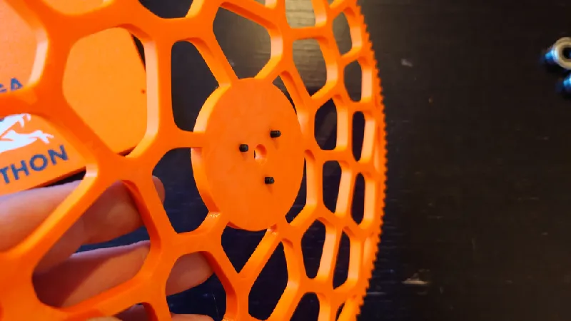
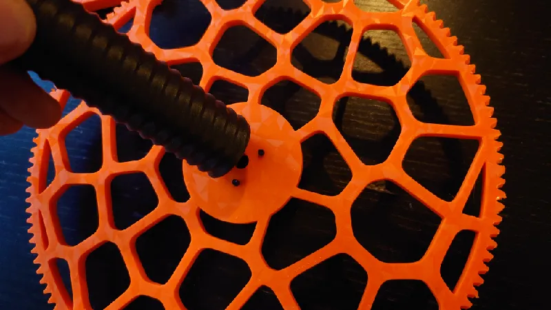
Then just screw it fully to the threaded rod.
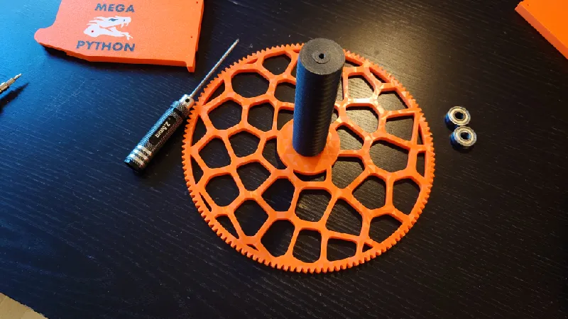
The next step is to attach the 608-ZZ bearings using the printed parts and M3 socket heads. The taller “wafer head” goes on the spool side (m3-wafer-head-gear-side-print-4pcs-1.01.3mf) and the shorter wafer head goes on top of threaded rod.
The reason it's taller is it goes through the spool gear as well which is 6 mm thick.
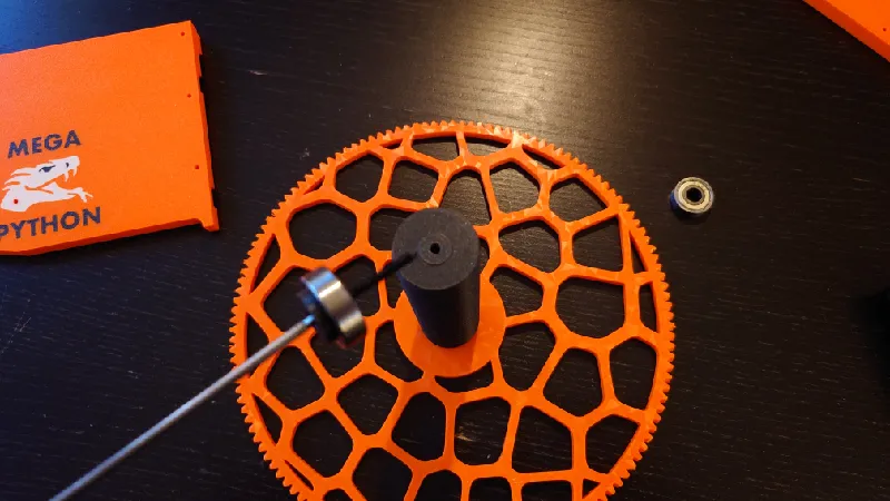
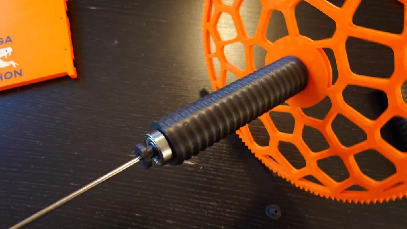
Install the 608-ZZ bearing on the other side as well.
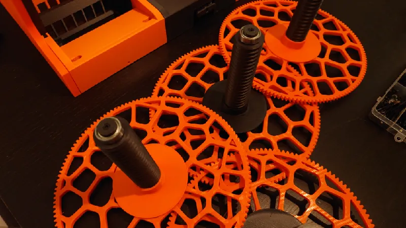
Next, screw on the bottom of the spool holder. This part is important to keep the spools centered on the spool holder but it's also important so that when you install a spool and tighten it, you tighten (mostly) against the rod and not just the large spool gear (thus bending and deforming it).
If you use small sample spools or other very narrow spools you can use a spool bottom (check optional print files) with a thicker bottom (5-15 mm) to align it in front of the feeder.
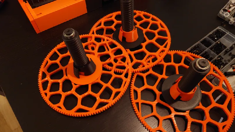
Pictured below is the Adaptive Spool Holder setup which uses bottom part to offset the spool a fraction from the gear as well as a spring to center the spools but the principle is the same with the included spool holders, only that they don't automatically center the spools. Use whichever version you prefer.
Front Modules
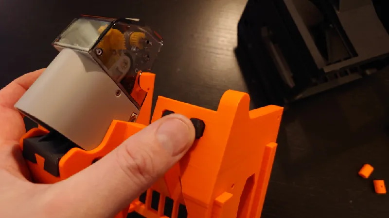
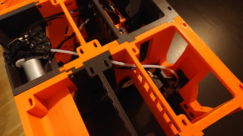
Install the feeders and feeder modules in the front modules, guide the cable in the middle slot and just slide the modules together.
The feeders need to mesh perfectly with the front roller gears but I will instruct this later, for now you can just have the feeder in the middle position without tightening the screws.
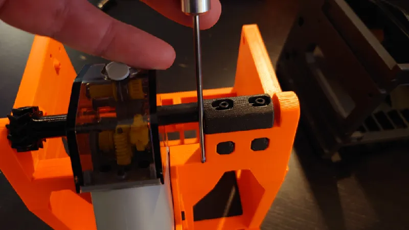
For version 1.01 the feeder modules are fastened with four screws from below (Picture from standard Python, identical feeding module mounting). Do not tighten yet.

For version 1.00 the modules attach from the sides:
Do the same for all four front modules.
Press in the roller blocks (roller-block-print-8pcs-1.01.3mf) in the front feeders, do this for all four front modules.
Install the front rollers and front roller holders. Use two M3-25 mm socket heads for each.
Take notice that the front roller holders are different (front-roller-holder-right-print-2pcs-1.01.3mf and front-roller-holder-left-print-2pcs-1.01.3mf) depening on which module you are working on, use the one that aligns with the shape on the front module corner.
Set a low tension of the front roller holder. A good rule of thumb is to have it aligned with the column below it. The roller should spin fairly easily.
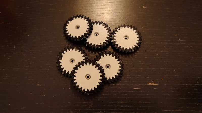
28T and 29T Gears
The purpose of the gears is to act as intermediate gears between the small rollers / drive gear and the large spool gear.
I recommend printing the gears in two parts. The outer part printed in TPU and the inner part in hard filament but if you don't have any TPU you can use solid 28T and 29T gears instead, see the optional printed parts folder.
For these you use a 693-ZZ bearing and M3-16 mm socket head each.
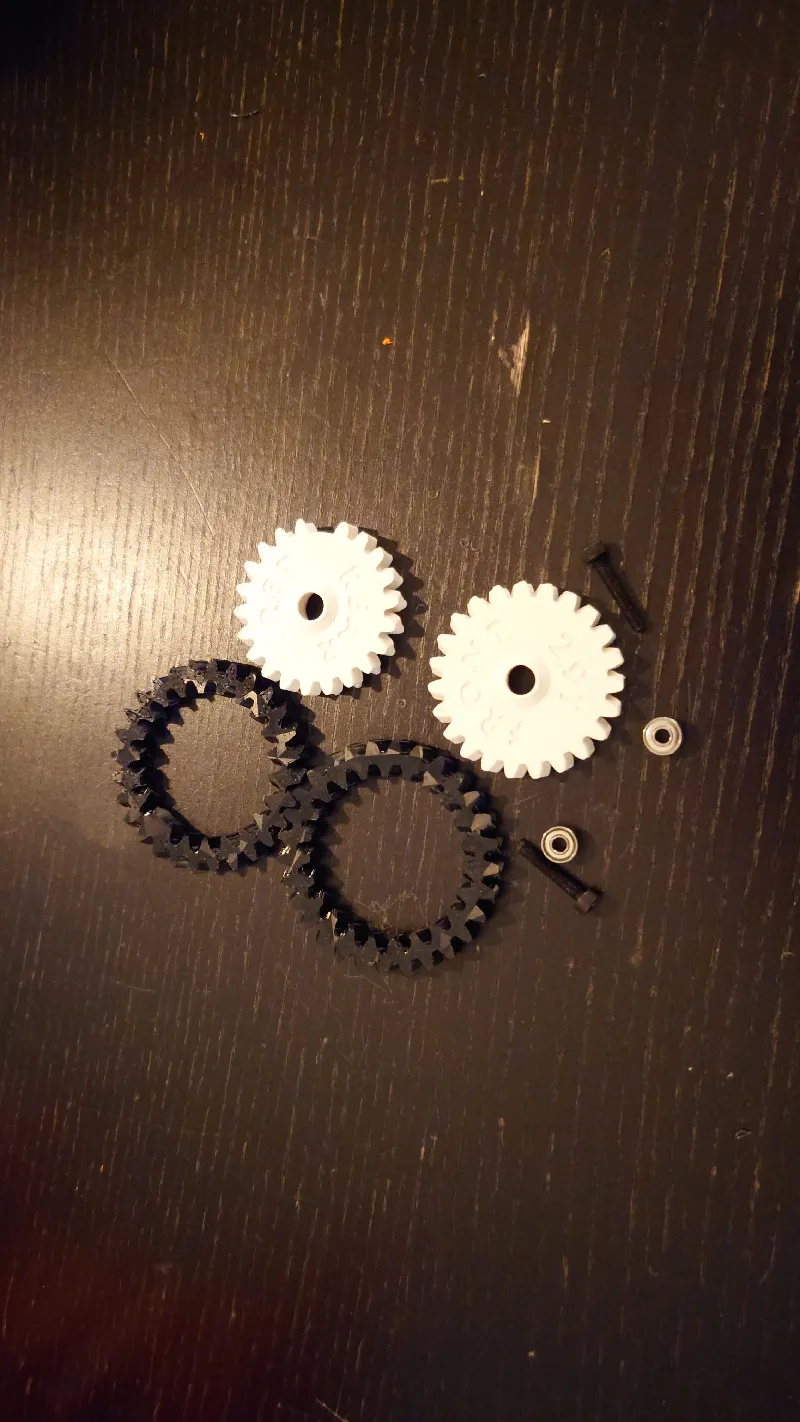
Start with the 28T “rear” gear. This is the gear that has a missing tooth in the inner gear set, it's designed this way so you don't mix up the gear parts.
The reason the rear gears are 28T and the front gears are 29T is to distribute any potential wear of the gears.
Slide over the printed TPU gear part over. Take notice of the inner gear direction, it can only fit one way.
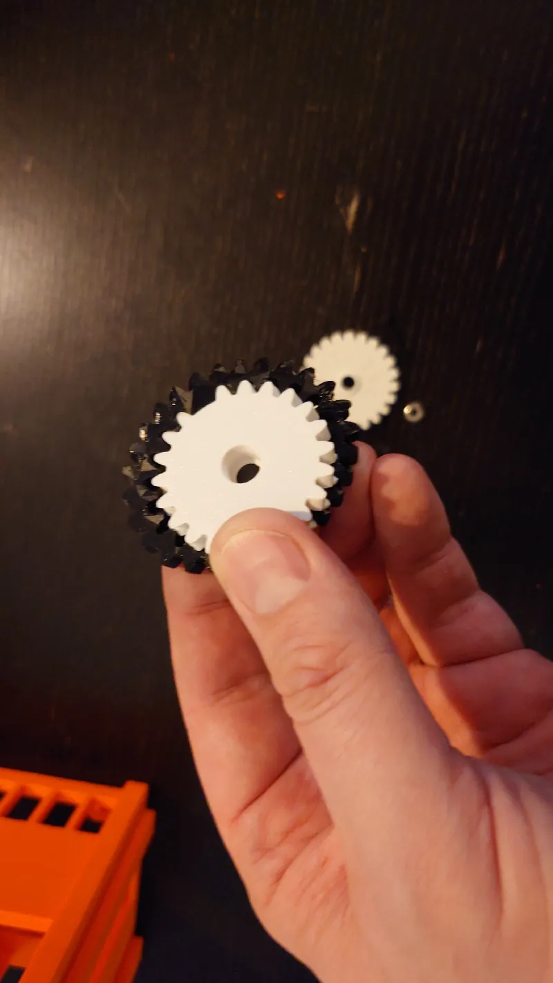
Next, press in a 693-ZZ bearing fully to the bottom.
Next do the same for the 29T front gear.
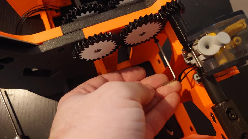
Next attach the gears to the front module, the 29T front gear is closest to the feeder and the rear 28T gear is closest to the spool holder.
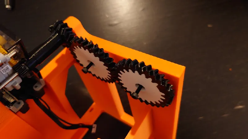
Place the gear blocks and tighten the M3 socket heads at the same time. Hold the gear block steady with a finger as you screw in the socket heads.
Screw them fully in then back off half of a turn so they spin freely but do not wiggle.
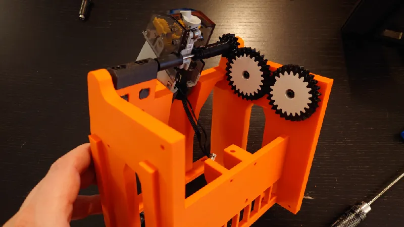
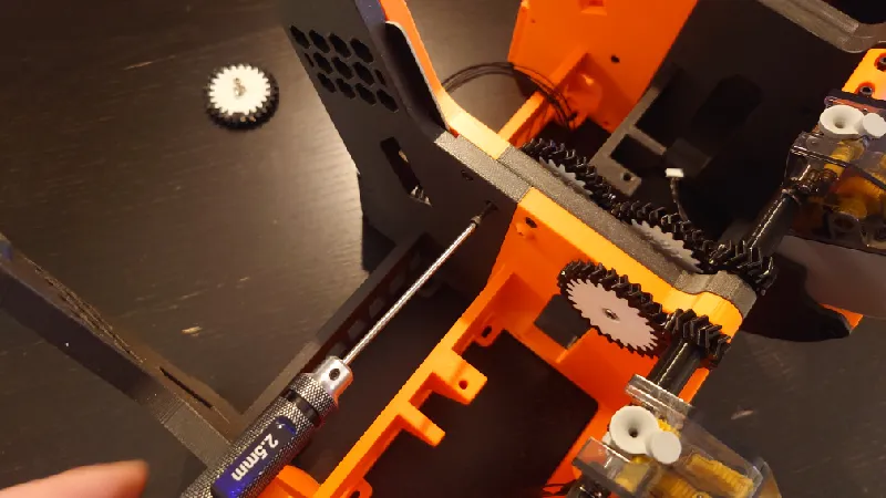
Install the TPU gear for the remaining six gears and press in the bearings for those as well:
Install the drive gear holders and front and rear gears for the rest of the front modules:
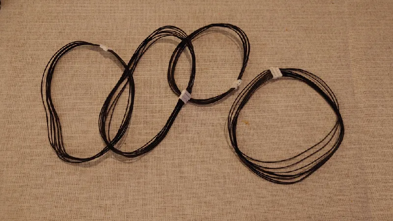
Feeder and RFID cable extensions
As Mega Python is so large, two feeder cables and both RFID cables must be extended, else they will not reach.
If you want genuine Molex Picoblade, I recommend you get them from Mouser:
- Molex Picoblade 7-pin (225 mm extension, 2 pcs required)
- Molex Picoblade 8-pin (225 mm extension, 2 pcs required)
Keep in mind that with these extensions you must unpin and reverse the wire order else they will not function in the AMS.
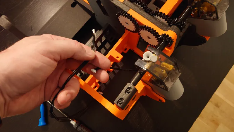
To unpin and reverse the wire order, lift the plastic tab holding the pin in the male connector and then pull the cable carefully straight out. Do the same for all the pins.
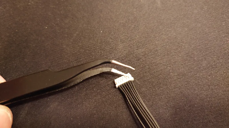
Once you get to the last cable in the connector, keep track of it, this then of course should be placed in the first slot of the other side of the connector.
Ensure the “hook” of the pin is intact and sticking up from the pin, else you can just carefully bend it up with a fingernail.
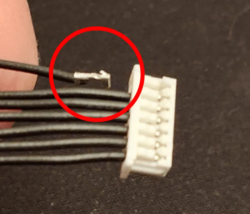
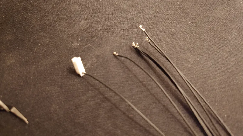
Now insert the cables in reverse order then press down the plastic for each one.
The hook of the connector should be up as pictured above.
Pull on it to ensure it's firmly in place.
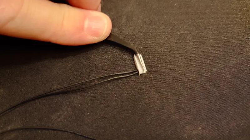
Do the same for all pins in the cable. One you are done, test the extension cable by plugging it into itself.
It should now be a “straight” extension, you can see this by following each cable in the extension, it should not be twisted.
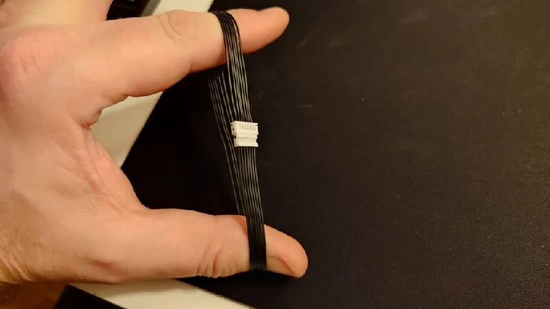
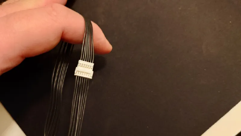
You should now have a set of two feeder cable extensions and two RFID cable extensions as pictured:
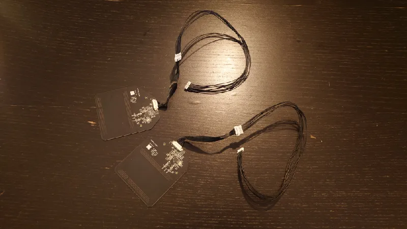
RFID Boards
Install the extensions in the RFID boards:
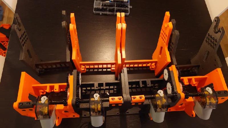
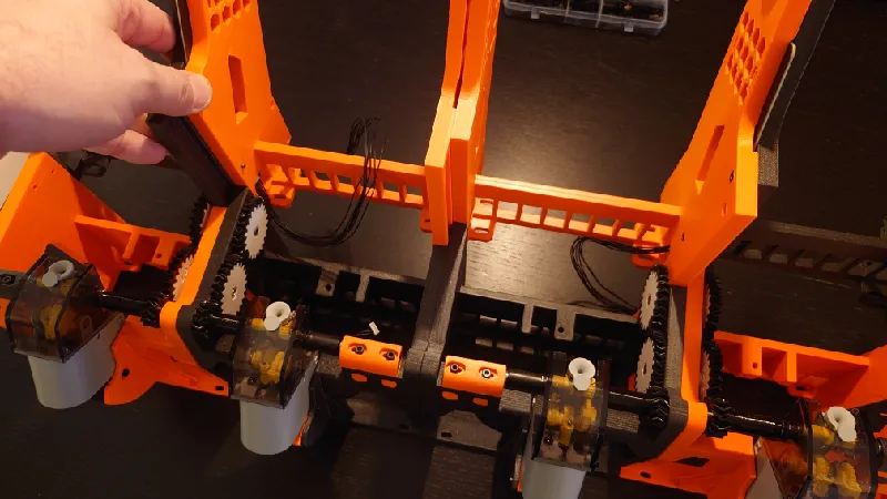
Front Modules
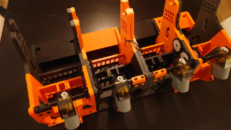
Join the four front modules together by sliding the dovetails together.
It's important that the small gears sit in the middle as two sections of Mega Python have reverse spool direction. It should look exactly like below:
Start with the leftmost module then continue to the right. The dovetails for the front modules are male on the right side and female on the left so join them as pictured:
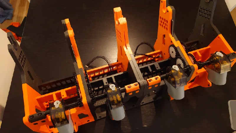
All four modules joined:
Middle Modules
Place the middle modules. They are identical so it doesn't matter in which order they are.
The RFID boards are placed in the socket like this of middle module one and three. They are just press fit against the next module next to it.
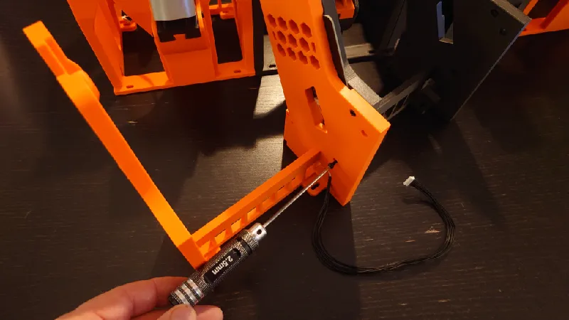
Place it exactly like this then carefully slide the modules together, the RFID cable and extension should sit in the slot and threaded through:
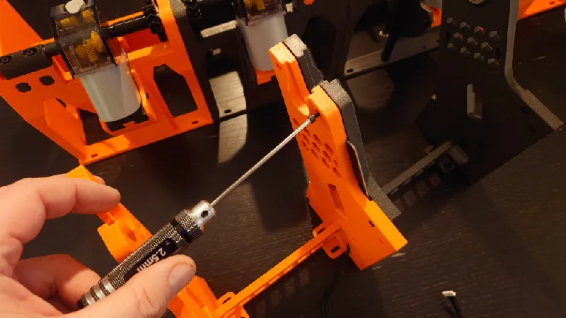
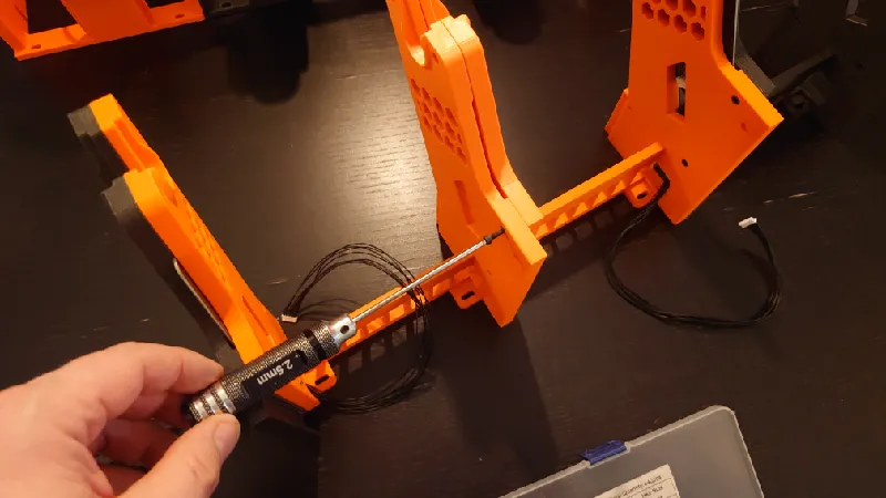
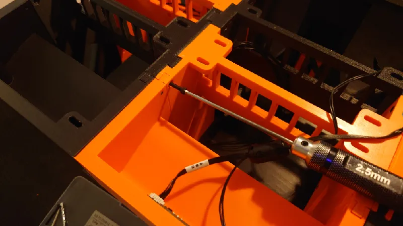
It's a good idea to tighten the sections immediately so use four M3-16 mm socket heads to join them.
Screwing the parts together is quite simple but time consuming, just remember all socket heads go from the socket head cutout side in. They socket heads don't go fully in but are partially exposed in most areas.
First M3-16 mm goes here:
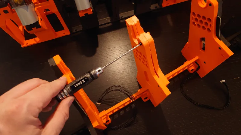
Second:
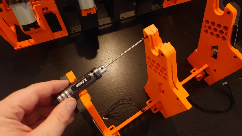
Third:
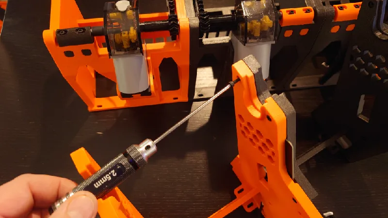
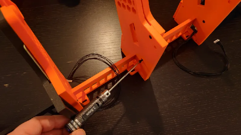
Fourth:
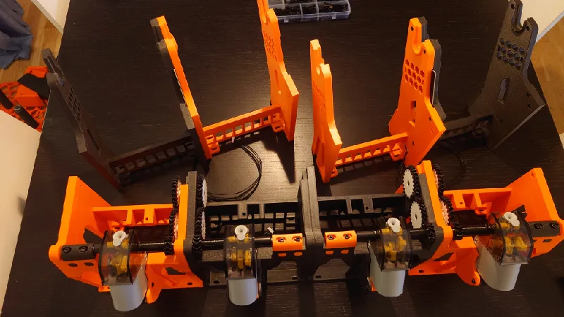
Do the exact same thing for module three and four.
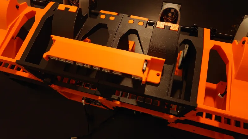
You should then have the rear modules like this, with the RFID boards in the middle:
Join the middle modules together with four M3-16 mm screws:
First socket head here:
Second:
Third:
Fourth:
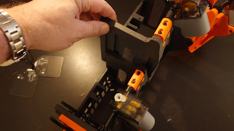
Joining Front and Middle Modules
Now with all four middle modules screwed together you can join them with the front modules.
Due to the fairly complex dovetail system you can't really easily join the modules together separately but they should go in all at once.
Next, install all socket heads. One M3-16 mm socket head should be used for each accessible screw hole from the socket head cutout in.
You don't really need to use screws in all locations if you don't like, the structure is super sturdy as is but the ones on top of the spool holder columns must be secured with socket heads as there is no dovetail there (should already be in place if you followed the previous steps.
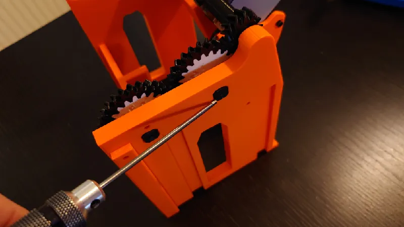
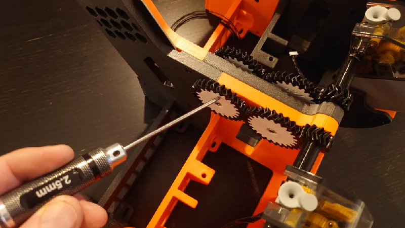
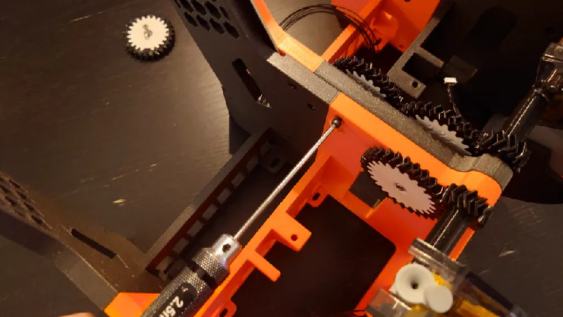
The screw location hidden by the middle gears are optional as there is a big dovetail going all the way to the top there and it's very sturdy but if you like you can remove the rear gear and add one M3-16 mm screw there and then screw the gear back on.
Continue with the rest of the screw locations. Like I said, the number of screw holes are overkill and you can skip quite a few if you like.
There is one screw location below the front 29T gear:
One here, joining middle and front modules:
Then you can flip the whole Mega Python upside down and do the rest.
There is one here between each front module:
And one here:
Continuing with the middle modules, there is one joining the middle and front modules here:
Rear Modules
Install the rear modules. The left and right rear modules are identical with the PCB and Motor modules place in the middle.
The rear modules slide in and are then secured by socket heads.
Be careful with the female dovetails and slide in the correct angle as they are quite thin.
But once tightened down they are strong so don't worry.
Next to it, place the PCB module:
Then the motor module:
And finally the other side rear module. All four in place:
Start screwing the rear modules to middle middles. Go from the side with the socket head cutout in. Use M3-16 mm socket heads here as well. In fact, that screw length are used in most spots.
I will not show details of exactly all spots but wherever there is socket head cutout a screw should be used:
Some screws are more easily screwed in place from above:
Nearly there. Only the PCB holder and connecting cables left to do.
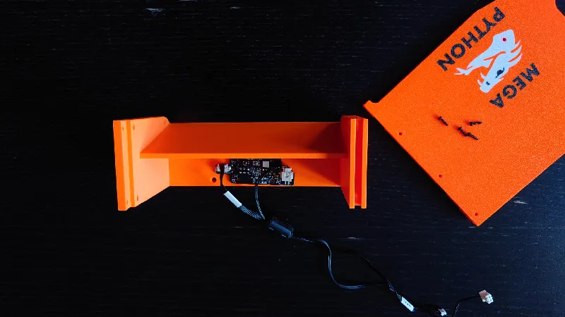
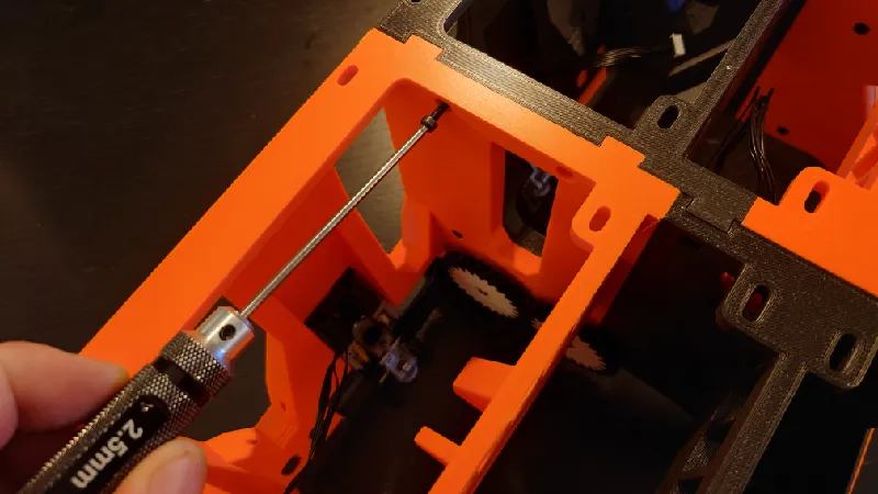
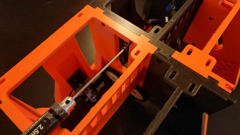
Main PCB Holder
The PCB holder is placed in this direction but in the middle of the assembly. It is placed centered between module two and three.
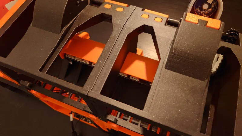
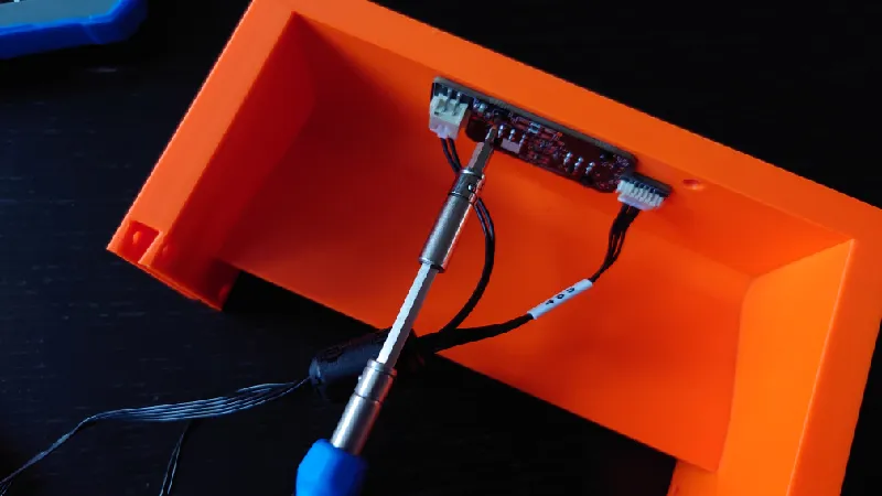
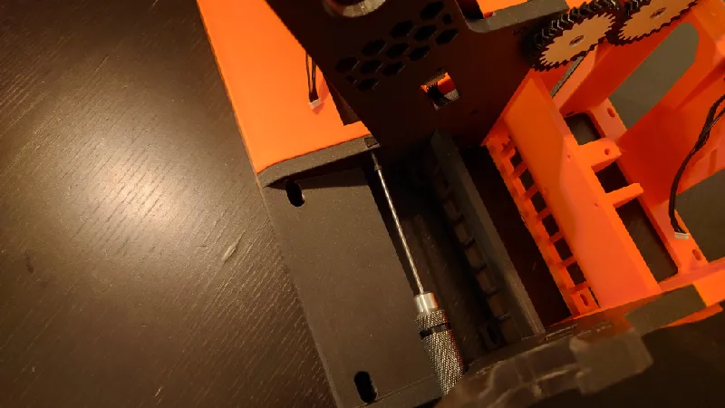
The PCB holder is screwed to the front modules with two screws and here is the bad news, it's quite difficult to screw it in place.
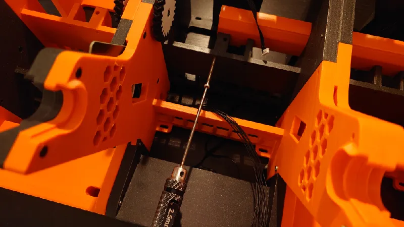
I recommend using a short hex key here, use M3-12 mm socket heads:
Optionally you can use 35 mm socket heads from the rear and M3 nuts on the other side, it will be easier.
Connect feeder and RFID cables
For the leftmost module (front module one), connect a 7-pin extension cable.
Do the same for the feeder for the fourth module.
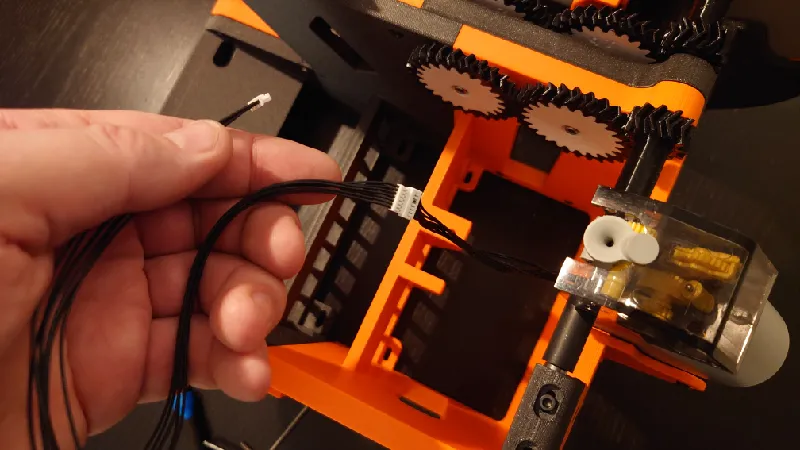
For the first module, route the extension of the feeder cable through.
Connect the first feeder to the side of the PCB here:
Route the first RFID extension cable trough from the board connect it here.
Connect the second feeder module here:
Connect the third feeder here:
Connect the second RFID cable here:
Connect the fourth feeder cable here to the side of the PCB:
Connecting the rest of the cables
By now you should already have connected the four front feeder cables and the two RFID board cables. Let's do the rest.
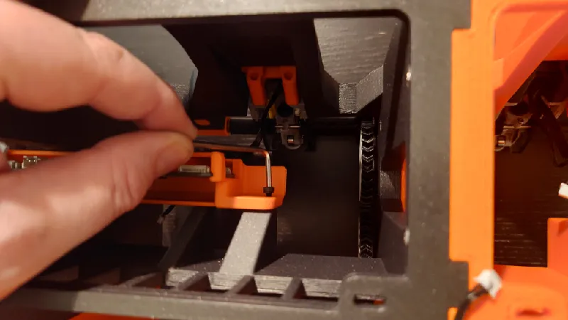
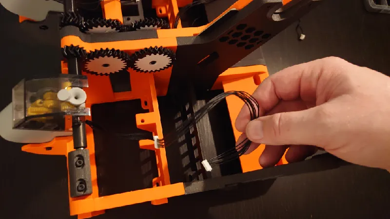
Start with the motor cable. Guide the cable through the holes, this is the suggested route.
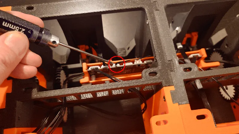
Then connect it here on the PCB, third plug from the right.
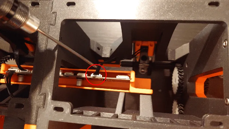
Next route the Hall sensor and Speed measurement cables from the internal AMS filament hub.
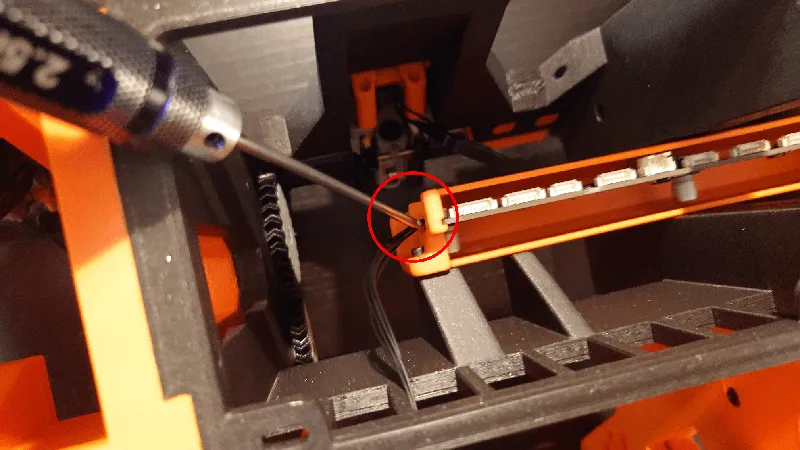
The Speed measurement cable goes here (circled), it's the third plug from the left:
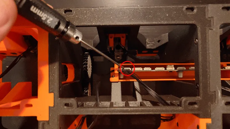
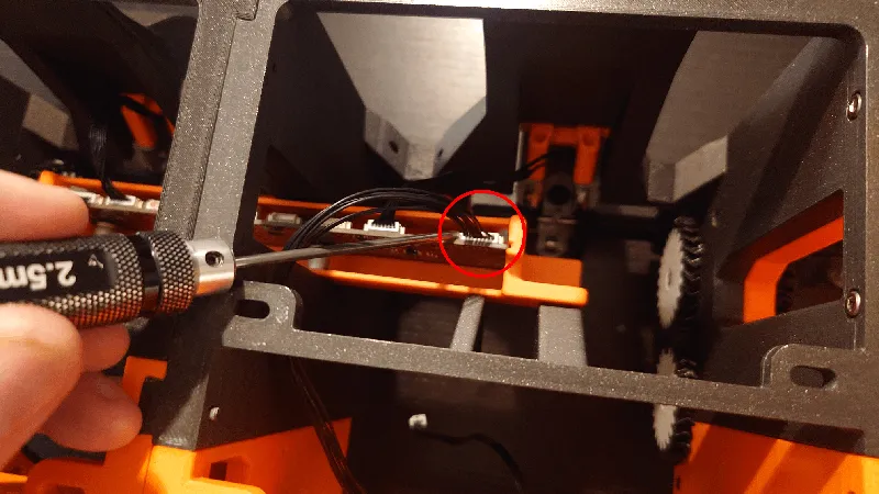
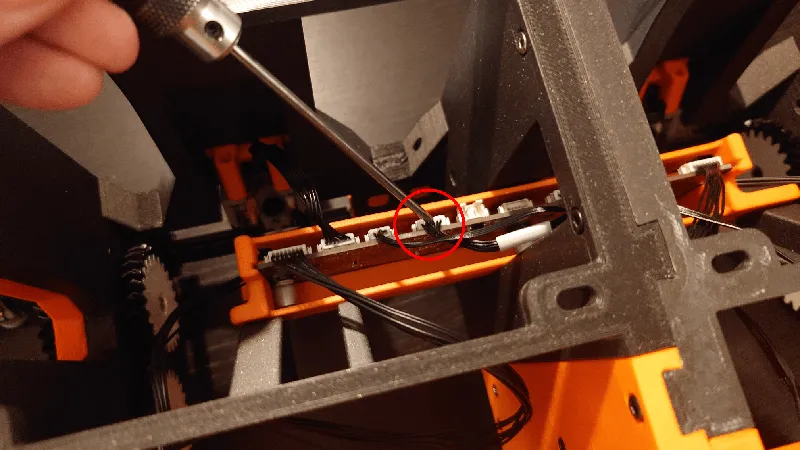
While the Hall sensor cable goes here (fourth plug from the left):
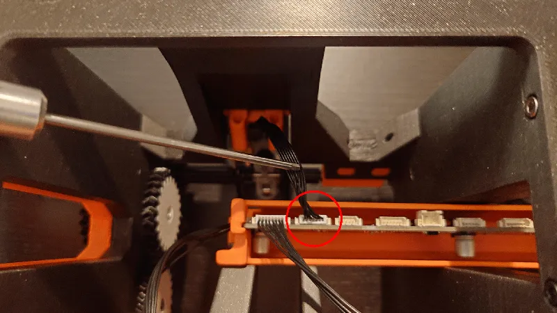
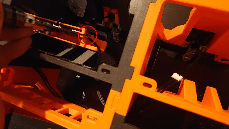
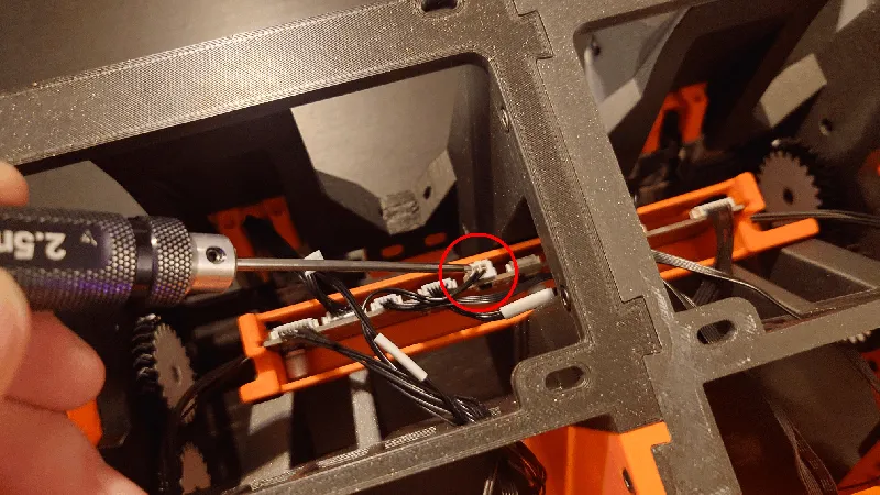
Next, guide the cables from the small rear PCB through.
Connect the Power cable here, fifth plug from the left:
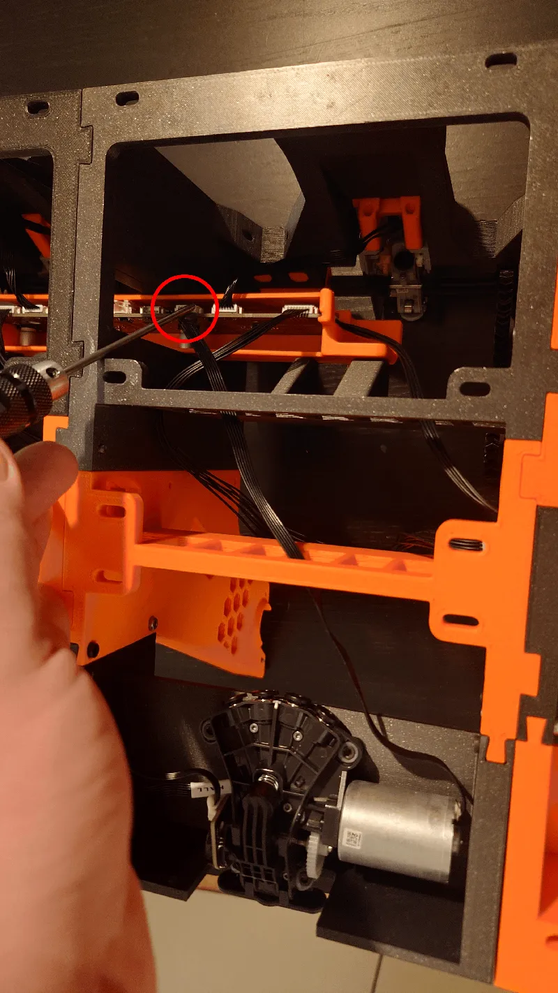
And the Bus cable here, sixth plug from the left:
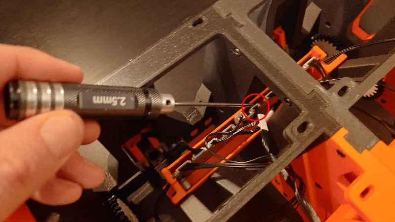
That concludes the cable installation, everything is now plugged in correctly.
Cut PTFE Tubes
The stock PTFE tubes are too short so get a new set from Bambu Lab or from AliExpress.
I use a tube cutting tool but you can use a knife if you like.
Guide through the tube as per below then connect it to the first feeder. Pull on it to ensure it's locked in place.
It's important that the tubes are not too long as this can cause more bend on them than needed. Not too short too of course.
A good rule of thumb is to stretch it then add 10 mm or so like the picture below then cut it.
First feeder PTFE tube done:
Do the same for the rest of the tubes. There are multiple ways to route your PTFE tubes,
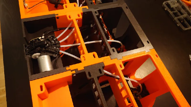
There is no right or wrong but this is the suggested routing:
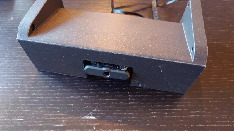
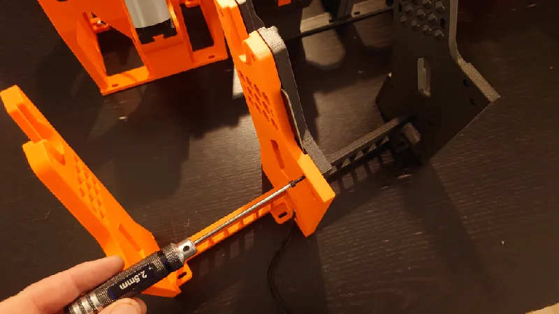
Installing the sides
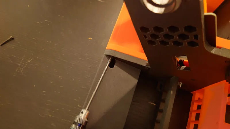
Slide in the left hand sides. Both front and rear left side slides in from below.
Then use M3-16 mm socket heads for all screw locations with an indent.
The right side front also slide in from below while the rear slides in from the top.
Again, use M3-16 mm socket heads for all screw locations with an indent.
Finally, secure the right sides from inside out as well, again with M3-16 mm socket heads.
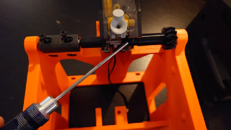
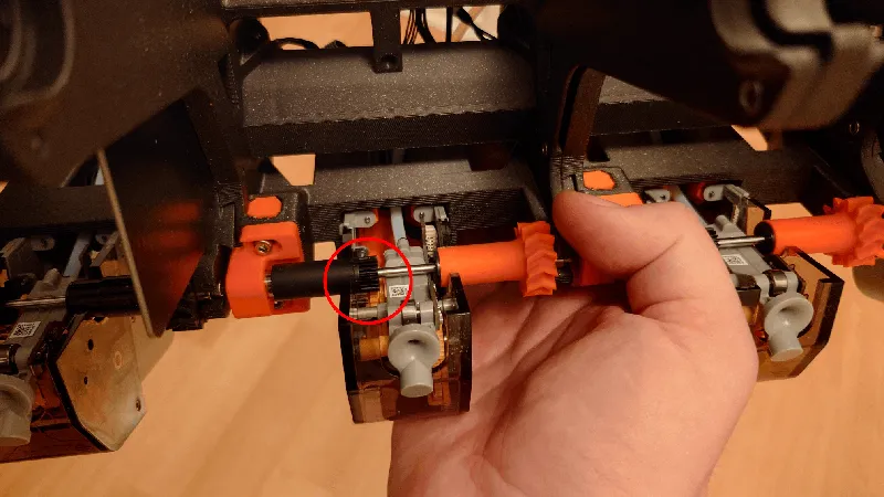
Adjust the Gear meshing / retraction
A good rule of thumb is to have the feeder as close to the roller as possible without the roller grabbing the yellow gear while you rotate the roller by hand. It should not grab in either rotation. See the area circled below.
The pictures below are from the standard Python but the feeder modules and adjustments are identical.
Adjust it so it just grabs it then back off a fraction:
For version 1.01 the feeder modules are fastened with four screws from below.
For version 1.00 the modules attach from the sides:

All done!
- Make sure there is not too much tension on the rollers / drive gear sleeves, they should spin with very low rolling resistance. If not, adjust the drive gear holders. Too much friction can cause issues when the AMS is retracting the spool.
- Make sure you center and fully tighten the spool holders before printing. The spool holders do a pretty good job of auto centering the spools when tightening but it's a thing to keep in mind. You can also use the Adaptive Spool Holder that auto tightens the spools on the rods.
- When loading the spools, ensure you align the spool holder on top of the front roller sleeve. Before you start a print, ensure the gears mesh and so it doesn't run outside it.
- Also when using small small spools, use a thicker spool holder bottom so it lines up with the middle of the feeder.
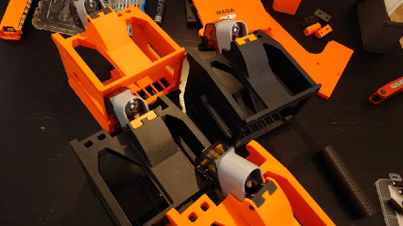
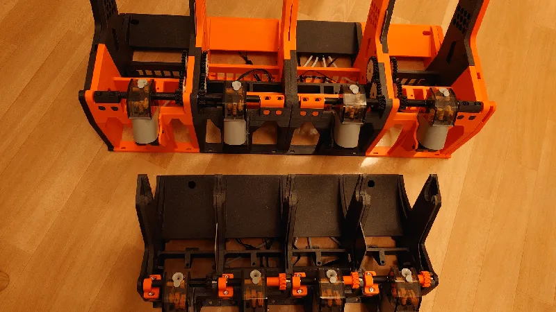
Pictured here is a spool of Prusament 1 Kg and a cardboard spool of Polymaker Polyterra 3 Kg.
Mega Python (rear) vs standard Python (front).
Tags
Model origin
The author marked this model as their own original creation.


