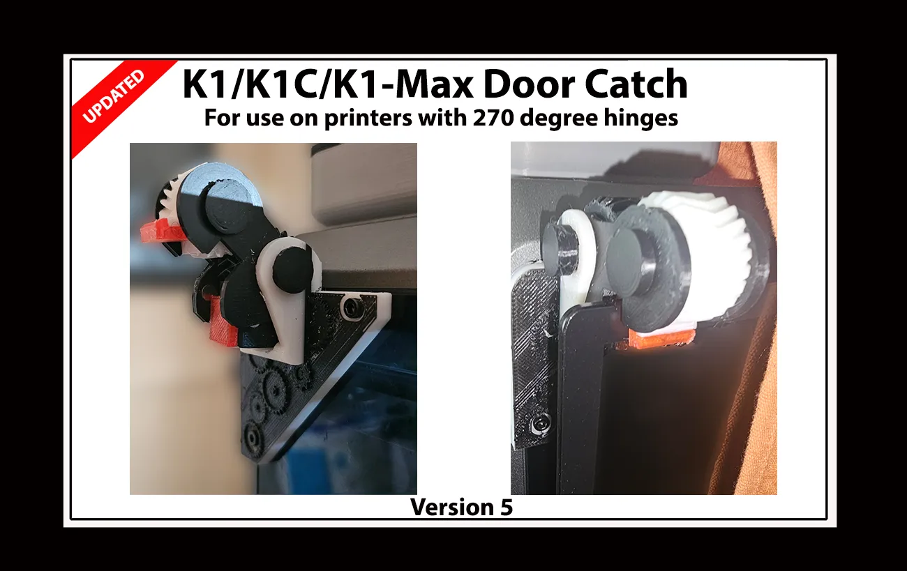
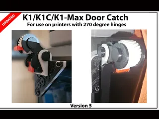
K1 Max / K1 / K1C. 'Penwald' Door catch. 270 Degree hinge glass door holder.


Opis
PDFIf You find this design useful, Please consider sharing a Make or leaving a comment. It's always good to see my efforts in use by others out there and it often inspires me to make improvements where I can. Without feedback I just draw a line under a design and move on to new projects.
-------------------------------------------------------------------------------------------------------------
Link added to easy print version 270 degree hinge set for the K1/K1C and K1 Max:- 270 Degree Hinges for K1/K1 MaxK1C. Easy print option, (Not print in place so more forgiving of printer tolerances).
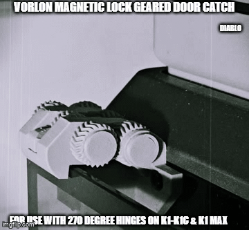
The ‘Vorlon’ door catch was the follow up to the Penwald. K1 Max/K1 /K1C. 'Vorlon' Door catch.
-------------------------------------------------------------------------------------------------------------
Note:- Late model K1 printers are coming from the factory using K1C frames. Identification is easy though. The gap between the screws at the corners of the frame sides on Original K1 and K1 max models is a little over 60mm. The K1C when released had only 20mm between the screws. Measure yours before you start. If you have a late model K1 and your screws are of the 20mm apart variant, you will need to follow the K1C instructions.
Sometimes you need a simple and potentially boring thing to accomplish a task. So here is a thing designed to do one of those simple boring things, but in the least boring and overly complicated way I could think of.
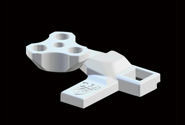
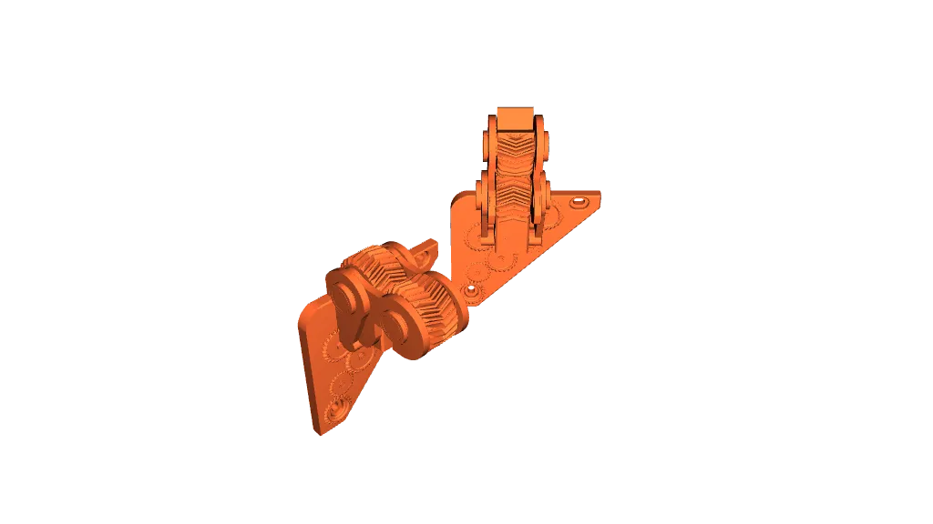
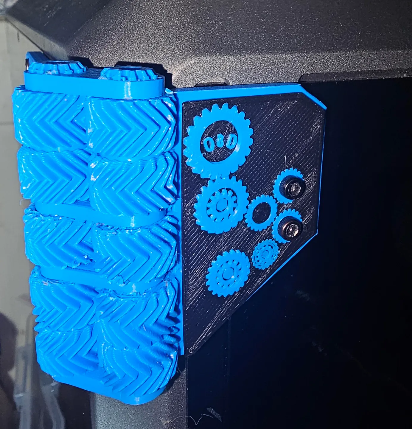
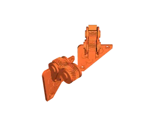
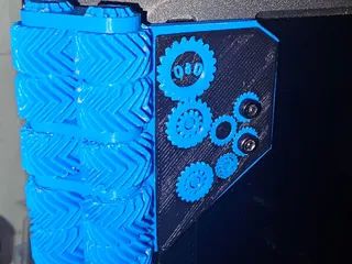
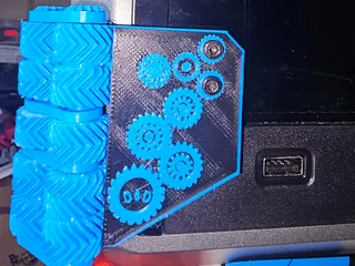
I originally designed this, the Penwald herringbone gear door catch, for my K1 Max that has 270 degree herringbone hinges fitted. I wanted a catch that kept the geared styling cues of the hinges but in a whole new ground up design. Since completing the ‘Penwald’ 2 gear set, I also completed the more complicated looking 'Vorlon' 6 gear catch that is now also available from my main Printables page.
Both the Penwald and Vorlon catches now support use on the K1 Max, K1, and the K1C.
Two mounts STL's are clearly marked as K1 Max and were (when created) solely designed for the max, they are the version I used on my own K1 Max before switching to the Vorlon. The other 2 mount plates are modified versions of the originals with additional screw holes that allow the catch to be used on all 3 current K series printers.
The catch itself is designed to use a couple of small TPU pads, one on the mounts bump stop, the other on the freewheel gear. These pads will safely grip the glass when the catch is in use. although the TPU is optional and not essential, it is still advisable to print the pads even if you do them in PLA as the gap between the grip surfaces will be too large without the pads being fitted.
I also designed it so that if the door is accidentally caught the catch will let go, reducing the risk of damage to either the printed parts or the glass door.
I originally set out to make it auto latch. Meaning opening the door fully would push the latch up and over the glass before holding the glass in place. For numerous reasons I ditched that idea and decided it was safer using a fully manual design so don't go shoving your door into the catch in the closed position expecting it to move out of the way. The auto latch idea added an element of risk to the glass that I didn't want. When not in use? you can fold the catch up and out of the way. When you need it again? fold it back down until it grips the glass.
If you have printed and fitted the pads? When the gear automatically rotates into its maximum travel position as it is closed, it will grip the glass as it clamps down removing any door movement.
--------------------------------
With the required magnets fitted it reliably holds the door securely in place even while printing and holds the door in place at the fully open 270 degree position.
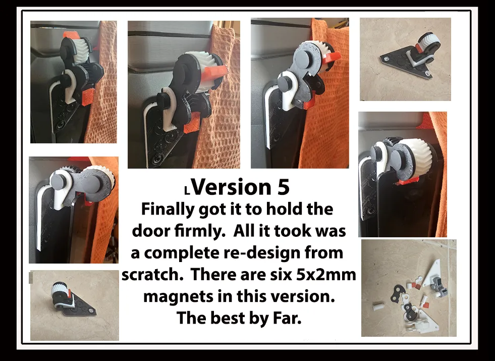
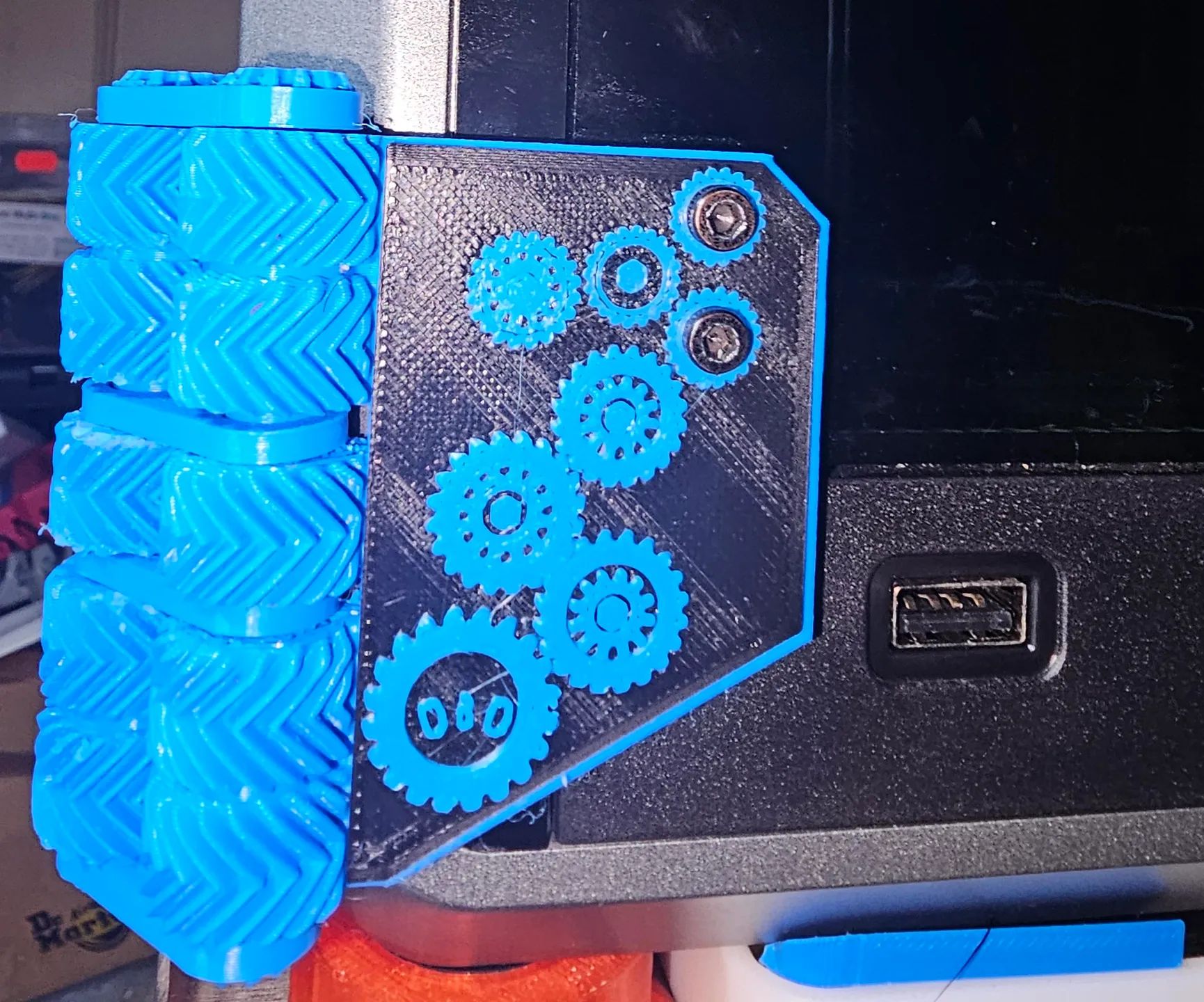
Although looking similar to my previous version of this design style, it is actually a complete redesign while keeping an almost identical aesthetic. It utilises Six 5x2mm magnets that effectively overcomes the forces in play that caused the unwanted door release issue in the previous version while printing.
The magnets are glued in place in their respective holes with superglue. There are four magnets in the captive gear segment (2 doubled up on left and right side) and 2 in the side plates (1 per plate).
The latch now forcefully snaps into position to hold the door. It has been designed to utilise both TPU pads on the faces that meet the glass. I provided an stl with 3 pads for the freewheel and 2 for the captive gear bump face. Pick a pad for both contact faces taking care not to block the gears movement when you attach the one on the moving gear.
If you don't print (or have) TPU? Print them in something else, even if it's PLA, as the gap will be over 5mm larger than the space taken by the glass without the pads and is not ideal. It will still work just fine, but the gap will be too wide and the lack of contact will allow the door to move about in that excess space. The pads were always part of the design and will create a more snug fit when in use.
----------------------------------------------------------------------------------------------
Assembly instructions.
K1 MAX version (K1 and K1c are different, info is shown below the K1 max instructions).
As already stated, this catch design requires Six 5x2mm magnets.
This explanation will sound long winded for what is actually a very simple assembly.
Note regarding the backplates :- ALL the mount plates have a 3mm hole to allow a screw to be fitted that will push up into the captive gear to remove any excess play. This screw hole is ONLY used if you use the V5a captive gear and find any play after fitting. The V5a version of the gear was added so that K1C owners can use this catch on their machines as once in place the captive gear blocks the mounting plate hole on those printers.
The original V5 backplates were designed solely for the K1 Max. Both are still here and marked K1 Max ONLY. Those using either of these 2 plates can fully assemble the catch before finally screwing the completed unit to the printer. This is absolutely the best option for K1 Max users.
For those using this option :- You ‘can’ use either version of the captive gear but the V5 was the one I originally designed for the max. This guide describes assembly with the original ‘V5 captive gear’ and is the preferred option for those using the K1 max only plates. I originally added a hole in the back of the gear with an associated hole through the mount plate to allow for screwing the gear in place. Once everything was fitted that screw did nothing but was originally added to remove any potential play in the captive gear. It wasn't needed in the end but deserved a mention in case you spot the hole and wonder why it is there.
Make sure the pins (spindles/axles) fit through their respective holes and move freely (I've printed multiple versions and occasionally had tight pins). Be extra careful with the mount ears as they may break easily if you are being heavy handed while the catch is not assembled. Sand the pins (or the inner bores of the ears and gears if you prefer) to get everything turning freely. The gears are meshed tight when fitted so there is wiggle room for sanding things down without unduly affecting the gear mesh. It is essential that the pins, side plates and the freewheel gear move easily.
Fit and glue the magnets,. two stacked on either side of the captive gear and one in each side arm (make sure you clear the holes so that they will be recessed or at least flush fitting). For maximum magnetic force (which we very much want) orient all of them in the same polarity direction. By that I mean, imagine the six magnets in a tube. All 6 of them should be attracted to each other. The PLA of your prints then effectively slots between them and around the ends. Doing them this way means the four magnets of the captive gear will effectively act like one big magnet giving you the best possible magnetic lock effect overall.
If you already printed the TPU pads (or pla for those without TPU) you ‘can’ glue the pads in place now. But remember that the side plates and freewheel gear need to be able to move so fit them centrally making sure they are not fouling, and not restricting movement. Personally, I did my pads after it was on the printer. Be extra careful if doing it this way as you don't want to accidentally glue a gear to a side plate.
Once you are happy things are moving freely enough, sandwich the captive gear between the two side plates and fit the plain pin to hold them to the mount. You can fit the end cap for that pin now as well (it shouldn't need glue, but if it does, make sure you only get glue on the cap and the pin head). Drop the side plates to the magnetic glass lock position, align and fit the freewheel gear securing it to the side plates with the other pin, and attach the end cap when it is aligned correctly. The glass grip aperture should be almost square. Test the catch through its available movement range to make sure everything moves freely.
That's it for K1 Max assembly and you can fit the completed catch to the printer now.
-----------------------------------------------------------------------------------------------------------
K! and K1C instructions.
Because Creality use different positions for the side screws on each printer model release, I amended the mounting plates to be suitable for fitting all three current K series printers (K1/K1C/K1 -Max). One of the new holes required for the K1/K1c fell in a bad place on the Penwald bracket and caused me a huge redesign headache, but the end result was that the catch can now also be used on the K1 and K1c. It did however require a change to the overall original design and a slightly different way of assembly for the catch to allow it to be used with the K1/K1C.
K1C users NEED the V5a Captive gear and the more generic K1/K1C/K1-Max mounting plate (These plates have four mounting hole options instead of 2). One of those holes falls directly in line with the captive gear which created the need for the modified V5a captive gear and the different fitting procedure.
Pre fit everything to make sure all is well and the pins/spindles and mechanism all move freely as per the description in the K1 max instructions above.
In order to fit the catch to the printer, K1/K1c owners will obviously need access to the mounting plate hole that is hidden behind the captive gear when the catch is fully assembled. Remove the spindle/pin from the captive gear (releasing the captive gear, side plates and freewheel gear from the mounting plate) then fit the mounting plate to the printer. I made the offending hole in the mount deeper so the screw will not foul on the captive gear when it is refitted to the plate.
Once the plate is attached you can reassemble the catch and fit the end cap which completes the build.
Printing instructions. I suggest low layer heights and high quality for the gears themselves. The rest of the parts are up to you. I did it all at high quality settings once I was happy with the design.
- Print the Mount plate flat with supports
- Print the side plates flat with magnet holes facing up- no support
- Print the gears flat. Captive gear needs support for the holes
- Print pins upright, caps with opening facing up-no supports
- Print the TPU pads flat
- I added a pair of hole plugs to fill the screw holes you don't use when attaching the unit to the printer.
Please let me know how it went for you. Especially K1C users as the design changes to allow for their printers were all done after finalising the K1 Max version.
The Six gear ‘Vorlon’ catch is also now available here for those who want a different option:- K1 Max, K1 and K1C. Door catch for 270 Degree hinge users. Updated with 2nd gear set option. by Diablo | Download free STL model | Printables.com
Thanks go to Mordiev for his help with my bracket hole spacing.
------------------------------------------------------
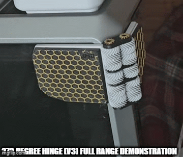
The Gif video shows my original proof of concept design. I just wanted to see if it would work as I intended, but I never got around to filming the Final version. It does still show how the grip face rotates into position though. The gap when closed to hold the glass is now near zero unlike the chasm in the version shown in the video
Tagi
Pochodzenie modelu
Autor oznaczył ten model jako własne oryginalne dzieło.