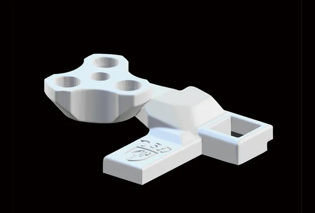
K1 Max/K1 /K1C. 'Vorlon' Door catch. For use on printers with 270 degree hinges fitted

Description
PDFIf You find this design useful, Please consider sharing a Make or leaving a comment. It's always good to see my efforts in use by others out there and it often inspires me to make improvements where I can. Without feedback I just draw a line under a design and move on to new projects.
-------------------------------------------------------------------------------------------------------------
Link added to easy print version 270 degree hinge set for the K1/K1C and K1 Max:- 270 Degree Hinges for K1 /K1C/K1 Max. Easy print option, (Not print in place so more forgiving of printer tolerances).
This is my other catch design for use with the 270 degree hinges K1 Max / K1 / K1C Door ‘Penwald’ catch for use with 270 degree hinges
Update may 2024:- Issue with the B gearset maglock rectified. An older reversed and abandoned gear design had crept into the fileset during an update.
Update:- I've added the option to use a different set of gears (Gearset B). The B set give the catch a different aesthetic from that of the initial gears I used in this catch design.
-------------------------------------------------------------------------------------------------------------
Note:- Late model K1 printers are coming from the factory using K1C frames. Identification is easy though. The gap between the screws at the corners of the frame sides on Original K1 and K1 max models is a little over 60mm. The K1C when released had only 20mm between the screws. Measure yours before you start. If you have a late model K1 and your screws are of the 20mm apart variant, you will need to follow the K1C instructions.
THERE IS A LOT OF TEXT HERE AS I HAVE GONE INTO WAY TOO MUCH DETAIL THAN IS NEEDED.
The TLDR is :- This is very easy to put together. Look at the pics, follow the pics, put it together. The only important parts are that the 3 captive gears are fitted correctly and that the 2 pins that hold the mechanism together both move freely once fitted.
The following is the long description of the build
Layout the parts. Select the mounting plate and the 3 captive gears (noting the central gear mounting point is different to the outer gears). Run the long pin through an outer loop of the mounting plate and one of the correctly aligned outer captive gears. Align the main catch (hook) and slide the pin further in to keep the catch in place. add the central captive gear and slide the pin all the way through the hook portion before adding the last captive gear and pushing the pin fully home before adding the end cap. Make sure the catch moves freely at this stage.
Now hold an outer gear in alignment with the catch hole and slide the smaller pin in through so it locates in the main catch. Add the maglock centre gear, slide the pin through further, and finally add the last gear before pushing the pin fully home and adding the locking cap to hold everything together.
All the other info below is for those that want to be more fully informed and like to know everything they can know before assembly.
Note:- Before assembly, check the photos of the completed gears to ensure correct orientation of the gears. After over 70 downloads somebody discovered they could fit the Central captive gear of the B gearset in the wrong orientation (which is obviously not going to work as it was intended). For the B gearset, all 3 captive gears share the same directional alignment. As a simple description:- with the catch closed while looking from above and using the teeth as directional arrows, the two rows of gears on the completed catch will all need to be pointing towards each other. The A set is different,, with only the centre pair point towards each other and the outer gears pointing away from each other.
-------------------------------------------------------------------------------------------------------------
After the nightmare making the first 270 hinge latch you would think I would have given up. But nope, with what I learned there I came back at it from a different perspective. The previous geared latch was a 2 gear design. This is a 6 gear variant.
I added a demo STL file to the set just for the Printables 3d viewer. It's just the parts aligned roughly to show it in 3d. Any artefacts, issues, quirks, misaligned gears, or just wonky angles, is solely because that file is just a quick throw together of the parts to show the basic appearance in a 3d view.
The Vorlon latch mounting plate has screw holes to allow fitting to all 3 current Creality K series printers. The catch uses three 5x2mm magnets in it's design to help lock the catch down when it is in use. I highly suggest you get the required magnets as it was an integral part of the design and is there for a legitimate reason. Without them the catch holds the door far too lightly for my thinking. Although you can perhaps get away without using the magnets, I would seriously have my doubts about the catch holding the door firmly enough when actually printing. That holding issue while printing was something I had quickly discovered with the 2 gear variant and had necessitated a complete overhaul of the Penwald design to correct it, so this time I came at it with a plan for the magnetic lock connection already in mind.
The 3 captive gears at the rear (nearest the mount plate) have been designed to be a structural component once held in place by the long pin and add support to the minimalist ears of the mounting plate. Keeping the mounting holes free in the plate for K1C users to also be able to use the catch resulted in minimising the widths of the spindle mounts on the mounting plate for the captive gears. Doing it this way prevented ruining the aesthetics of the original design.
The 4 mount ‘ears’ on the mounting plate are delicate when the unit is in it's component form but once the gears are fitted they are well supported by the captive gears and the unit is considerably more robust than it might initially appear when first handling the printed part.
The 3 rear captive gears have a small cutout where they meet the mounting plate to prevent them moving once the long pin has been slid into place. The pins primary purpose is to hold those captive gears while also allowing the catch mechanism to freely rotate. The V shaped notch in the captive gears is important and is designed to sit against the front corner of the top of the mounting plate. The horizontal part of the notch rests on the frame and the vertical part pushes against the face of the mounting plate so that when the pin is fitted the Captive gears cannot move. If they are not seated correctly you could also potentially jam up the threads as the available teeth of the captive gear are far less than the freewheel gears with a fair chunk of the gear being effectively embedded within the frame of the Mount. Simply put, no movement in the captive gears is what was intended.
Although the original version of the vorlon started with 3 identical captive gears, for this new revision, one of those 3 captive gears is different to the other 2 . For the outer two gears the slope sits vertically and interfaces with the front of the mounting plate, with the stubby rectangular lug resting on top of the plate. The middle captive gear started life the same as the outer pair and consequently retains that rectangular lug, the important difference being that the vertical slope portion had to be cut back to fit correctly against the new design of door stop.
Once the pin is fed through the tabs and the ‘correctly aligned’ captive gears, they will be firmly locked in place and unable to move. If in doubt (and just in case the above description wasn't as easy to understand as I tried to explain it)? have a look at the 3d view in the Printables photos as it shows the captive gears lug/cutout fitment more clearly.
During assembly, make sure the pin moves freely. I have printed the full set multiple times and only one had tight pins that needed some sanding to fit better. I would rather this than resize the pin and have the gears too loose. That said, I did also sand the pins on one test print that was already working fine, But after getting the tight pin version feeling so smooth, I opted to smooth the pins in my other test prints as well.
The Freewheel gears (which are not actually freewheeling, I just found it easier to name them freewheel as those 3 can actually rotate) consist of 2 identical gears and one gear modified to act as the magnet lock. The 2 regular gears fit to the outer mount points and obviously mesh to the outer captive gears. The Middle modified gear also meshes to the other gear but it has the added protrusion for the maglock capability. Make sure you clear any and all support material from these holes before fitting the magnets as I kept the depth and width tolerances tight (Do I need to emphasise that you check you are fitting magnets in the same polarity where they meet?).
Drop the latch into the closed position before fitting the 3 freewheel gears. The gears are set to mesh as near near perfectly I could get them when the latch is closed. If you fit the gears with the latch at any other position you can end up with the latch sitting at an angle rather than coming to rest on the glass stop as it was designed to do (that effect is visible on a couple of the photos of the B gear set where I was deciding myself if I preferred A or B).. Having the magnets fitted and putting the centre maglock gear in place during assembly can help align things better here. As with the longer rear pin, fitment of the shorter front pin holds the rotating gears in place and holds them mated to the captive gears. The end caps provided should not need glue and and are sized to be pressed on tightly Take care to press both sides together or hold the pin while adding the caps to prevent snapping the mounting plate ears with too much sideways pressure against the mount ears. I have my end caps facing the back of the printer solely as they are hard to distinguish from the pin when fitted and I took mine apart a few times when checking things during the test stage so it was worth me knowing which ends were caps. Obviously that doesn't matter if you are happy with everything and don't intend removing it.
In operation, lifting the catch causes the modified central free gear to break the magnetic connection as it is forced to rotate. The gear design causes the magnet piece to rotate faster than the actual glass catch as you rotate the mechanism upwards, Similarly when closing the catch the magnets are reintroduced to each other as the locking gear automatically rotates back into the closed locking position giving additional grip to keep the catch in place and hold the door effectively. There is more than enough force to hold the door while printing without any hint of an unwanted door release. It was, I thought, a more elegant solution than I initially designed on the Penwald ‘2 gear’ version.
This design works perfectly as intended if the magnets are used. Although you may get away with not using magnets, I am unsure how well it would perform without them while printing. Any lateral movements of the door that make contact with the latch cause the gears to convert that movement into an upwards motion of the latch. Without the magnets I suspect the catch could let go of the door while printing. The magnets more than compensate to prevent that rotation/lift effect from happening.
For mine, I added a small square of TPU to act as a buffer when the door meets the catch stop. It was sized specifically to remove any space between the actual catch, the glass, and the protruding door stop of the mounting plate when the catch is in use.
There is an stl for two equal depth pads. One is square, the other is elongated. You can choose the one you prefer the look of. The Vorlon catch only requires ONE of those pads fitting to the bump stop of the mounting plate for correct tolerances. If you don't have, or use TPU? Print the pads in pla (or whatever filament you used for the rest of the print) and fit the one of your choice to remove the excess space that not having a pad would create. Note:- All the space dimensions were done to correlate with Mordiev's hinge set. If you are using a different design of hinges then it is possible you personally may benefit from not using the pads as your hinges could potentially alter the angle where the glass meets the catch and change the designed gap tolerances as a result. For Mordiev hinge users, the addition of the pad will result in a correct fit.
I added a pair of hole covers (in a single stl). These will fill the two extra holes that you don't use when fitting the catch to the printer. I hated the look of the two unused holes enough to come back and make the plugs. Unlike in the pictures, the plugs themselves are hardly visible when the catch is actually on the printer and look far better than 2 unused gaping holes that do nothing. If you are using Mordiev's hinges then these plugs will also fit his hinge plates.
In relation to the 3d image that Printables shows along with the pictures on this page. You might also spot the letters A and B on the rear of the plate. Ignore them, they mean nothing in the final design (and are not seen when the plate is fitted), they were just reference marks that I used during the original design stages that got overlooked for removal once the design was completed.
Tags
Model origin
The author marked this model as their own original creation.