K1/K1C Exhaust Upgrade

Description
PDFWARNING:
***DO NOT ATTEMPT TO POWER THE 24V/0.5A 120x120x32mm BLOWER FAN WITH THE ORIGINAL CABLE PLUGGED INTO THE MOTHERBOARD***
Introduction
This upgrade allows you to print PLA with the door closed and the top panel on with a vented riser (I recommend picking one of the options from @RAPHLEO). This “sealed” configuration reduces the total noise output by blocking most of the noise generated by the toolhead fan. Additionally, it replaces the stock 6000rpm 40mm fan which lacks airflow and static pressure. This upgrade can be combined with any other externally mounted carbon filters or exhaust hoses.
Design
Optimized Geometry
The geometry is designed to reduce backpressure, resistance, and noise (turbulence). CFD simulations show a (mostly) concentrated flow pattern that ejects the hot air far from the printer. The airflow can be noticed up to 4 meters away from the exhaust.
Zero Tolerance Fitment
All parts are designed to near zero tolerances to ensure that fitment is tight and requires no additional parts. You may optionally choose to use CA (super) glue to permanently secure the duct to the adapter.
Reverse-Convection Airflow
Designed with vented risers in mind, this upgrade pulls cool air over the toolhead (including the extruder) which eliminates heat-induced extruder jams. The hot air is forcibly pulled downwards and exhausted out of the rear.
Negative-Pressure Chamber
When printing in a fully sealed configuration (with riser vents closed), the negative pressure environment ensures that no harmful fumes escape into your room. Connect a hose to the rear and vent the fumes out of a window. Don't forget to limit the fan speed to ensure that the chamber stays at an optimal temperature for ABS/ASA/Nylon/etc.
Integrated Fan Clip
A small clip is integrated into the duct to help manage the fan cable.
BOM
Cooling Assembly
1x 120mmx120mmx32mm 24V/0.5A (12W) Fan (or equivalent 12V externally powered fan)
4x Screws used to secure the original fan
1x Toolless Fan mount
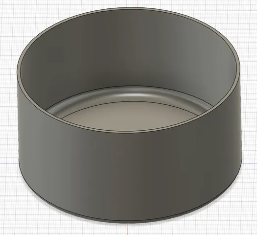
1x Duct
1x 40mm Adapter
2x Strips of 1mm thick mounting tape/foam
Power Delivery
1x Optocoupler-MOSFET board of your choice
18-22 AWG Wire
2-pin JST-XH 2.54 Connectors + Pins + Crimping Tool
Filament Recommendations
- PETG/CF-PETG (For exclusively PLA printing)
- ABS/ASA or their CF/GF counterparts
DO NOT USE PLA. The material softens causing the toolless fan mount to weaken/deform and no longer tightly grip the fan. PETG is suitable if you are printing PLA exclusively but will also fail if you are printing high temp filaments at higher chamber temperatures.
Installation Instructions
Toolless Fan Mount
Apply two strips of 1mm thick foam mounting tape or clear acrylic tape to the mount. Install against the back panel of the printer ensuring that it sits against the bottom panel and the z screw shield. Press firmly to ensure proper adhesion.
120x120x32mm Fan
Orient the fan with hole pointed in the vertical direction. Align the left edge of the fan with le left edge of the mount about ¾ inch above the bottom. Then press the right side of the fan into place so that the entire back of the fan contacts the mount. Press downwards to slide and lock the fan into place. Plug the fan cable into the original fan connector AFTER completing the modifications below.
40mm Adapter + Duct
Slide the duct into the adapter. It should be a snug fit with no gaps. If a gap appears, your tolerances are off and you will need to adjust the corners of the duck with a deburring tool and/or utility knife. Use caution if adjustment is needed. You may optionally decide to secure the two pieces together permanently with CA glue.
Place the adapter into the exhaust slot. The standoff should align perfectly with no wiggle room. While placing pressure on the adapter, screw in from the back in a diagonal pattern. DO NOT allow the screw to push the adapter away from the rear. Doing so will result in an improper fit and ruin the alignment.
Wiring Schematic
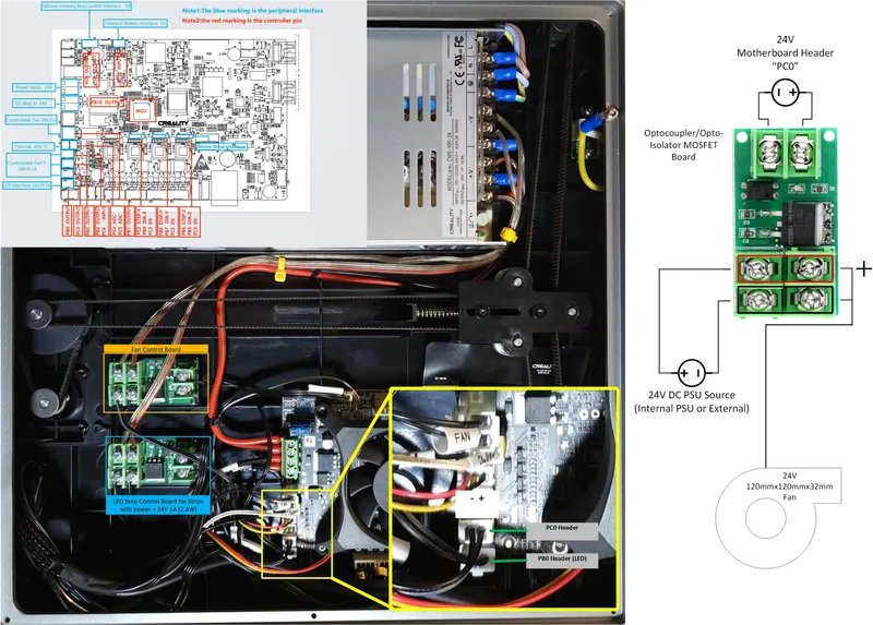
NOTES:
A higher resolution PDF is included in the download files.
Depending on the Opto-MOSFET board you are using, the polarity may be different. Adjust your wiring accordingly. Ensure you have a multimeter on hand to validate.
I would not recommend messing with power supplies and wiring if you do not know what you are doing. Use Caution.
Customization and Other Requirements [WIP]
Fan control requires a rooted printer in order to set PWM frequency to maintain speed control.
Tags
Model origin
The author marked this model as their own original creation.