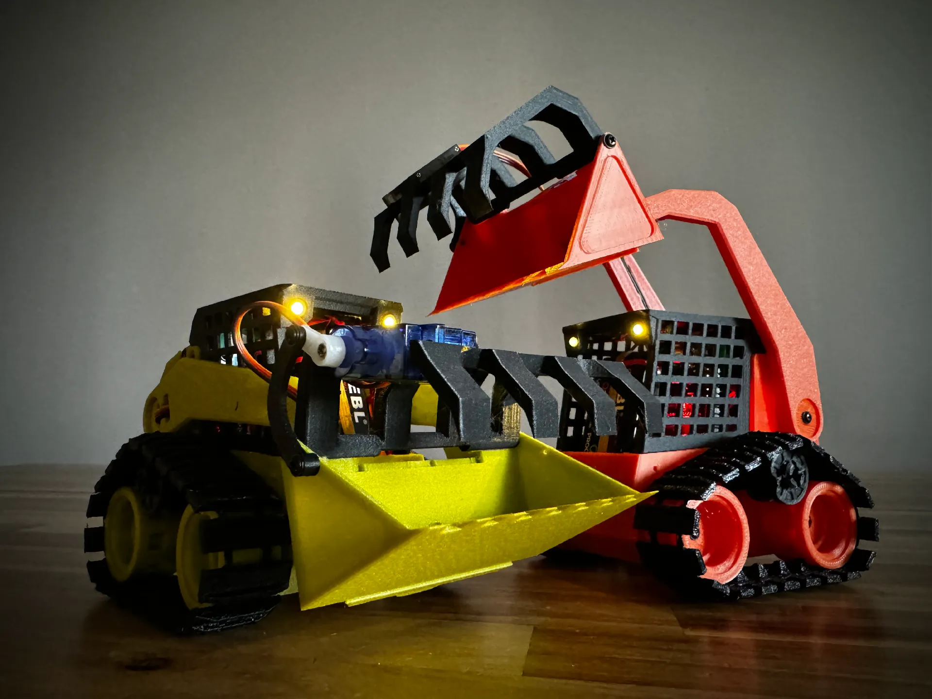
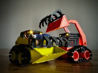
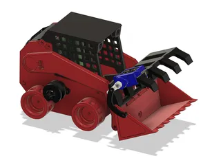
3D Printed RC SkidSteer V4.0
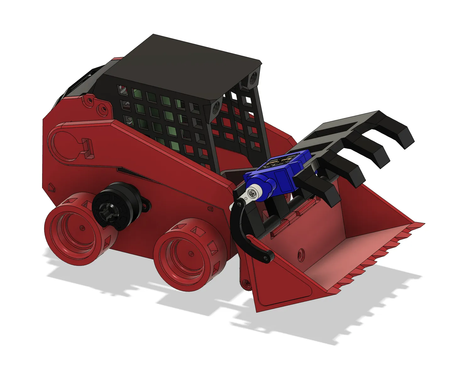


Description
PDFSummary
I started with just a few minor adjustments to improve printability and make it work with PCB I already had. But it quickly snowballed into a lot of different improvements for printability, bug fixes in firmware, optimising BOM and more. So I decided to call it V4.0.
Firmware improvements
Fixed some minor bugs and removed blocking delays to make operation smoother. Now it also has proportional control for both bucket arm and movement allowing for way more precision. Migrated to bluepad32 library making it compatible with a large variety of gaming controllers such as PS4, PS5, xbox, google stadia and more, it also makes pairing process much smoother, just put your controller into pairing mode and turn on the skid steer, once it finds the controller it will wiggle its wheels a few times and ready to go.
New firmware is available here https://github.com/Le0Michine/MiniSkidi-V4/blob/main/MiniSkidi_4.0/MiniSkidi_4.0.ino
Pairing sequence
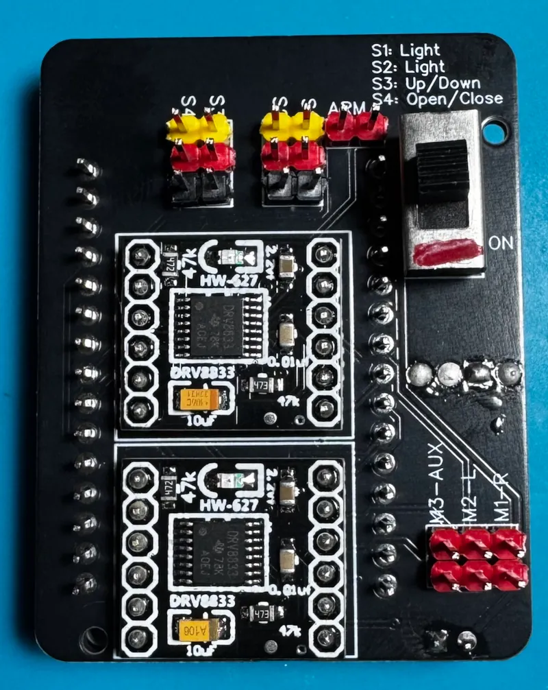
PCB V2 fixed
Attached gerber file for a new PCB which includes fixes required for better work. This eliminates the need for manual alterations of the original PCB. Same components are used for assembly except for motor connectors, instead of screw wire terminals dupont headers are used, they offer plenty of current capacity and are easier to use during assembly. Each connection is labeled.
PCB V2 support
Gerber file can be found in “Other Files” section as well as in the firmware repository here https://github.com/Le0Michine/MiniSkidi-V4.
Since only PCB V2 was made available for free download I made main housing to fit it. Unfortunately, that PCB version has a couple problems:
- it routes motors power through step down converter limiting the speed significantly
- it routes all 3 extra aux channels to the esp32 pins which aren't actually usable as outputs which means lights can't be controlled
Both of these issues can be easily corrected and because I ordered the board before checking it that's what I had to do.
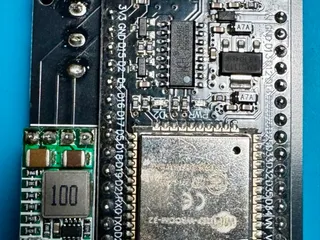
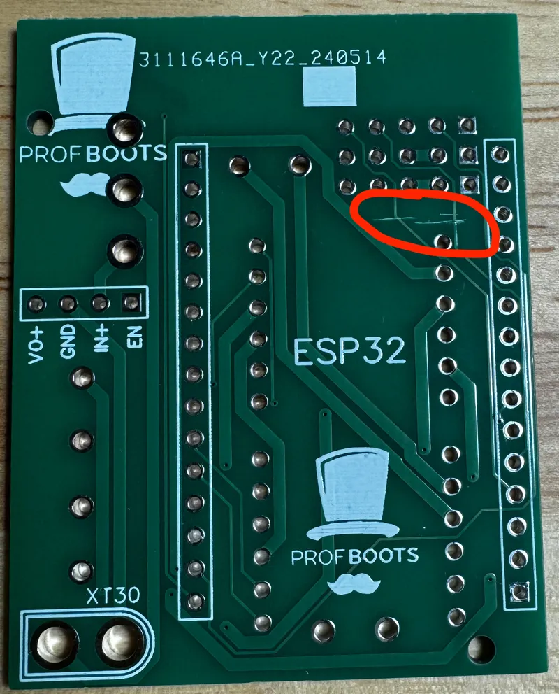
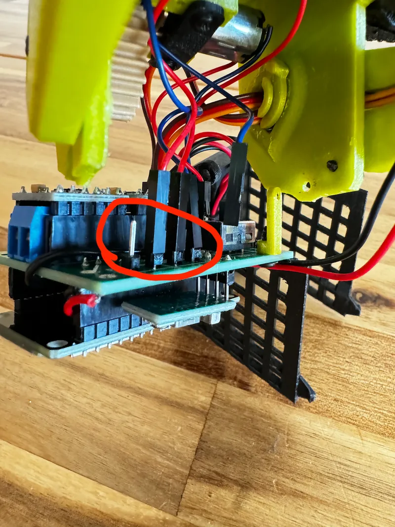
Power rerouting
To reroute power from the battery directly to the N12 motors you will need to cut the existing power trace with exacto knife as shown on the picture:
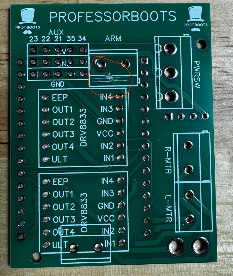
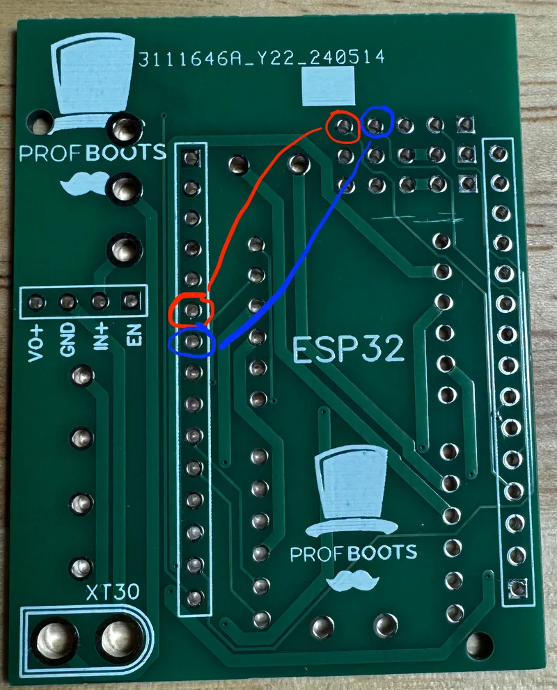
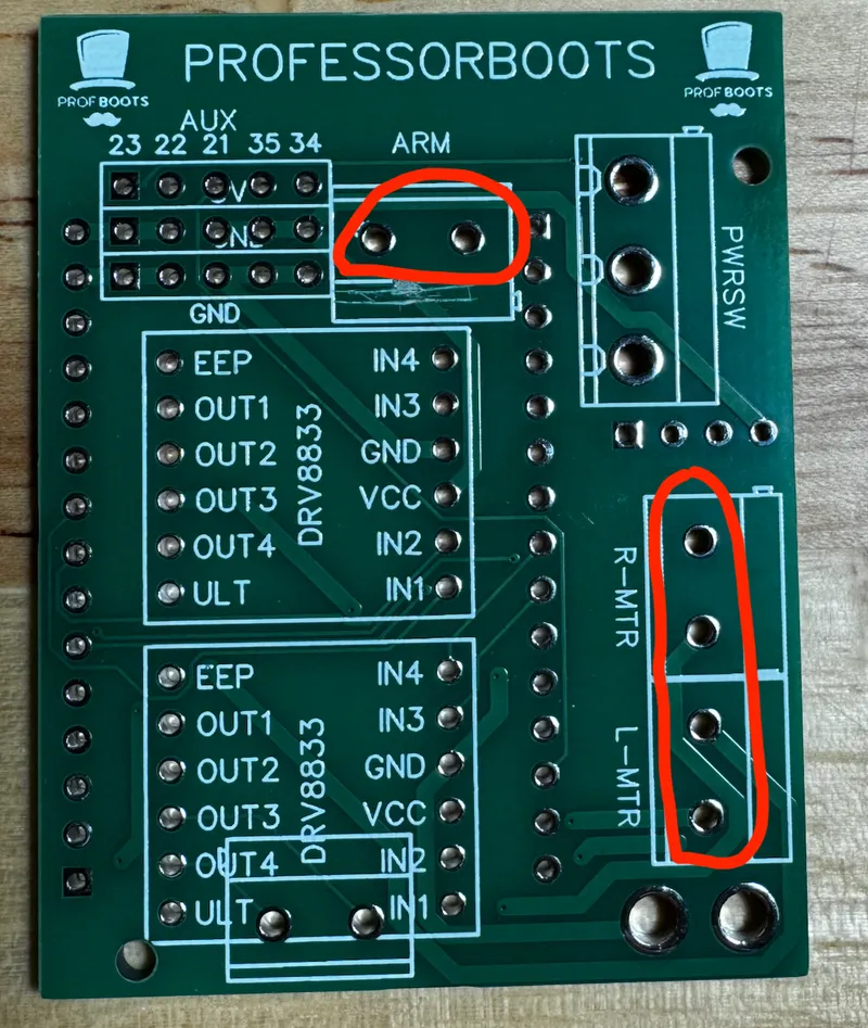
And then after soldering all the headers connect the highlighted spots with a wire
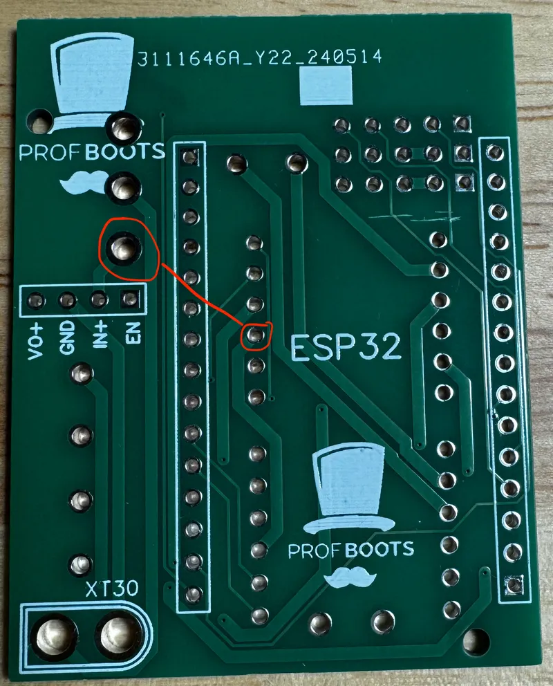
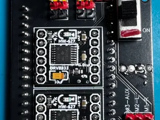
To connect the aux channels we will use pins 16 and 17 which aren't connected to anything (new firmware is written assuming lights will be attached to those pins). To start we need to cut the existing traces as shown below
Then we will need to connect the outputs to pins 16 and 17 as highlighted below. Make sure to do this after all the headers are soldered to the board
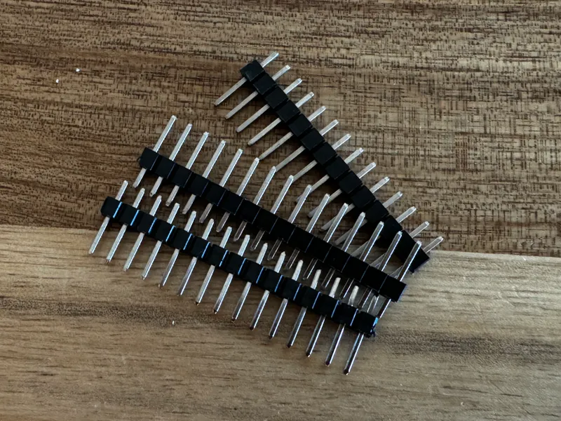
Another recommendation is to use dupont headers instead of screw terminals. They are more common and you would need some for servo connectors anyway. Also it will make swapping motor direction when assembling easier. You can use wire cutters to cut off single connector from the rails for each of the 3 motors.
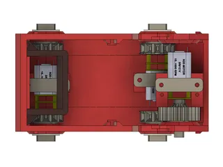
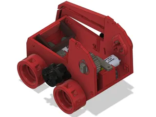
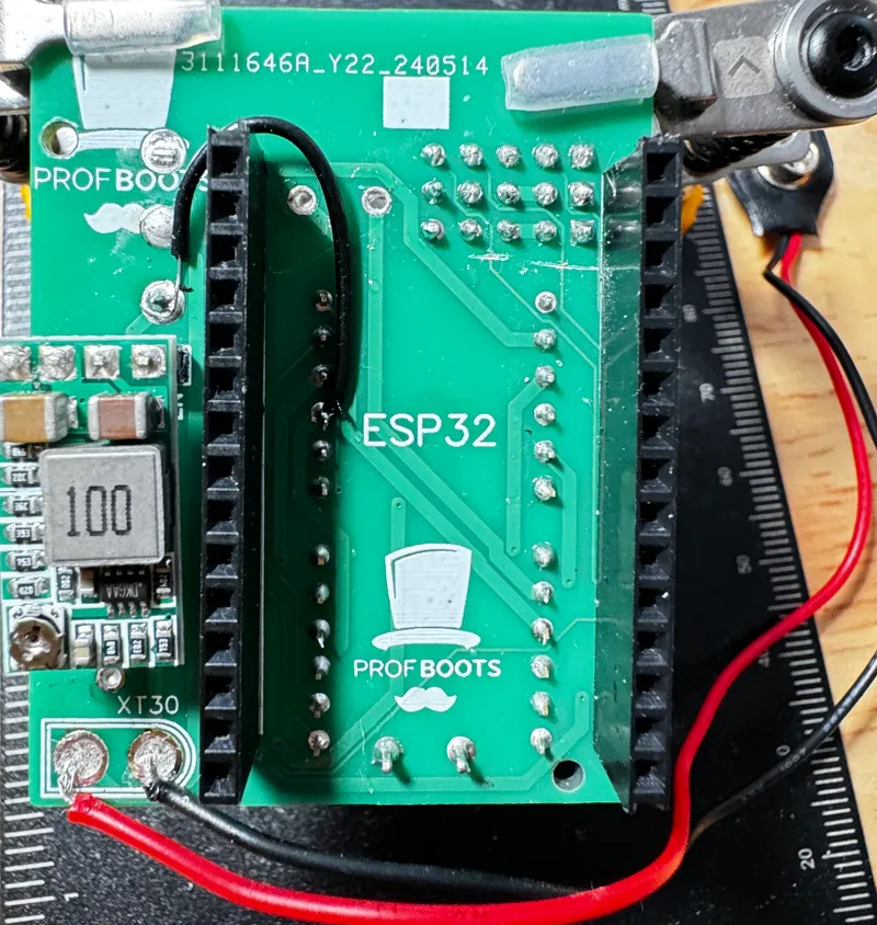
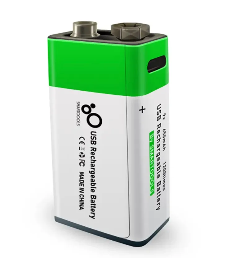
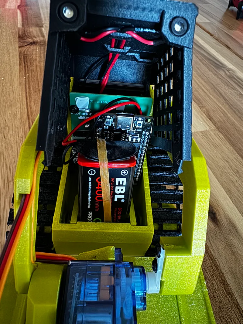
Batteries
Because recommended fenix batteries weren't available for me I opted in for 9V rechargeable batteries which are actually seem to be just two cell standard li ion batteries (they don't reach 9V even fully charged), they also have nice usb ports for charging and have simple shape which allows for easy installation, all of that makes them fit very well for the project. Picture below is just for the reference.
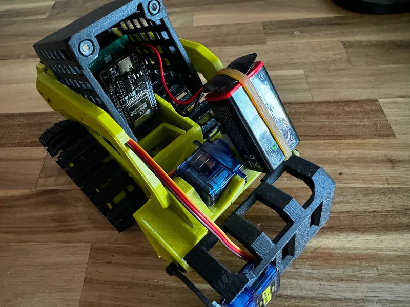
The connector can be easily soldered to the XT30 mounting holes, as can be seen on one of the pictures above. Battery slides into the holder at the front of the vehicle as shown on the pictures below. I use rubber band to kip it from moving or falling out when the car flips over.
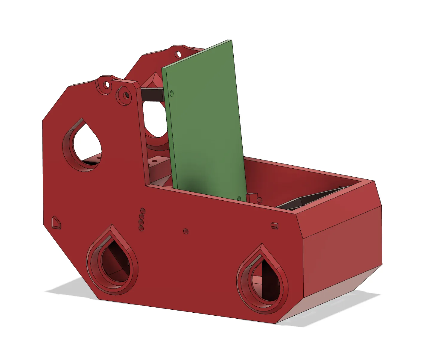
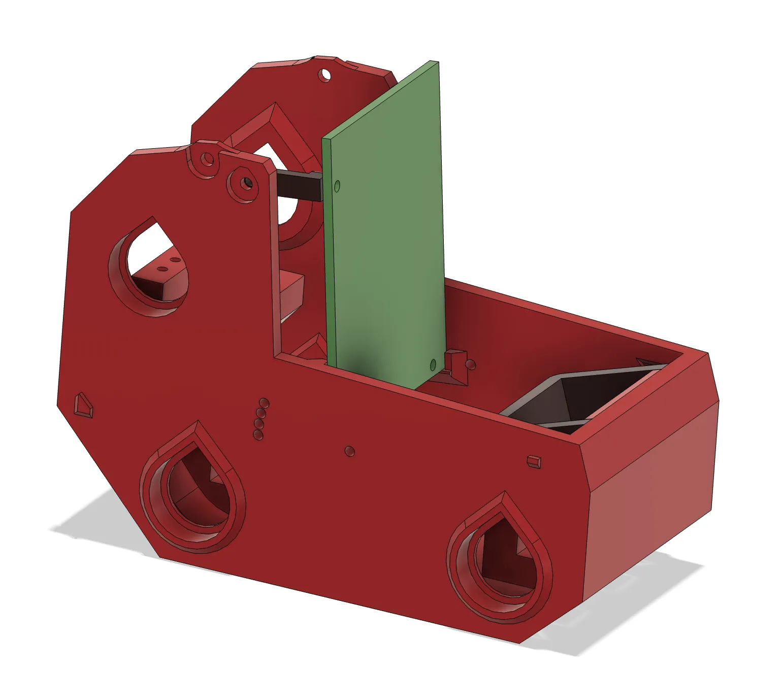
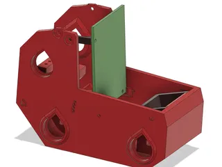
PCB installation
This step is done last, after everything else is assembled. Bottom part of the PCB would slide into lips on the sides of the housing while top is secured with a screw on one side using a small bracket.

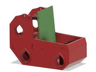
Printability improvements
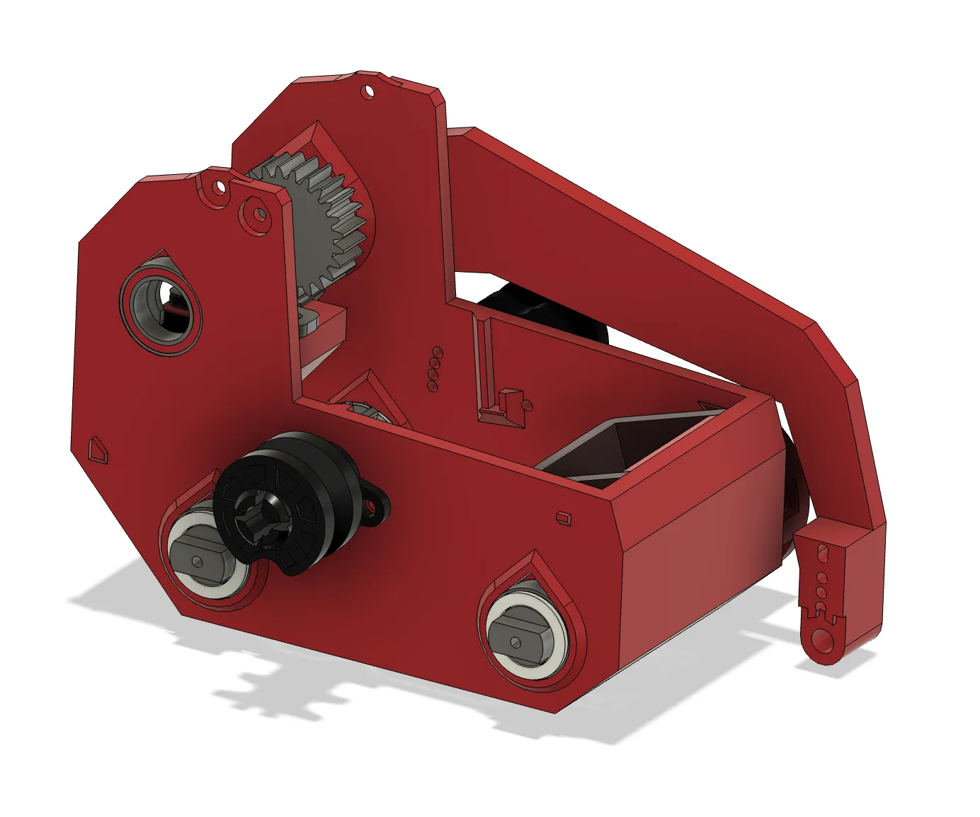
Most of the parts have been adjusted for better printability by removing overhangs, sections which otherwise would print in thin air. Main housing can now fit V2 PCB (also included). Also removed some small gaps where they weren't needed simplifying internal structure. Gears are thickened to make them stronger so there is no need for extra reduction. Thanks to firmware changes bucket arm now can move slower or faster depending on user input and the limiting factor is vehicle balance rather than lack of power. Bearings for arm axis are especially helpful as they prevent early gears skipping and make overall operation much smoother.
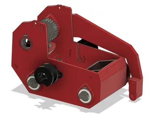
Bearings and screws
This version requires 6 common bearings 10x15x4 which make operation much smoother. Most of screw holes were modified to fit the same screw size, so now you can assemble it using just 2x8mm screws with large cap and a single 2x8mm screw with small cap for attaching right arm to the bucket. Or 2x8mm machine screws can be used all the way throughout.
Bearings are press fitted into the body so it might take some time to get them in, however, after that everything works very well. Make sure to put in driving shafts and motors before installing bearings as due to very limited space it won't be possible to assemble after bearings are installed.
Drive shafts still can be fitted with a belt, however, tracks just work much better than wheels so I would recommend just use tracks.
BOM (Not printable parts)
Screws
- x31 of 2x8mm with wide cap
- x1 of 2x8 with narrow cap to fit the recess in right arm for bucket mounting
All screws can be replaced with 2x8mm machine screws, they tend to be stronger so less chance of snapping screw head.
Electronics
- x2 3mm leds
- x2 3mm led plastic sockets
- x2 9g servo motors (can be either metal or plastic gears)
- x1 ESP32 WROOM-32 Development Board
- x1 switch SS12D10 (4.7mm pitch)
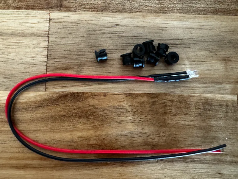
- x1 9V battery clip with wires
- x1 DC-DC Buck Converter
- x3 N20 motors 12v 100RPM
- x2 DRV8833 motor driver board
More details about individual parts below
Lighting
x2 3mm leds
x2 3mm led sockets
Servo motors
x2 of 9g servo motors, both metal or plastic gears work great
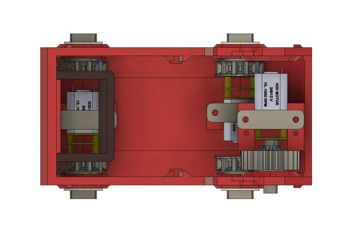
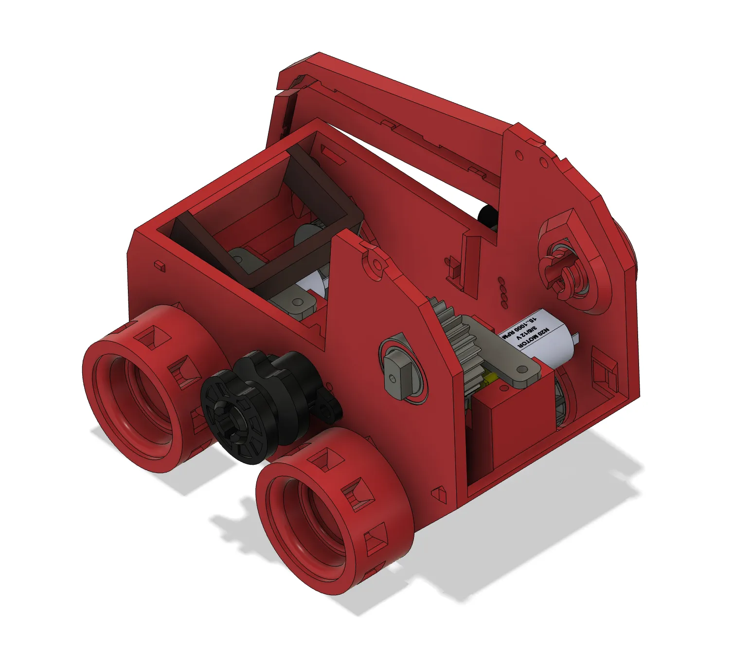
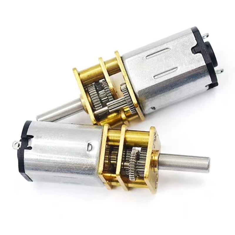
N20 motors
x3 of N20 motors, 12V 100RPM. 2 of them are needed for driving tracks, can be higher RPM for faster movement, just make sure they are the same. For the arm higher RPM isn't recommended.
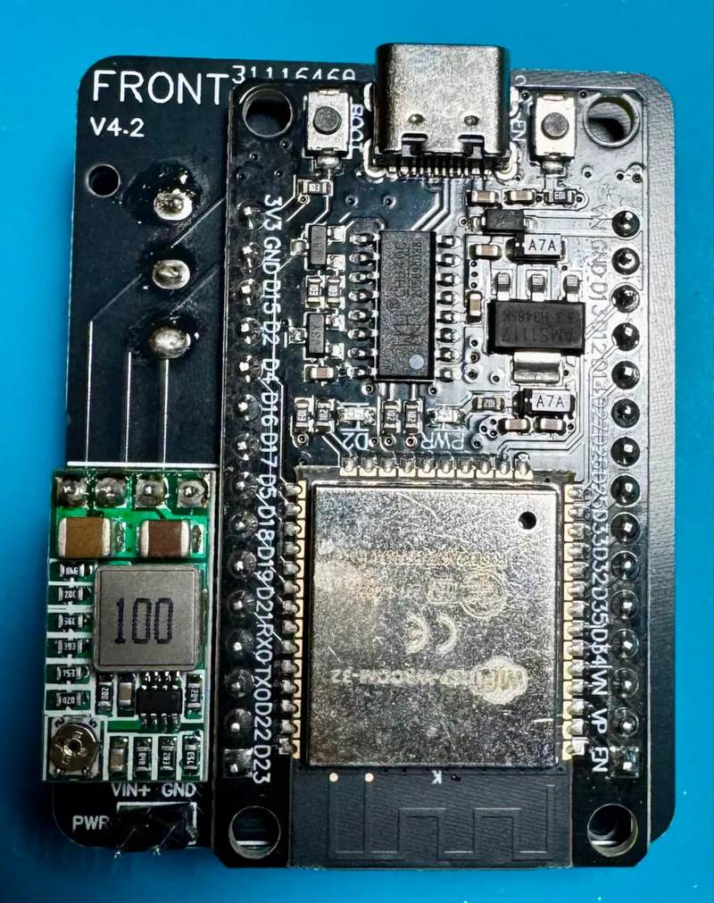
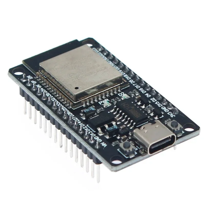
ESP32 WROOM-32 Development Board
They are available with USB-C connector or micro USB, whatever version is more convenient for you will work. Make sure it has 30 pins (15 on either side). It has bluetooth which will be used for pairing with gaming controller.
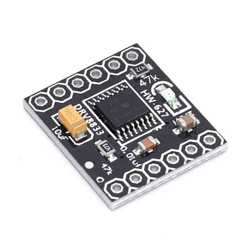
DRV8833 Motor Drive Module Board
Will need 2 of these
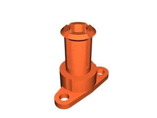
Step down converter
1 of these will be required, make sure to get one with 4 pins on one side as on the picture. Other would work too but will need some wires to fit it onto the board.

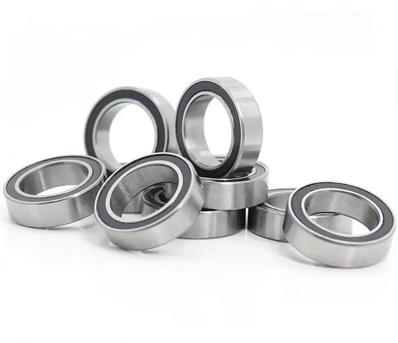
6700 Bearings (10x15x4mm)
6 is required for the whole build
Model origin
The author remixed this model.

Differences of the remix compared to the original
Summary
I started with just a few minor adjustments to improve printability and make it work with PCB I already had. But it quickly snowballed into a lot of different improvements for printability, bug fixes in firmware, optimising BOM and more. So I decided to call it V4.0. More details about improvements in the description.