Cubey 2 Puzzle Box

Description
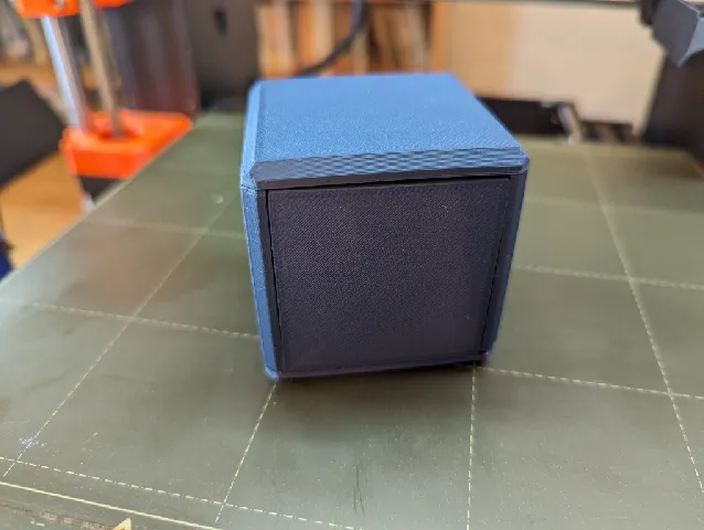
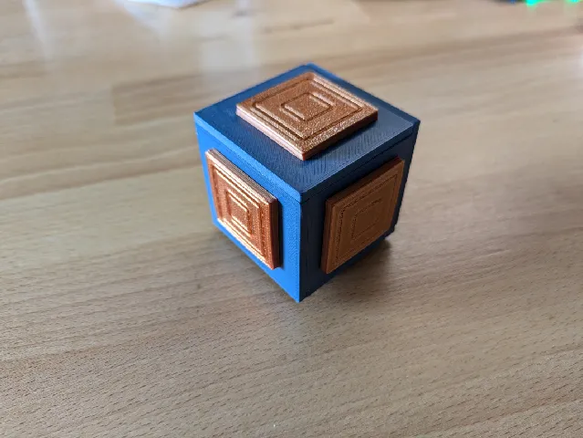
PDFA small cube with six apparently identical sides. By sliding the decorated panels one by one, you can lift the top off the box. It is a successor to Cubey (https://www.printables.com/model/888900-cubey-puzzle-box) and requires more moves.
The box was adapted from Cubey 2 by Bruce Viney. The original copyright notice on the plans for Cubey 2 says These plans are free. If you sell or give away this puzzle, please mention where the plans came from. The current site for Bruce Viney's plans is https://brucevineywoodenpuzzles.wordpress.com/. I confirmed it is OK to publish this with the site's owner. The dimensions and some of the geometry is a little different from the original.
Instructions
It's quite hard to assemble Cubey 2. Expect to have to put it together and take it apart a few times until you have everything working smoothly.
Start by printing the six panels which form the sides of the cube. They are connected to small tabs which fit into recesses. I recommend filing the recesses out a little. Ideally the tabs should fit snugly but you should still be able to take the box apart. The tabs break off very easily so when attaching or removing the panels do it gently and in the direction of the tabs. When you have added all the other parts, you can glue the panels together if you choose. Don't glue the top down!
Each panel has lettering on it: L(left), R(right), F(front), B or BK(back), BT(bottom), T(top). For L, R, F and BT, the lettering should be upright. BT and T have an arrow which points to the front of the cube. The order of assembly is: L and R onto BT, then F and BK, and finally drop T on top.
When all this looks good, print the inner pieces. Front inner needs support along one edge. You insert then into the corresponding panels so that the hex fixing faces outwards. You need to make sure that they can move freely, and that in each case the square tab engages with the stepped tab on the next piece. Lightly sand the parts until this is the case. You want them to fit smoothly but not be too loose.
There are two sets of STLs for the inner pieces, the original set (Front inner etc) and an updated set (Front inner SH 4.0 etc). The updated “SH 4.0” set has different tolerances, and I find it works better. See below for how you can regenerate the parts with different tolerances.
Try the parts in pairs when checking the tabs: T and L, then L and BT, then BT and BK, then BK and R. Finally, with the other five sides assembled check that T drops into place and engages with R. For checking this, it's easiest to assembly just F, BK and BT.
Print six copies of the outer panel. They will press fit to the hexes on the inner pieces. The hex recess on the back of the outer panels has a small circle on one side, to indicate which way round it goes. It needs to end up at the center of the side when the box is closed. This should be (when viewing the face from the outside, lettering upright: F down, L at left BK, BT down, BK up, R at left, T at left. It may be help to attach the outer panels before completing the assembly in the previous stage, as it stops the inner pieces from slipping out of place.
Note that the sandwich of inner + panel + outer panel should fit together quite tightly. You want to feel a little resistance when you slide the inner+outer combination in the panel.
Solution
To open the box, each panel must be moved twice. The trick is that every face looks identical, so you can lose track of where you are up to. The sequence of moves is:
- front upwards
- left towards front
- bottom to the left
- back downwards
- right towards back
- top towards right
Then repeat this exact sequence, and finally lift the top off. There is only one side which can move at the start, and thereafter there are two: the correct next step and reversing the previous step. This is why you can get confused and end up back where you were without realizing it.
If the tolerances are loose, a panel may slip into place without you notice, back especially.
To close the box, simply reverse these steps. For example, begin with top towards left, then right towards front, and so on.
Notes
If you post a make, you might also want to send it to the Bruce Viney site. See the link above for their email address. Bruce Viney passed away a few years ago, but his son and the site maintainer keep his plans available.
If you want a different size, it might work to scale the STLs. This will scale both the sizes and the clearances and so may make the box a bit too loose. I have also included the Fusion 360 file. I tried to make the design parameterized through user variables so that different sizes can be specified, though I have not tested this thoroughly. You can also use this file to change the tolerances if they are too tight or too loose: parameter IO for the inner panels and SFO for the faces where the sliders fit into the main panels. My experience is that IO=0.1mm is a bit tight, and IO=0.2mm is a little loose. The STLs were created with IO=0.2mm. The SH parameter can be used to change the depth of the sliders, hence the parts called SH 4.0; the original inner parts used SH=4.1mm, and I found this to be too loose.
Updates
5 June 2024: added the SH 4.0 parts.
Model origin
The author marked this model as their own original creation.