Weather Display Enclosure
Description
PDFESP32 E-Paper Weather Display
This is an enclosure for the project ESP32 E-Paper Weather Display.
Overview
I found the ESP32 E-Paper Weather Display project on GitHub and wanted an enclosure to more closely resemble devices like the Nest Hub.
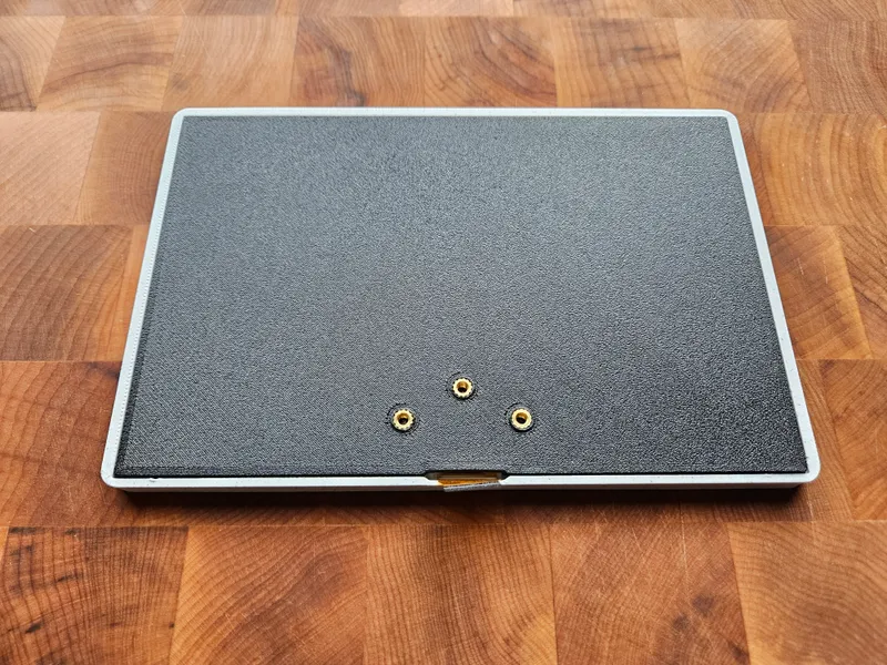
I wanted to ensure support for the FireBeetle 2 with headers and make sure there was a hole to access the reset button if needed (a piece of filament will fit if you do not have something long enough).
This enclosure is a little more complex to assemble than other options for this project, but I think it is worth it for the final design. I have included installation recommendations below to help make assembly as smooth as possible.
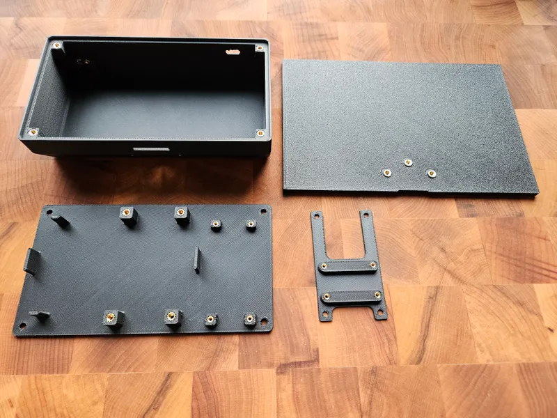
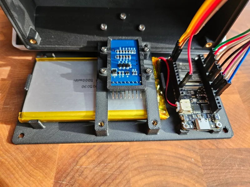
Note: You will see a slight discrepancy in my photos. My original design used four M3 inserts and bolts to connect the adapter tray to the base. In the end it is significantly easier (and serviceable) to only use two. The models have been updated to remove these entirely.
Updates
- April 25, 2024: Added models to support a 906090 battery. I have not tested the fit myself so if you do please share your results.
Bill of Materials
Weather Display:
- FireBeetle 2 ESP32-E
- Good Display 7.5in e-paper (GDEY075T7)
- Good Display DESPI-C02 Adapter Board
- Battery
- PL 905090 3.7V 5000mAh (recommended)
- PL 906090 3.7V 6000mAh
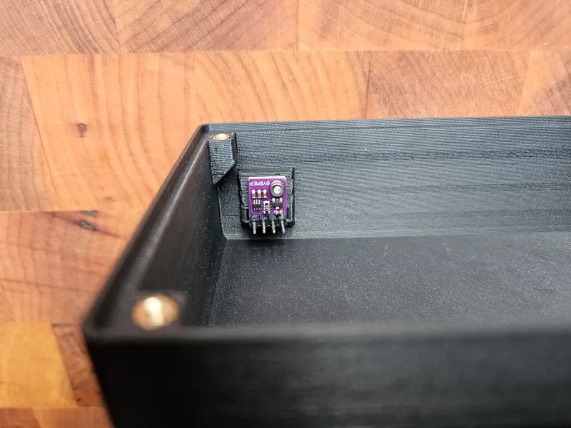
- BME280 5V Digital Sensor (single mount hole)
Enclosure:
- 9x - M2 Threaded Inserts (3.6mm diameter x 3mm length)
- 3x - M3 Short Threaded Inserts (4.6mm diameter x 3mm length)
- 6x - M3 Long Threaded Inserts (4.6mm diameter x 5.7mm length)
- 5x - M2x4mm Socket Head Bolts
- 4x - M2x6mm Socket Head Bolts
- 5x - M3x8mm Socket Head Bolts
- 4x - M3x8 Countersunk Head Bolts
Notes:
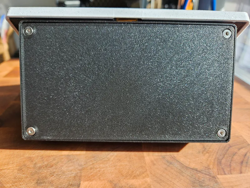
- The design of the base means the countersunk head bolts are a requirement
- It should be possible to use M3 short threaded inserts in place of long if required, but I haven't tested
Print Settings
- 4 Perimeters/walls
- 25% infill
- 0.2mm layer height
- 0.4mm line width
- 5 top and bottom layers
- Parts are pre oriented in the correct position for printing
- No supports needed
Installation Guidelines
Note: Make sure you've connected all your hardware to ensure functionality before installation
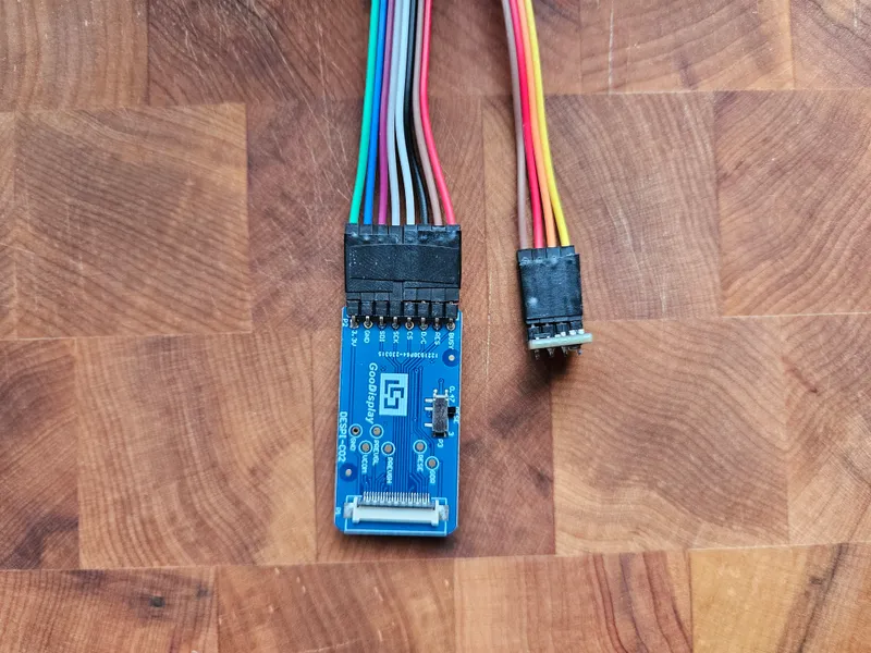
1. Connect cables to FireBeetle and tape the sensor and adapter ends together for easy installation later.

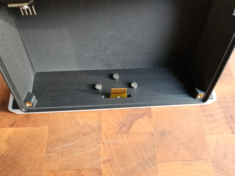
2. Install threaded inserts (the 3 M3 short inserts are for the screen back).
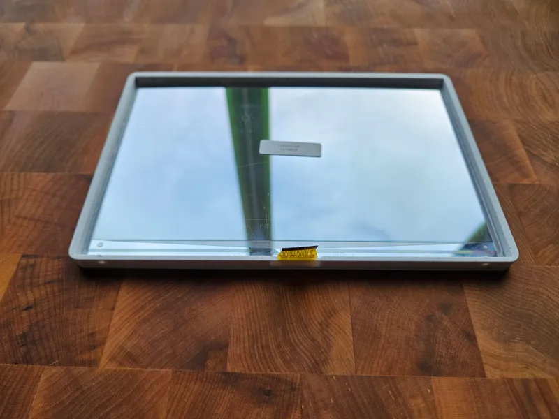
3. Install screen in case (I recommend sliding the top of the back in place and pushing the bottom to snap it in).
4. Install the BME280 sensor with a M2x4mm bolt.
5. Leaving the screen face down, align the enclosure and screw in the three M3x8mm bolts (stop when each bolt has just been threaded until all bolts are attached and then tighten).
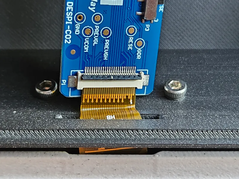
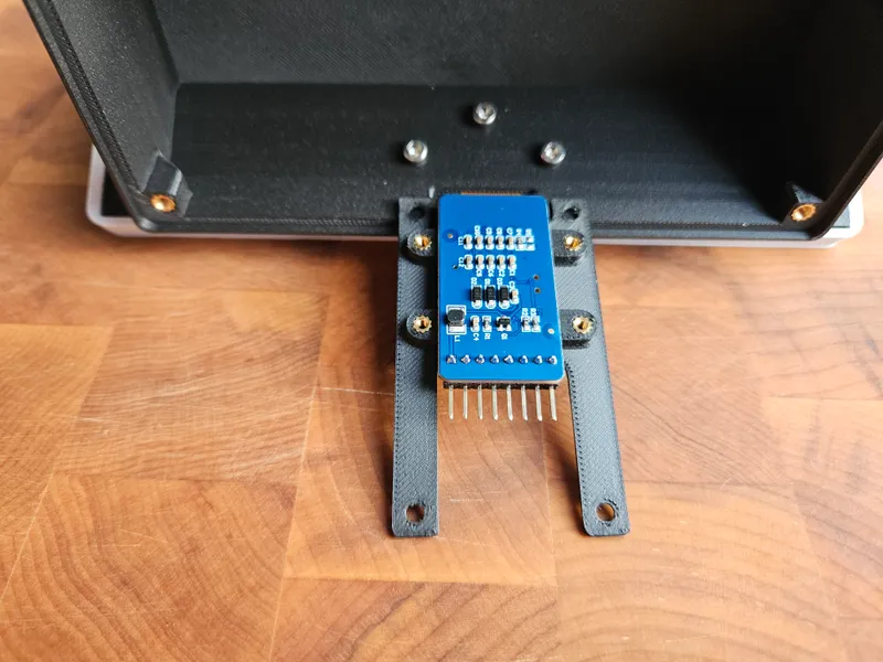
6. Attach the display adapter (You can put some pressure on the cable to help insert it as seen below, don't forget to engage the black clip).
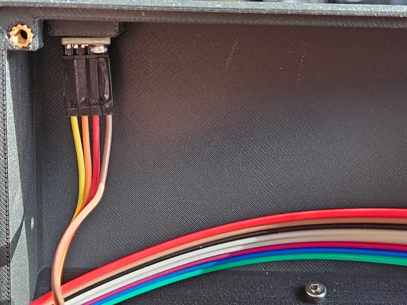
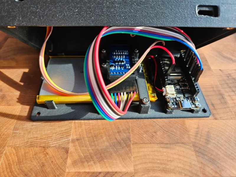
7. Connect the cable to the BME280 sensor
8. Align the display adapter tray and bracket and use two M2x6mm bolts. Then align and connect the adapter to the base with two M3x8mm bolts.
9. Attach the cables to the display adapter, tuck the cables, close the enclosure, and secure with the four M3x8 countersunk bolts.
Tags
Model origin
The author marked this model as their own original creation.


