Lenticular 3D Printing
Description
PDFGeneral Introduction to Lenticular Printing
Flip Cards use Lenticular sheets to show different pictures depending of the angle you are looking at it. Most of the time, it is used to create a 3D effect or a movement effect on a 2D picture.
Lenticular Sheets are made of a series of half-cylinders aligned on a composition of two "striped" pictures. In our example, we will use a white and black picture of a circle:
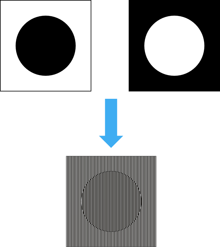
The Lenticular Sheet bends the light in a specific way that allows to see only one out of the two stripes at a time (either the white one or the black one).
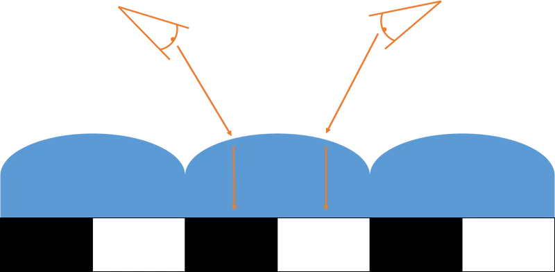
The main idea is to print 2 sets of stripes with a low layer width (e.g., 0.4mm) followed by 1 Transparent Stripe with double the layer width (i.e., 0.8mm).
In order to achieve the more realistic effect, both the picture and the lenticular sheet need to be printed correctly.
This guide provides some tips (both in model creation and slicing) on how to 3D Print a Lenticular Flip Card horizontally. One can rightfully argue that it would be easier to print the picture on a regular printer and 3D Print the Lenticular Sheet Vertically (as shown in other models) but I prefer to 3D print the whole thing horizontally in order to assure the alignment between the stripes and the half-cylinders of the sheet.
Software used:
- Fusion 360 for modelling (.f3d file attached)
- Prusa Slicer for slicing
Printer used: Ender 3 Pro with a 0.4mm nozzle, manually changing filament (I'm sure a multi-material printer can do a better job).
While fine-tunning the different slicer options, it can also be useful to do some test prints, cut them in half and examine them under a magnifying glass to check the quality of the print.
Part One: Modelling Principles
Disclaimer: this section only describes the main idea on how to model the Lenticular Card. Additional modelling tips, to achieve better results, are described in the other sections.
Modelling the base picture may be the most brain-wrecking part of this guide as you will need to alternate Black and White patterns in a predetermined way.
Getting the Striped Base
Start by sketching 2 rectangular shapes of your desired length and width. I recommend a maximum width equals to your nozzle size.

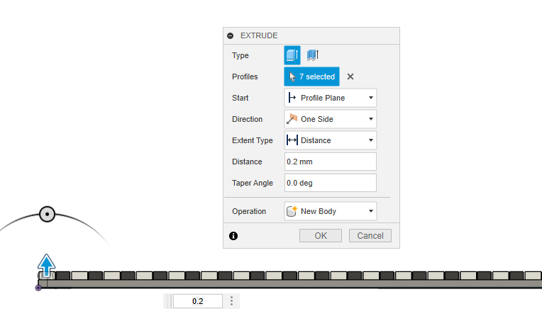
Extrude the 2 rectangles into 2 separate bodies by the size of your regular Layer Height (generally 0.2mm). At this point, I recommend splitting the 2 bodies into 2 different components to ease the rest of the process.
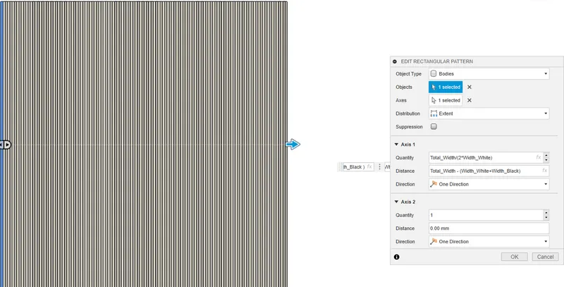
With your first body (let's call it White), apply a Rectangular Pattern:
The “Quantity” parameter should be the number of stripes you want on your picture and will depend on the total width of the picture:
Quantity = Total Width of the Picture / Width of 2 stripes
The “Distance” parameter should be the Total Width of the picture - 2 Stripe's Width (one white and one black).
If you have separated you two initial bodies into Components, the new instances from the rectangular pattern should be created into your White Component as well.
Now apply the same Rectangular Pattern to your second body (let's call it Black).
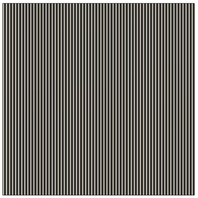
This will give you your Striped Base:
Adding a picture, logo, symbol, etc.
Printing the Lenticular Sheet on this Striped Base will only get you a sheet that shift from White to Black. Until you add a picture to that base. I would recommend something easily discernable with only two colours. We will use a simple circle for this test.
For that, you will need to have your picture in a .svg format.
Add it as a sketch in Fusion, scale it and place it where you want it to be on your Striped Base.
Once you have done so, select all your White Stripes and use the “Split Bodies” tool to split them based on the svg sketch contours.
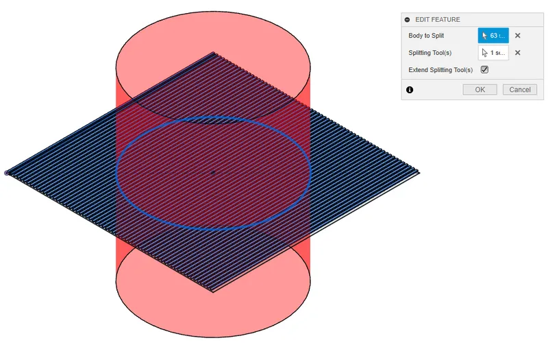
Repeat this step with the Black Stripes.
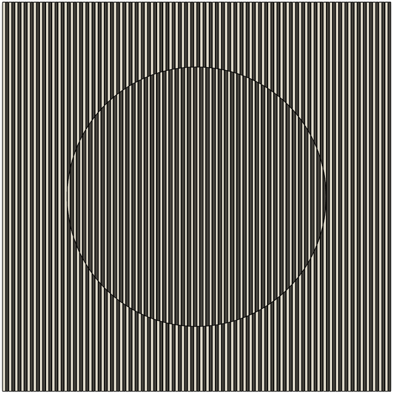
Now that your Base has been split, you just need to invert the colours (aka Parent Component) inside the contours.
To do so, start by selecting all the White Stripes inside the circle, and move them to the Black Component.
Repeat this step with the Black Stripes (except for the one you have just added !) in order to move them to the White Component.
The Final Result should be something like this:
Adding a Base Layer and the Lenticular Sheet
In order for the Striped Base to be printed on something solid (and not directly your print bed), add a Base Layer of the Total Width of your picture by the Total Length of your picture. Extrude it by a multiple of your Layer Height.
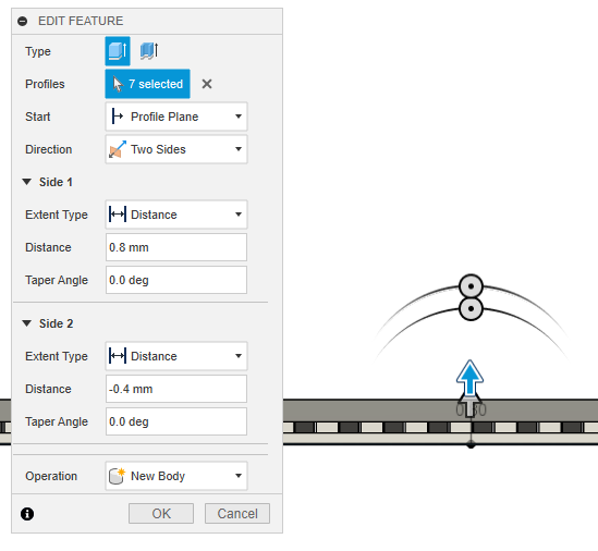
Reuse the sketch made for the Base Layer to Extrude the Lenticular Sheet of the same width and length. The Height of your Lenticular Sheet should be roughly the same as the width of one Stripe (Black or White).
This Sheet should sit at the top of your Striped Base.
Part Two: Printing a clear Striped Base
Printing clear/crisp black and white stripes is crucial to have the desired Flip Card effect. This section will present both modelling and slicing tips that helped me achieve this effect (and yet, my prints are still far from perfect). Depending on your model and printer, these might not be necessary and/or not optimal. You will need some tests and fine-tunning to get it right.
General Slicing Tips
As a starting point, in order to get the right path in the slicer, I recommend setting your Striped Base with 0 Perimeters (use modifiers if necessary).
I also printed this layer at slow speed (25mm/s) in order to get the cleanest lines.
Your retraction settings will also need to be on spot. These will differ depending on your printer and your filaments but consider using settings a bit higher than usual in both retraction length and speed.
It might also be useful to de-activate the Wipe on retract option, as this option forces the nozzle to move back on a line already printed while retracting and it may cause some blops.
My Layer Width was set to 0.3mm in the slicer (instead of the 0.4 set in the model). Just make sure in the Print Preview that the Layer Width matches what was expected in the model (more on that later).
For more complex pictures, if not all stripes are being printed, I recommend playing around with the Slice Gap Closing Radius and try to reduce it. (I personally went from 0.049 to 0.019mm for some of the tests.)
I also found that changing the Perimeter Generator to “Classic” may help in printing the stripes in a (kind of) sequential order.
Avoid second colour overlapping the first one
I found that, often, the second colour being printed will tend to overlap the first one. Leading to Layer Width of the second colour being higher than the first one.
To counteract this effect, we can try to anticipate it while modeling the picture. For example by reducing the Stripes Width of the second colour. For my tests, I used a 0.4mm Width for the White Stripes vs. a 0.34mm Width for the Black Stripes.
Another possibility is to leave room for the filament to ‘bleed’ by creating some slight gaps between each stripe in the model.
Finally, playing around with the Extrusion Multiplier of your extruders (for both colours) can help as well. On the same principle, by reducing the Extrusion Multiplier, you will reduce the amount of filament being pushed which will leave some room for the filament to ‘bleed’. Mines were tuned down to 0.85.
Part Three: Printing the Lenticular Sheet
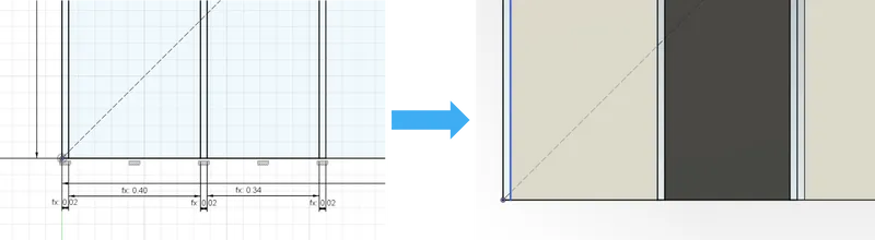
As mentioned previously, correctly printing the half cylinders is critical to get the lenticular effect. Usual printing parameters will lead to a kind of diamond-shaped rectangle as shown in Prusa Slicer previews.
A flat Lenticular Sheet won't bend the light as good as a cylindrical one.
General Slicing Tips
The first thing you will need to modify is the Infill Fill Pattern. In order to be aligned with your Striped Base, set it to “Aligned Rectilinear” with a Fill Angle of 0° or 90° (depending on your printing orientation).
Printing dead-slow (5mm/s) also helped me get the better results.
You will also need to add a Layer Height Modifier in order to get your Lenticular Sheet in one single layer. (Remember that this Layer Height was defined in our model, 0.4mm for me.)
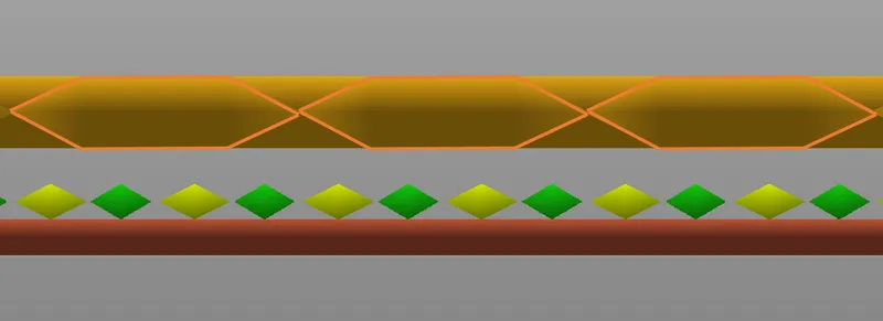
Getting a half-cylinder
The most effective way I found to get this half-cylinder shape is by both:
- Adding a Z-offset in the model (between the Striped Base and the Lenticular Sheet)
- Reducing the Extrusion Multiplier in the slicer
The idea behind the Z-offset is to leave room for the filament to melt instead of ‘spreading’ it as you usually do in 3D Printing (the diamond-shaped rectangle). For my tests, the z-offset was of 0.3mm, so roughly one layer height.
As for the Extrusion Multiplier, I initially tried an increased EM (to try to compensate for the Z-offset), until I made a happy mistake and print my Lenticular Sheet with a 0.85 Extrusion Multiplier, which gave me the best results I've had this far. So I do recommend playing around and reduce this Extrusion Multiplier as well.
Align the Lentitclar Sheet and the Striped Base
As mentioned previously, the main idea of doing a single model and printing it horizontally, is to make sure that the Lenticular Sheet is correctly aligned to the Striped Base.
To do so, we have to make sure that:
- The Layer Width of the Lenticular Sheet should match 2 Layer Width of the Striped Base (1 Black and 1 White)
- Each individual Layer Width of the Lenticular Sheet is aligned to exactly 2 Layer Width of the Striped Base
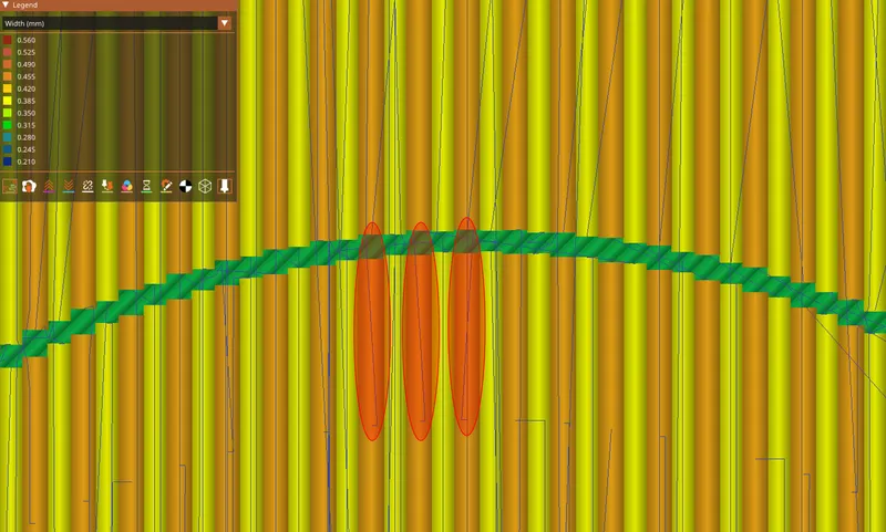
For the first point, I recommend doing a pre-slice with only the Striped Base and look in preview mode what is the exact layer width of the Black and White Stripes. Add them together and put the result as a the Layer Width for your Lenticular Sheet.
Regarding the alignment of each Layers, again, I recommend using the preview mode to do so. If you look at the top or bottom of your print, you can see your Striped Base where the nozzle do a U-Turn while printing the Lenticular Sheet. See below:
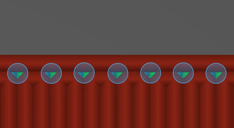
Modify slightly the position of your Lenticular Sheet until everything is perfectly aligned.
What's next?
Well, first, congratulation for reaching this point. I'm sure it wasn't a light reading.
For me it was kind of a proof-of-concept, the “Can I 3D Print this?" type of project.
A few other leads if you are interested in this:
- As mentioned in the intro, I guess you could also print the Striped Base with a regular printer, print the Lenticular Sheet vertically and try to align them both afterward
- I have managed to avoid getting sucked into the FullControl GCode rabbit hole, which I think, with the new .svg integration, may be an option to get better pathways and less retractions for the Striped Base
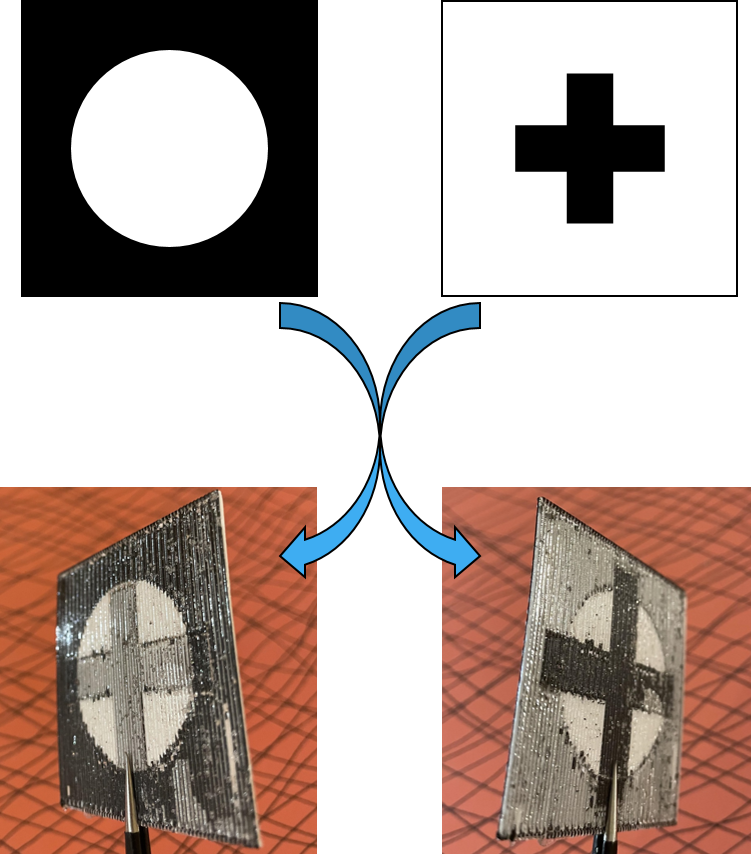
- Theoretically, you can also use two different images rather than two ‘sides’ of the same image. I have tried this with one circle and one cross but ended with some grey areas rather than white ones, see below:
I hope you enjoyed this guide (or at least learn something from it).
Now go out and have fun with Flip Card. Try more complex images, differents settings to get the best effect, whatever you fancy!
Tags
Model origin
The author marked this model as their own original creation.


