Modular Breadboard Kit V2 - small modules only (with STEP files)

Description
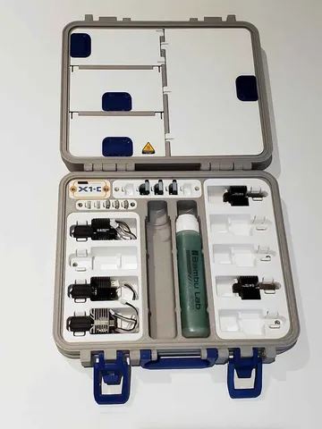
PDFThe idea here was to make a breadboard kit that could be stowed away in a Stanley 014725R case (which would hold 2 of these). This is the second version of the "Breadboad Kit", with the difference being that the smaller modules can now be swapped between the left and right versions.This "thing" only includes the breadboard base and the small modules. I will post files for the larger modules (the DSO and ESR modules) as remixes of this, but if you printed them already from the original (v1) versions, they should still work.
I removed the original versions of the breadboard kit (v1) since there were 4 "things" related to it out there (2 each with left and right versions), and it seemed like a lot of clutter and confusion. I did not see any makes on the original version, so thought it was safe to remove them, sorry if that is not the case. Though if you need any files from the original version let me know. The large modules from the original version should still work with the smaller modules and breadboard base from this (v2) version.
Currently I plan to post the following remixes for the larger modules (they need to be listed separately since they are remixes and have different licensing):
A DSO112A module which will hold a DSO112A mini Digital Storage Oscilloscope (DSO and one DC-DC buck converter (with LCD display). It is available at the link below:
https://www.thingiverse.com/thing:3638866
A 12864 Mega328 ESR Transistor Resistor Diode Capacitor Mosfet Tester module with two adjustable DC-DC buck converters (with LCD displays).
(pending, but available at Instructables)
https://www.instructables.com/id/Component-Tester-Module-for-the-Breadboard-Kit-V2/
Additionally, all the files and instructions needed can be found at the link below for an instructable that covers the whole setup.
https://www.instructables.com/id/The-Modular-Breadboard-Kit-version-2/
https://www.instructables.com/id/Component-Tester-Module-for-the-Breadboard-Kit-V2/
This thing includes the following (small) modules which can be used with either a right or left handed setup:
- Dual voltmeters (versions for both small and large size volt meters)
- Dual Potentiometers
- 2x momentary button switch modules
Momentary button and toggle switch module There are also a left and right versions of the following:
"endcap" module which holds a 170 Tie-points Mini Solderless Breadboard
- base module that holds two 830 pin solderless breadboards, with feet that fit the floor profile of a Stanley 014725R case.
base module that holds two 830 pin solderless breadboards, with a flat base for folks that don't have the Stanley case or want them to have a flat base. The components used were:
LCD voltmeters (these use the "sm" or small modules) if you get the 10x22.5mm versions linked below. If you happen to buy the larger type, then use the LCD parts that have "LG" in the name. I used the small ones (linked above) which use the "SM" modules.
- Mini 25 Point Solderless Breadboard (2 per potentiometer module)
- 170 Tie-points Mini Solderless Breadboard (one)
- 830 point Solderless breadboards (2)
- Some 1 pin dupont connectors (female) and shells will also be needed. You could also use some premade female jumpers with these on the ends, just cut them and use the wires for the volt meters. These are only used in the voltmeter modules and the switch modules.
- "Rotary Potentiometer Panel Pot Linear Taper 500 - 500K Ohm " with caps (available on Ebay). See the pics for an example of the type used. The pots I purchased for this project have a 15mm shaft length (8-9mm knurled part), 6mm shaft diameter and are 24mm overall. I used a mix of ranges, with 1k, 10k (2) and 100k on my setup.
- Momentary switch (these are only needed for the modules with switches)
- Toggle switch AC 250V 3A/125V 6A (this link shows two types, I used the smaller of the switches for the modules with the toggle switch)
Optionally this was designed to fit in a STANLEY 014725R organizer case (Zoro.com is the cheapest place to get these - or Ebay) Hardware:
I used M3 screws and M3 inserts (4mm x 4.3mm) see the list below of the types of screws used.
Potentiometer module
M3x8 (2)
M3x12 (1)
M3 4mm x 4.3mm brass inserts (3)
Voltmeter module
M3x8 (2)
M3x16 (1)
M3 4mm x 4.3mm brass inserts (3)
Switch modules (both types)
M3x8 (2)
M3x16 (1)
M3 4mm x 4.3mm brass inserts (3)
End module (holds the 170 pin Breadboard):
M3x8 (3)
M3 4mm x 4.3mm brass inserts (2)
I hope I did not leave anything off, but you can find more info at the instructable link above on assembly and parts that were used with it.
If you print this, and like it, it would be cool if you can post a make so I know if this is worthwhile. If you have a problem or a question let me know in the comments. I probably printed 30 or more test parts along the way to making this, and so far my kits seem to be working well, so hopefully there are no large problems. However, if you see something that can be improved please let me know and I will do what I can to fix it. The STP file will be included for easy remixing. Thanks for checking this out!
Print Settings
Notes:
The dupont holders were printed in 0.1mm resolution, while the rest was done in 0.2mm (0.25mm would also work).
Please rotate the parts for printing with minimal supports, I did not orient them for printing.
Post-Printing
Assembly Notes
Dupont connectors:
Some glue is required for fixing the Dupont connectors to the housings. For the Dupont holders, I just put a little glue around the inside faces of the printer part and inserted the Dupont connector. The face of the Dupont connector should be flush with the face of the printed part, let it dry before installing it. Glue is not needed on the outside of the Dupont holder.
General:
There are quite a few M3 inserts used in this project, and they should be heat set, but I glued them in on my kits. I decided to glue them in using clear Gorilla Glue since I have no experience with heat setting them, and I feel that with glue they wont get set in askew. I had to be careful to let the glue cure/set fully before putting the screws in and didn't over tighten the screws since the glue will be weaker than melting them in place. I found it helpful to use a 20mm or so M3 screw as a tool to help install the inserts. Inserts should be flush or sit below the surface of the part, none should stick out from the parts.
I included some "dots" than can be taped or glued on the bottom after printing, these are designed to fit the bottom of the Stanley case, but are not required.
Potentiometer Module
Parts:
2 potentiometers with knobs, and their washers and nut, with a 15mm shaft (knurled part is approx 8-9mm)2 Mini 25 Point Solderless BreadboardsM3x8mm screws (2)M3x12mm screw (1)M3 4mm x 4.3mm brass inserts (3)the following printed parts: MBBKV2-D10-mod-pot-BASE
MBBKV2-D10-mod-pot-TOP
Assembly (pics are below):
- Poke the 3 leads/prongs from the potentiometer into one of the short ends of the 25pin breadboard and then rotate the potentiometer 90 degrees so it looks like assembly in the 2nd pic.Gotta do this for the other one too.
- Push the potentiometer and breadboard assembly into the top of the module and secure the nut (3rd pic). If it is tight, please clean the "foot" from the parts (the fit is snug, but not impossibly tight).
- To assemble the module, install the M3 inserts as shown in the 1st pic, for every screw, there will be an insert.
Follow the 1st pic to install the screws, you can wait to install the M3x8mm screws until later when doing the final assembly. The two pegs in the bottoms of the mini breadboards will seat into the holes in the base of the module, if they do not, clean up the parts with a deburring tool to remove the "foot" from printing. LCD Voltmeter Module
Parts:
Mini 2 wire LCD volt meters (2) one pin female Dupont connectors (4) M3x8mm screws (2) M3x16mm screw (1) M3 4mm x 4.3mm brass inserts (3) the following printed parts: MBBKV2-D10-mod-SM-LCD-BASE -or- MBBKV2-D10-mod-LG-LCD-BASE
MBBKV2-D10-mod-SM-LCD-TOP -or- MBBKV2-D10-mod-LG-LCD-TOP
MBBKV2-D10-mod-dupont (4 of these)
Note: Most of these small volt meters have a pot on the back that can be used to fine tune them if they are not reading correctly. I only had to adjust mine slightly so it hopefully is not a big deal, but may be worth checking before assembly.
Assembly (see pics below):
First install the Dupont connectors on the 2 wires attached to the LCD Voltmeters. You should leave about 1.5" to 2" of tail on these (see the 1st pic and the 2nd pic of the partly assembled LCD module). You need enough to work with, but these will eventually need to be tucked into the housing so keep em as short as possible. You may want to add some hot glue to where the wires attach to the boards since that is an area where they could break. Alternatively, if you do not want to deal with crimping the Dupont connectors, you can get jumpers with the female Dupont connectors, and just cut one end off and solder that wire to the LCD voltmeters in place of their existing leads.
- Glue the Dupont connectors into the "MBBKV2-D10-mod-dupont" parts (1st pic). Use just enough glue around the sides to hold the connectors, but not too much that oozes out. The front of the Dupont connector should be flush with the top of the part and should not stick out. Allow these to dry before moving on.
- Install the LCD Voltmeters in the module, and take note of their orientation (you don't want them to be upside down when you look at them). They will be a tight fit, and if you find they will not go, you may need to clean up the "foot" on the part or lightly sand the inside of the part.
- Install the Dupont connectors into the holes in the top module parts (see the 2nd pic of the partly assembled LCD module). Don't use glue on these. They will be a snug fit, but if you run into a problem it is probably easiest to lightly sand the outside of the Duponts and clean the "foot" from the openings in the "top" module part where they need to go through.
- Once the Dupont connectors are all installed, the wires from the Duponts should be arranged so they will sit in the small gaps provided for them next to where the Duponts go in, and then coil or flatten the remaining wires so the case can be closed up. Be careful not to pinch the wires when closing it up. It may help to use some hot glue to hold the wires down.
- To assemble the module, install the M3 inserts by melting them in place as shown in the 3rd pic, for every screw, there will be an insert.
To close up the case, the wires will need to be arranged so they do not pinch (a lot of excess wire can be a problem here and may need to be re-worked with shorter wires). The wires that go to the Dupont connectors should be arranged so they do not pinch and are set in the corresponding grooves in the top part of the case (see the 2nd pic where one of these is highlighted). When the wires are situated out of the way, the case can be closed up using a M3x16mm screw through the top of the case, into the insert embedded in the base. The M3x8mm screws can wait until later, when doing the final assembly. Momentary Button and Switch Modules
Parts:
momentary switch and cap (qty 1 or 2 depending on the module) small toggle/rocker switch AC 250V 3A/125V 6A (qty 1 - or none depending on the module) one pin female Dupont connectors (4) M3x8mm screws (2) M2x16mm screw (1) M3 4mm x 4.3mm brass inserts (3) the following printed parts: MBBKV2-D10-mod-2xmom-switch-BASE -or- MBBKV2-D10-mod-mom-toggle-switch-BASE
MBBKV2-D10-mod-2xmom-switch-TOP -or- MBBKV2-D10-mod-mom-toggle-switch-TOP
MBBKV2-D10-mod-dupont (4 of these)
Assembly:
To assemble the module, install the M3 inserts as shown in the 1st pic, for every screw, there will be an insert.
- Install the Dupont connectors on the 2 wires attached to the momentary switches and/or toggle/rocker switches. You should leave about 1.25" to 1.5" of tail on these (see 2nd and 3rd pics). You need enough to work with, but these will eventually need to be tucked into the housing so keep em as short as possible. You may want to add some glue to where the wires attach to the switches since that is an area where they could break. Alternatively, if you do not want to deal with crimping the Dupont connectors, you can get jumpers with the female Dupont connectors, and just cut one end off and solder that wire to the switches.
- Solder wires with the Dupont connectors to the momentary switches and/or toggle/rocker switches, and insulate the connections with heat shrink, electrical tape or liquid electrical tape.
- Install the Momentary switch by snapping it into the "top" part, be careful however since the tabs are fragile (see the last 4 pics).
- Install the toggle/rocker switch, it should press into place and latch.
- Glue the Dupont connectors into the "MBBKV2-D10-mod-dupont" parts (2nd pic). Use just enough glue around the sides to hold the connectors, but not too much that oozes out. The front of the Dupont connector should be flush with the top of the part and should not stick out. Allow these to dry before moving on.
- Install the Dupont connectors into the holes in the top module parts (see the last pic for the LCD module which is similar). Don't use glue on these. They will be a snug fit, but if you run into a problem it is probably easiest to lightly sand the outside of the Duponts and clean the "foot" from the openings in the "top" module part where they need to go through.
- Once the Dupont connectors are all installed, the wires from the Duponts should be arranged so they will sit in the small gaps provided for them next to where the Duponts go in (see the 3rd pic where one of these grooves is highlighted). Then arrange or flatten the remaining wires so the case can be closed up. Make sure the wires will not get pinched in the case or by the screws. It may help to use some hot glue to hold the wires down prior to closing the case.
Close up the case, but do not pinch the wires. Use the M3x16mm screw through the top to hold the case together. You can wait to install the M3x8mm screws until later when doing the final assembly Final (finally) assembly
Gather up the 4 modules you want to use (they should be mostly assembled by now), the end module that holds the 170 point breadboard, the large module (DSO112A module or the ESR module), a wire comb (either the A+B parts of the whole comb), and finally the breadboard base which will hold two 830 pin breadboards.
The assembly will use M3x8mm screws for the smaller modules and a mix of M3x8 and M3x16 screws for the larger module (to see where to use the 16mm screws, see the diagrams for the assembly of the larger module). If you already installed screws in the holes in the large (DSO112A) module where there are rectangular pockets in the base, those screws will need to be removed since they will also hold the breadboard base.
The tabs on the base will insert into the pockets in the large and small modules, if the fit is tight you may need to clean up the tabs on the base with sandpaper to remove any foot or excess material. They will be a tight fit but they should go in.
I started by installing the large DSO112A module onto the base first, next was then the end module which holds the 170 point breadboard and then the smaller modules. The order does not really matter though, the modules can go in pretty much in any order.
After all the modules are installed in the base, the comb can be installed (3rd pic). It will use M3x8mm screws which go through the comb into the small modules and the end module. The comb has a ledge that helps align and hold the smaller modules, if there is a problem getting the screws in, check that the module is seated correctly on the comb and the parts are cleaned of any excess plastic. Once all the modules are installed it should be pretty sturdy, and the breadboards can be stuck in their places using the double sided tape (see the pics).
If you use the base designed for the Stanley 014725R organizer case, you can also print the small "dots" and half dots" and tape or glue those on the other parts that have been assembled if you feel it is too unstable when removed from the case. If you use the flat bases then you will not need the dots.
Please just take note of the specs on the DC-DC converters and LCD modules being used so they don't get fried or the fuses get blown. I am using a 19V 1.8A power supply with mine which seems to work well.Also, since the DC input and DC output connectors are of the same type (the 2.1mm jacks), take note of which is which, and you may want to label them for good measure.
If you find these models useful, please post a like or a comment with some pics of your prints.
You can find the other things I'm working on at my blog here. You can also follow me here on Printables to see what new stuff I post. Thanks for looking!
===================
This was designed with ViaCAD V9
Category: Electronics
How I Designed This
Tags
Model origin
The author marked this model as their own original creation. Imported from Thingiverse.