Bluetooth AV media control foot pedal
Description
PDFIntroduction
I use my iPad to view online video guitar lessons, where I constantly have to pause or rewind the last few seconds of the video. I was getting frustrated, as I kept accidently tapping the timeline instead of the video control I wanted, and ended up loosing my place int the video. I decided to build a foot pedal to control the video playback.
General Description
The foot pedal uses a low cost ESP32 DEVKIT 1 micro controller and footswitches to send keyboard key presses via Bluetooth to a tablet or computer. It was designed to control audio and video playback, but could potentially be used to control any application that accepts keyboard input.
Note: the ESP32 uses low energy Bluetooth, this may not work with older Bluetooth receivers. It works perfectly with my old iPad Air2 and my PC with a Bluetooth 5 dongle. Bluetooth low energy came in with Bluetooth 4.0 in December 2009.
The pedal is powered by the USB connector, however there is room in the case so that it could be modified to be powered by a battery or power supply.
It has a pushbutton on the rear that allows the function of the footswitches to be changed and I've set up the software so that in mode 1 it can control YouTube and Licklibrary.com videos, and in mode 2, my iPad's music player. The current operating mode is indicated by the two LEDs on the top of the case. The software also has a mode 3 that could be activated for other tasks and it is straightforward to alter the software to implement this or change the keystrokes sent. The software has set up the footswitches as shown on the following tables.
In mode 1 video control, the foot switches are set to:
| Footswitch | Key sent | Function |
|---|---|---|
| A | < | Slow video playback * |
| B | > | Speed up video playback * |
| << | LEFT_ARROW | Skip back 10 seconds |
| >|| | SPACEBAR | Play / Pause |
| >> | RIGHT_ARROW | Skip forwards 10s |
* The slow down and speed up video playback functions do not work with the licklibary.com video player.
Note: On a tablet or mobile device, these functions may only work in full screen mode and you may have to request the YouTube desktop site to get a video player with the necessary controls at the bottom of the screen.
In Mode 2 for audio playback, the foot switches are set to:
| Footswitch | Key sent | Function |
|---|---|---|
| A | KEY_MEDIA_VOLUME_DOWN | Reduce sound volume |
| B | KEY_MEDIA_VOLUME_UP | increase sound volume |
| << | KEY_MEDIA_PREVIOUS_TRACK | Skip to previous track |
| >|| | KEY_MEDIA_PLAY_PAUSE | Play / Pause |
| >> | KEY_MEDIA_NEXT_TRACK | Skip to next Track |
Materials Required
To build the foot pedal, you will need the following components:
- 1 x ESP32 DEVKIT1 https://www.bitsboxuk.com/index.php?main_page=product_info&cPath=302_312&products_id=3491
- 5 x momentary foot switches https://www.bitsboxuk.com/index.php?main_page=product_info&cPath=116_128&products_id=3060
- 2 x 15 way single row header sockets https://www.bitsboxuk.com/index.php?main_page=product_info&cPath=225_230&products_id=2879
- 2 x 3mm LED holders https://www.bitsboxuk.com/index.php?main_page=product_info&cPath=172_239&products_id=1816
- 2 x 3mm Red LEDs https://www.bitsboxuk.com/index.php?main_page=product_info&cPath=172_176&products_id=1338
- 1 x momentary push switch https://www.bitsboxuk.com/index.php?main_page=product_info&cPath=116_129_131&products_id=893
- 1 x 50mm x 70mm fibreglass perf board https://www.bitsboxuk.com/index.php?main_page=product_info&cPath=238_244&products_id=2527
- 6 x 10K resistors https://www.bitsboxuk.com/index.php?main_page=product_info&cPath=83_84_85&products_id=456
- 2 x 330R resistors https://www.bitsboxuk.com/index.php?main_page=product_info&cPath=83_84_85&products_id=439
- Various colour hook up single core hook up wire for the perf board circuit.
- Various colour stranded wire for connecting the switches 22 -24 AWG
- 3 x self tapping screws for lid.
- 2 x small self tapping screws to hold down the Perf board.
- 3 x two pin plugs and right angle sockets*
- 1 x 6pin connector and right angle socket* https://www.bitsboxuk.com/index.php?main_page=advanced_search_result&search_in_description=1&keyword=Jst .
*I used JST-XH connectors, as that was what I already had to hand .The switch and LED wires could alternatively be soldered directly to the perf board.
Note: the XH connectors are tight up against the lid support pillars, larger connectors would need to be put in a different place, and require an alteration to the PCB Layout. See Pic1 below.
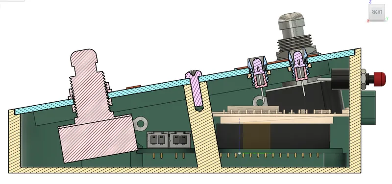
Pic1 - Section though the centre of the pedal
The Software
Software Applications Required to build the software
There are instructions on the following website on how to set up the software needed to program the ESP32 DEVKIT1 https://randomnerdtutorials.com/getting-started-with-esp32/ . I used the Arduino IDE Version 2.3.0 without any problems.
In addition you’ll need the BLE Keyboard library from https://github.com/T-vK/ESP32-BLE-Keyboard . Release version 0.3.0 has a bug that shows up when connecting to a PC, so use 0.3.2-beta or later version. To install it on a PC download the ESP32-BLE-Keyboard.zip fie. Unzip it, then move the ESP32-BLE-Keyboard directory to \Arduino\libraries directory in your documents folder.
My software is here in a text file called bluetoothFootswitch_V2.txt in the download files section.
Compiling the software and copying it to the ESP32
Once you have the Arduino IDE and BLE Keyboard library installed, download bluetoothFootswitch_V2.txt from the files section and open it in a simple text editor e.g. notepad on the PC.
Open the Arduino IDE and create a new sketch, then delete the default code in that sketch. Copy my entire code from the text editor and paste it into the sketch. Now connect your ESP32. Select ESP32 DEVKIT V1 from the list box at the top of the IDE. You may need to search for your board if it isn't displayed straight away. Once you have selected the board, the com port it is connected to, will be displayed in the middle section of the list box. Click the com port to select it.
I would recommend, setting up the circuit on a breadboard and testing the input and output pins are suitable for your particular ESP32 before soldering the perf board ( I had to make a change after I’d soldered it, which made mine not as neat as the revised design here).
Make sure you have already installed the BleKeyboard library then test everything is ok by clicking the check mark at the top of the IDE to verify the code.
Save the sketch as bluetoothFootswitch_V2
How to Configure my software
The settings that can be changed to alter the operation of the foot pedal, are near the top of my code between two underscored comment lines.
The first item is a variable called maxMode, that sets the maximum number of modes the pedal uses. This must be an integer between 1 and 3.
// the maximum mumber of modes to use must be between 1 and 3
int maxMode = 2;
The next section of the configuration code, is where any additional keys can be added, ready to be assigned to a footswitch later. Standard keyboard keys are set equal to the ascii value of the required key. See https://en.wikipedia.org/wiki/ASCII for tables of values.
// declare any KEYS you need that are not in BleKeyboard.h
const uint8_t KEY_SPACEBAR = 32; // SPACE ‘ ‘
const uint8_t KEY_A = 65;              // A Example for letter A
In the BleKeyboard.h file that is part of the BLE Keyboard library, there are lots of other already declared keys you can also use to assign to a footswitch. These do not need to be redeclared in the above Keys section to be used. To view the BleKeyboard.h file, right click the #include <BleKeyboard.h> statement at the top of my program, and select Go to Definition in the pop up menu and the file will load in a separate tab.
The next section in my program, is for setting the ESP pin numbers that each footswitch and LED are connected to. The example below sets footswitch1 to pin D2 of the ESP32. If your using different pins you will need to make changes here.
// Set ESP32 pin numbers for the footswitches and LEDs
const int footswitch1 = 2;
Following that, is a section to allocate the keyboard key that's sent when a particular footswitch is pressed. To change the function of a footswitch, make changes here.
// Assign keys to footswitches
// Standard keys are type const uint8_t
// Media keys are type const MediaKeyReport&
// KeyMode 1
const uint8_t Mode1_FSwitch1 = KEY_LEFT_SHEVRON;
const uint8_t Mode1_FSwitch2 = KEY_LEFT_ARROW;
const uint8_t Mode1_FSwitch3 = KEY_SPACEBAR;
const uint8_t Mode1_FSwitch4 = KEY_RIGHT_ARROW;
const uint8_t Mode1_FSwitch5 = KEY_RIGHT_SHEVRON;
// KeyMode 2
const MediaKeyReport& Mode2_FSwitch1 = KEY_MEDIA_VOLUME_DOWN;
const MediaKeyReport& Mode2_FSwitch2 = KEY_MEDIA_PREVIOUS_TRACK;
const MediaKeyReport& Mode2_FSwitch3 = KEY_MEDIA_PLAY_PAUSE;
const MediaKeyReport& Mode2_FSwitch4 = KEY_MEDIA_NEXT_TRACK;
const MediaKeyReport& Mode2_FSwitch5 = KEY_MEDIA_VOLUME_UP;
Standard keyboard keys use the data type const uint8_t and special keys for audio playback and other functions are of data type const MediaKeyReport&. So if you want to replace a standard keyboard key with a media control key, you must change the data type accordingly. There can be mixed data types within modes.
I’ve tried to keep the programming as simple as possible so it’s easier to be understood by all including me.
Compiling the program and uploading to the ESP32
Compile the program and upload it to the ESP32 using the right arrow button at the top of the Arduino IDE. As this happens info will scroll in the bottom window and if all's well end with:
Leaving...
Hard resetting via RTS pin...
A Serial Monitor tab will then appear in the bottom window of the Arduino IDE. Click the Serial Monitor tab and you may see some gobbledygook like:
����1����B)?�This is normal until the serial connections sort themselves out. Go into Bluetooth setup on your tablet or computer, and after turning Bluetooth on, you should see the ESP32 listed as BTKeyb. Once you have made the Bluetooth connection, the Serial monitor will add BLE connected to the output, and LED 1 on the foot pedal will turn on. Every Time a foot switch or mode switch is pressed, confirmation will be sent to the serial monitor which can be useful, if something isn't working as expected.
����1����B)?�Set up complete. Waiting for BLE connection...
BLE connected
Setting mode to 1
 Switch on pin 4 has been pressed
Switch on pin 18 has been pressed
Switch on pin 27 has been pressed
Mode change called from switch on pin 27 Setting mode to 2
Constructing the Electronics
Dg1 drawing below shows the wiring and the header sockets for the ESP32. The ESP32's USB socket would be at the top of the drawing if the unit had been shown installed. The ESP32 pins used, are indicated by the labels adjacent to the header sockets. Wiring on the top of the perf board is shown in wider coloured lines with solder points shown with a grey circle. The wiring underneath the board is shown in thinner green lines with solder points indicated by green circles. I found it best to strip a section off the end off the top wires pass the stripped end through the hole and continue the run on the underside of the board as necessary. Tip: A small piece of damp tissue on the wire sleeving help stop the sleeving melting when your soldering the wire.
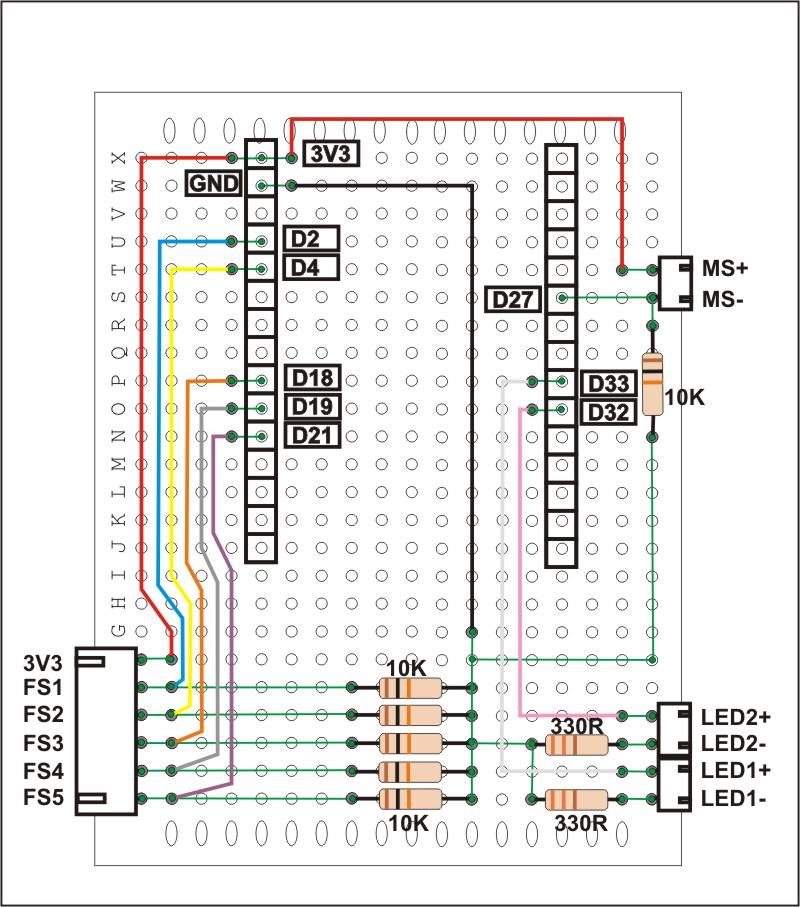
Key: MS - Mode Switch. FS - Footswitch
Dg 1 - Perf board wiring (don't miss the white wire from LED 1 +ve to D33)
Constructing the Switch and LED wiring.
Print the foot pedal lid and under lid stiffeners and assemble these with the footswitches and add the LED holders. Wire up the footswitches and LEDs as shown on dg2 below. Double check the LED polarities before connecting and don't forget to slip on the led holder bung before soldering.
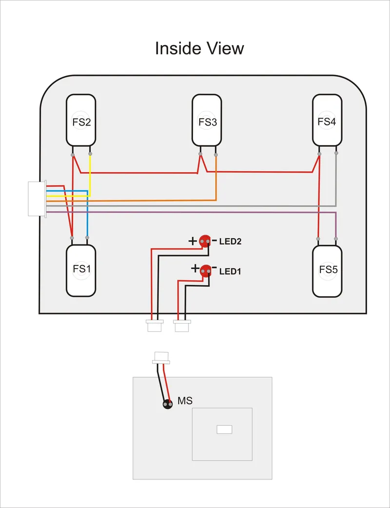
dg2 - Inside lid and back plate
Printing the case
I printed my foot pedal case in PETG with variable layer hight activated. I designed the lid to print flat so that I could use a colour change to print the button labels. I added the lid stiffeners under the lid for extra rigidity. The stiffeners are held in place by the footswitches. If you are printing in PLA, the lid stiffeners may not be necessary. I would also suggest printing the the lid with 100% infill as with standard settings there were only 2 layers of infill anyway.
I designed the back plate to be a separate component from the foot pedal base, so that if the hole for the USB socket is not in the right place, it can be easily modified and just the back plate reprinted, without having to reprint the entire base part again. I added a rectangular support to the plate for the USB plug as the USB port on the ESP32 seemed a bit vulnerable to being flexed. This means the plate will need to be printed with the inside face down and support material will be required for the recesses.
Support material will also be needed for the Perf board clip in the foot pedal base.
Final Assembly
Install the rear push switch into the back plate. Insert the programmed ESP32 into the perf board circuit and plug in the footswitches, LEDs and rear push switch. While keeping the perf board tilted, slide it partially into the clip in the base plate. Keeping it tilted slide in the back plate until the back of the ESP32 is in the back plate's recess, then slide the back plate down and perf board down until fully seated. Check the ESP32's USB socket is lined up with the hole, by plugging in the USB cable, Then fix down the perf board with the two small self tapping screws. Finally put on the assembled pedal lid and fix down with three self tapping screws.
Final Comments
This has worked flawlessly with my iPad which is it’s main use. On my windows 11 PC I've had a couple of occasions where it appears not to be working. To fix this, I've deleted it from the list of Bluetooth devices and then reconnected it again. I have tried using it in fusion 360, but keystrokes were ignored, However, I have had it working, sending keystrokes to a PC game successfully.
Update 15/2/24: The pc connection problems are fixed in the latest v0.3.2-Beta version of the ESP32_BLE_Keyboard library. I have also updated the instructions on how to load this library.
New Experimental code V3
I have added some experimental code that adds the ability to use a long press of the play button, footswitch 3 to send a different key press. See the makes & comments section. There is a new configuration section of the code for this.
// Long Press                                  // #### Experimental long Press code added ####
const int LONG_LOOP_COUNT = 2;                 // ### change this value to adjust lenght of press requied to trigger.
// Long Press Keys
const uint8_t LongPress_FSwitch3 = KEY_LEFT_ARROW;  // ### only Foot switch 3 has long press code
The constant LONG_LOOP_COUNT can be used to adjust how long the footswitch needs to be pressed to generate a long press. The constant LongPress_FSwitch3 holds the keyboard value that's sent with a long press
 if (digitalRead(footswitch3)) {
      if (DebounceSwitch(footswitch3)) {          //### debounce function moved and used to indicate long press
        bleKeyboard.write(LongPress_FSwitch3);    //### if using iPad send multiple 5 sec rewinds
        bleKeyboard.write(LongPress_FSwitch3);
        bleKeyboard.write(LongPress_FSwitch3);
        Serial.println("FS3 has had aLong Press");
      } else if (KeyMode == 1) {
        bleKeyboard.write(Mode1_FSwitch3);
      } else if (KeyMode == 2) {
        bleKeyboard.write(Mode2_FSwitch3);
      } else if (KeyMode == 3) {
        bleKeyboard.write(Mode3_FSwitch3);
      }
The long press can be used to send multiple keyboard keys. This could be needed if sending rewind commands to YouTube from an iPad, where the 10 second rewind key j doesn't work. So you could send three KEY_LEFT_ARROW instead as shown in the above code segment.
Tags
Model origin
The author marked this model as their own original creation.


