Gridfinity Clickfinity Baseplate w/ Connectors

Description
PDFTable of Contents
- Overview
- File Name Convention
- Instruction for Use
- How to use the .f3d file in Fusion 360
- "Alt File's" Purpose
Overview
The primary change with his design is in the default ability to combine edges to the baseplate.
You no longer need to print off separate small connectors to link grids when you have a grid larger than 5x5. They can be printed pre-attached. Detailed instructions below, but the TL;DR is: Create the parametric size in Fusion and then select the sides that you want, combine them, export as a STL and Bob's your uncle.
Daniel @d_mg_305332 remixed version provides a flush side to butt right up to the edge of a drawer. It frees up about 1cm, but that can be the difference of a 5x5 fitting or not. Originally, I didn't need this for the drawer I was building bins for, but I'm happy to see the remix! His remix is here!
File Name Convention
I have created a file name convention that identifies what the file represents.
2x2_GC_w_EC_NESW.stl
Breaking this file name down you can read it as:
“2x2” = 2 height by 2 width grid
- Size of grid not including the edges that may or may not be added
“GF” = Gridfinity Clickfinity
- Name of design for searchability
“w” = with
- An alternative letter you might see used can be “wo” which means ‘without’
"EC" = Edge Connector
- Name identifier for edge connectors being included in design. Omission of this means it's just the grid.
“NESW” = North, East, South, West edges
- This indicates the side of the design that has edges included. The file name can have any letter combination so long as it represents the sides that have edges attached.
Instruction for Use
If you don't see the size you need, this solution is designed for you to make it yourself. It can be made via the .f3d file that has been shared. I will share those instructions below, but it is also something I can make for you if you message me. Eventually, all of the sizes will be added, and I'll be able to remove this section.
How to use the .f3d file in Fusion 360.
- Watch the video I uploaded to YouTube HERE (this might be all you need to see)
- Open the .f3d file
- Use the parametric function to set the number of rows/columns
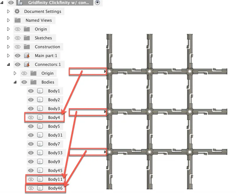
- Hide the connectors that you don't want/need as shown below
- Select the remaining parts that are left showing and 'Combine' them into one part using the function shown below under the 'Modify' tab.

- Export the file as a .stl file and then you will be able to use it in any 3d slicer
"Alt File's" Purpose
I've included a alternative design that is almost identical to the PRIMARY version, but it has fewer holes than the primary one. It was an unintentional design oversight, but I can see it potentially resulting in a little bit of time saved on larger grids.
Note: I will very likely review the time differences and update them here when I get back to my printer.
Tags
Model origin
The author remixed this model.


Differences of the remix compared to the original
This is 100% a remix of @NoWarrenty's Clickfinity baseplate. It's a great design, and after sharing with him this idea he suggested I remix it because he agreed it made sense.
I updated the design to provide users with an new baseplate that when used correctly, does not require printing separate connectors to join 2 grid baseplates.
Benefits include:
- All the same benefits of the Clickfinity design
- A more rigid design because your connections aren't individual connectors anymore
- The ability to fit 6x6 grids on a 256x256mm plate
- Fewer parts to print to complete a grid
- [tbd]Possibly faster print times with the
alt filedocumented below


