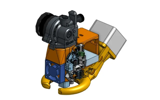
Brass Trimmer Adapter for Makita Trim Router

Description
PDFUse at you own risk. I have only just started testing this design, so It's very much a work in progress. It is theoretically possible for the adapter to break catastrophically and drop a spinning router in your lap.
Both Step and STL files included. Step are higher quality, but not all slicers support Step. Either one should be fine. Use Prusa Slicer if you're not sure where to start.
Due to the elevated temperatures of the trimmer as it runs for extended periods, this should be printed from ABS, PC-ABS, PC, Nylon or similar high temp materials. Glass or Carbon fiber fillers should work fine but are untested. PETG might work but is likely on the edge with it's moderate glass transition temp. PLA is unsuitable.
Layer strength is critical for durability on this design. Run the hotend as hot as possible while maintaining good print quality.
Change Log:
- 23.10.02 - Changed Adapter to v2.1 - Extended router clamp section to improve grip. Increased clamp gap to insure it doesn't bottom out when tightening. I found over extended trimming sessions that the Router would move slightly away from the die. It is advisable to re-torque clamp screws after 10-20min of trimming to insure the router is still being held securely as the adapter warms up.
- 23.10.03 - Increase tool extension out of collet to 31mm
- 23.10.05 - Minor changes to vacuum adapter and cap. Added pads to make print with higher shrink material easier.
Adapter V2.1
- Orient with round pads on the printer bed
- Trim off pads with a sharp knife after print is complete
- Use 5 perimeters, 40% infill
- Print the first 19.5mm at a 0.15mm layer height to insure good thread definition
- Print the remaining part at 0.25mm
- Threads should fit the die tight, it should be difficult to thread the die in by hand. Use horizontal expansion in the slicer to adjust fit if needed.
- Use 3x M4 heat set inserts for the trimmer clamp
- Use 3x M4x14 pan head screws and washers for the trimmer clamp
- Use 3x M3 heat set inserts for the die retention set screws (Holes are intentionally small to improve insert strength, clean melted plastic before use.)
- Use 3x Brass M3x5 cup/flat point set screws for die retention (brass to reduce marring of the die threads)
Vac Adapter
- Place flat face on the printer bed with tube extending straight up
- Use 2x M4 heat set inserts
- This is designed to work with my Shop Vac brand vacuum. It is unlikely I'll make versions to support other brands.
Cap, Vac adapter
- Place flat face on printer bed
- Use 2x M4x10 pan head screws to attach to Vac Adapter
Makita ¼" Trim Router RT0701C
(Harbor Freight has clone that appears identical for much less. I haven't tested it, but it should be a way to save a bunch if that's your thing. I got my Makita for much less than the current asking price.)
Amana 3/8x1/2 Router Bit /w ¼" Shank #45475
Remove the collar and bearings
This must extend out of the trimmer collet by 31mm (+/-0.5mm)
Whidden 300 Blackout Trim Die
(It's possible this would work with Dillon/GSI/Lyman/Other trim dies, but I don't know. It is critical that threads be the same and the distance from the back of the die to the face where neck extends be 30mm)
Setup
- Use already trimmed brass to setup the forming die and get the headspace correct. A Sheridan chamber gauge is highly recommended (avoid the Wilson headspace gauge, it will likely make you sad and confused.)
- Thread the adapter onto the Whidden trim die until the top of the die is flush with the inside face of the adapter. Lightly tighten the three M3 setscrews on the adapter to prevent the die from being able to rotate.
- Make sure the bit is very tight in the router collet and extends out exactly 31mm.
- Slide the router into the adapter until there is about 1mm gap between the bit and the top internal face of the trim die. Moderately tighten the three M4 clamp screws on the adapter body to hold the router in place.
- Start the trimmer and set it's speed to 4. I don't know if this is the ideal speed, but it has been working for me.
- Trim the first piece of 556 brass by feeding it with a smooth stroke of the press handle. It doesn't have to be slow, but care should be taken to avoid abruptly jamming the brass into the cutter.
- I like to double bump by lifting the press handle just enough to move the ram down ¼" and then back to the cutter to insure the both the forming and trimming is consistent. This also helps eliminate any burs on the outside corner of the mouth.
- Remove this piece and check it in the chamber gauge to insure it is near min brass spec.
- If you need to adjust the forming die, do that first until headspace is good.
- When headspace is good, measure case length. If the case is too long, loosen the three M3 set screws and rotate the adapter down (CW) 90deg. If it is too short rotate it up (CCW) 90deg. Retighten the set screws.
- Continue adjusting until length is good.
- Setup is complete.
Model origin
The author marked this model as their own original creation.