Prusa MMU2S with Original Prusa Enclosure

Description
PDF
WORKS WITH MMU2 and MMU2S
Introduction
This four part model connects MMU2S of Prusa with the Original Prusa Enclosure.
Although the intended use of a Prusa printer that features the MMU2S is functional with the Original Enclosure it can be improved.
Instead of placing Prusa’s MMU2S on top of the printer this design places the MMU2S on the outside of the Enclosure.
Due to this placement there come several benefits to enjoy.
- Maintenance of MMU2s without opening Enclosure
- More Vertical Space inside Enclosure (Useful if fire extinguishing system is installed)
- Better Connection possibilities to a filament box
- Better access to buttons of MMU2S
- Only one Bowden Tube needs to enter the Original Prusa Enclosure instead of five
Needed parts:
All four prints are needed to successfully install this modification.
- New handle for the Original Prusa Enclosure with a cable passthrough
- Base for mounting MMU2S on top
- Mount for the board of MMU2S on the side
- Bowden Tube pass through (Consists of 2 printed parts)
In addition to the printed parts some Hardware is required. All parts should be available as spare parts if an Enclosure, MMU2s and Prusa printer were bought.
If that is not the case all parts are available online. See links after parts.
- 2x Nylon Rivet 3,1x4,5 PrusaShop
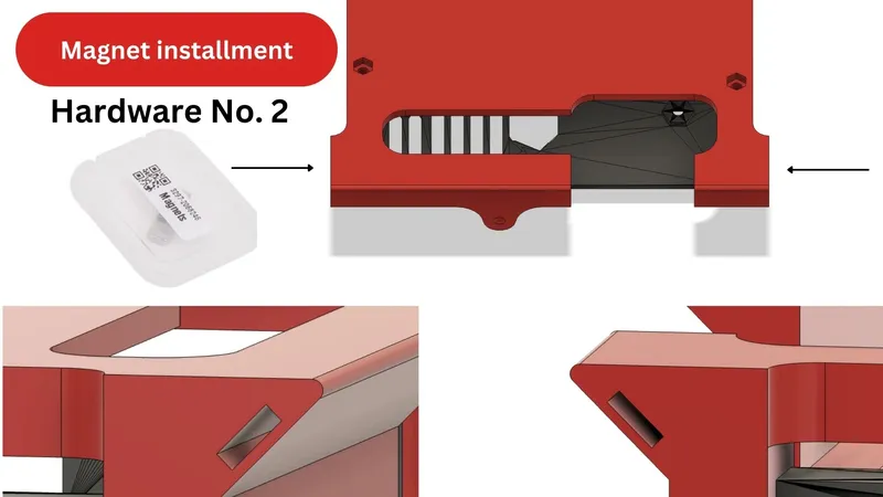
- 2x Magnet 20x6x2 PrusaShop
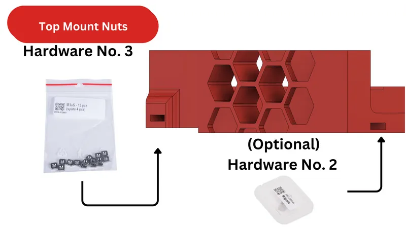
- 4x M3nS (Square nut) PrusaShop
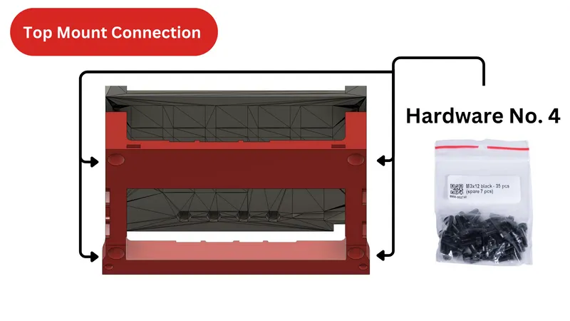
- 5x M3x12 black PrusaShop
- 5x M3n black Prusa Shop
- 2x M3x8 black Prusa Shop
Installation Process:
When all parts are acquired installation can beginn.
1
If not already done remove MMU2S from printer. Disconnect cables going from the printer to the MMU2S.
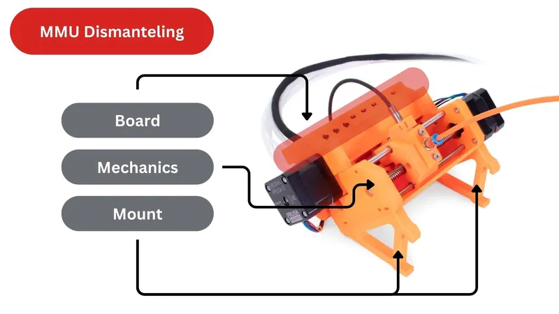
2
Separate MMU2s into the two main pieces (Board and mechanical parts). The board should stay in its printed part. It will still be needed. Afterwards remove the mount of the MMU2S which connects it to the printer frame. They won’t be needed anymore and can go in storage :)
3
Now you can begin preparing the Enclosure. If a handle was previously installed remove the old handle by unscrewing the two screws holding to the Enclosure.
Add the old Hardware to the new handle or add new Hardware.
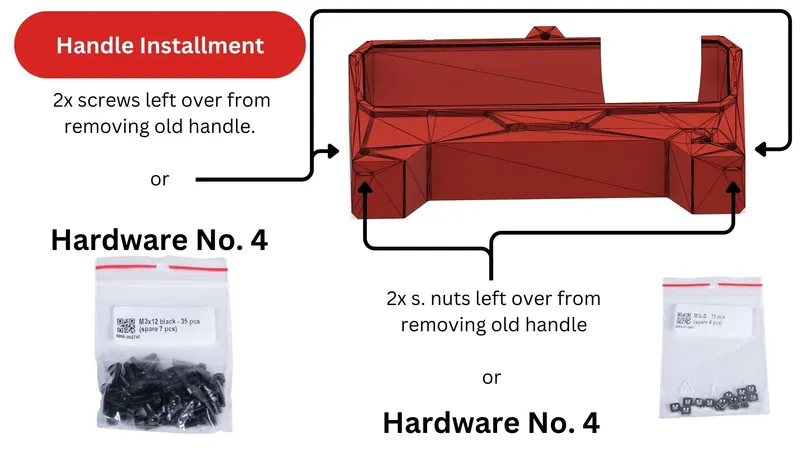
Mount the new handle on the left side of the printer. Due to the length of the MMU2S cable it can only be mounted on the left side of the Enclosure. If you desire to mount it on the right a longer cable is needed. The printed parts won’t need to be modified
4
Afterwards the Top plug on the Enclosure can be removed. Nylon rivets are easily removed with a pair of pincers. Go between rivet head and printed part and lift upwards. The Rivets can be used again if not damaged.
5
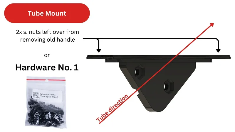
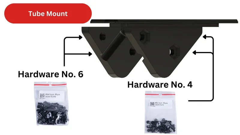
The New plug needs to be assembled in the final position. Prepare the plug with two nuts and place it through the cutout on top of the Enclosure. Make sure the direction the Bowden tube will face is the side where your MMU2S is located. Install the bigger part to the Enclosure using two rivets either old ones from the previous plug or new ones.
6
Then place the tube inside and screw both printed parts together. This will clamp the tube in place and secure it so make sure u have the appropriate length of tube inside and outside of the Enclosure so it reaches both MMU2S as well as the extruder in the lowest position.
Half of the work is done. Great :)
7
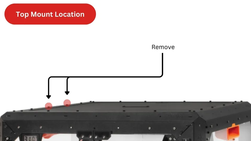
Now to the top mount. Unscrew the two middle screws from the top of the enclosure on the side you wish to mount your MMU2s.
8
Screw the mount to the mechanical unit of the MMU2S. The bottom of the mount includes holes that are big enough for a hex key. Then place it on top of the enclosure.
9
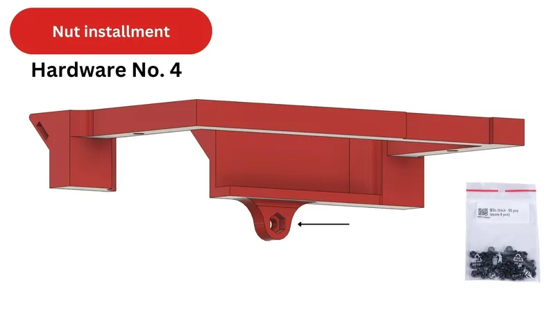
Slide the square nuts into the print on the two outside facing corners of the mount and fasten it down from the inside of the Enclosure. Additionally magnets can be added on the opposite side.
10
All that's left to do is mount the board on the side of the Enclosure for easy access to the buttons.
Insert the Magnets left and right into the print. If necessarry the left side has space to accommodated up to two magnets. 3 in total for the print.
11
Press a nut in the given slot.
(Only needs to be done if the board should be secured to the Enclosure with a screw. Recommended to only skip this step if 3 magnets were used in the previous step)
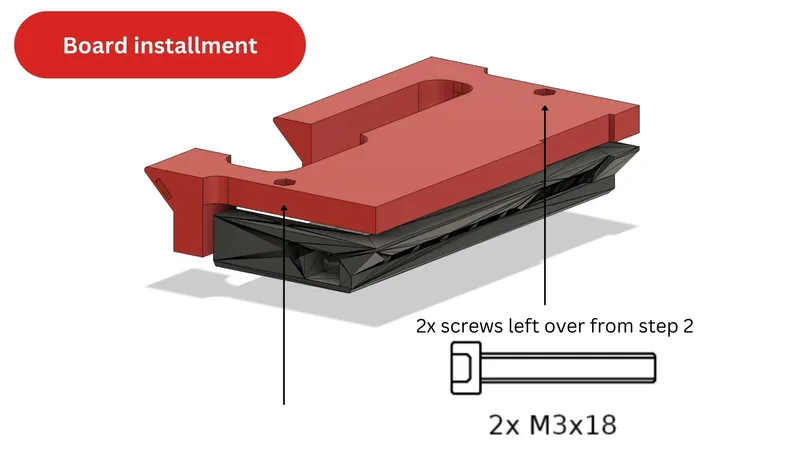
12
Fasten the printed part to the existing MMU part that holds the board.
13
Afterwards place it onto the side of the Enclosure. If step 11 was not done that was all. If the nut from step 11 was installed screw the side mount from the inside of the Enclosure onto it.
(picture; Hardware No. 6 + location)
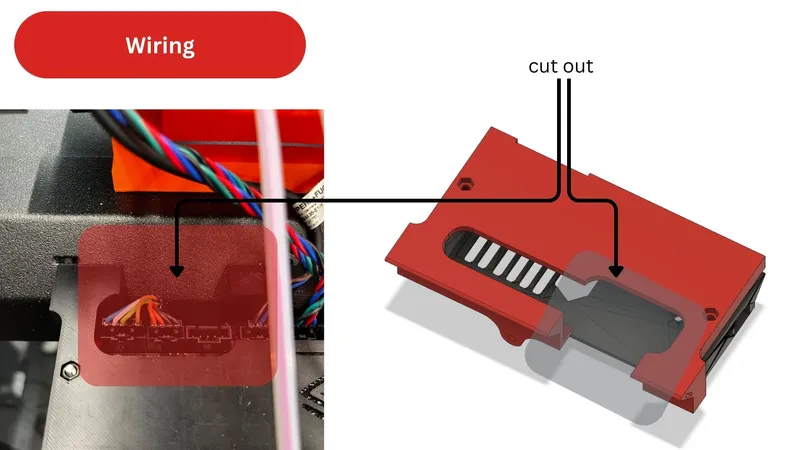
14
In the End the MMU2S cables can be feed through the handle. Using the cut out in the side mount feed them behind the side mount and plug them in. The other cables don’t need to be mounted differently. If they got unplugged just plug them back into the board. The location of the new mounts Is perfectly spaced to make full use of the given cable length.
Congrats after giving your MMU2S or MMU2 some filament you are ready to print :)
Happy printing.
Tags
Model origin
The author marked this model as their own original creation.