MK3s Auxiliary Fan Mount

Description
PDFThe popularity of auxiliary fans in enclosed printers like the Bambu X1 or Creality's K1 made me wonder of how I could implement something similar with my MK3s+ / Lack enclosed printer. I've included the step files for the duct and mount. There's room for some refinement or improvement in the mount and to allow others to design better or more efficient ducts.
I can't guarantee clearance with all forms of part cooling fan arrangements. Plenty of room for the factory setup, and it just gently touches the edge of the fan using the X2 delta P setup. Won't affect printing, as it only just contacts the fan when the hot end is at the far end of it's travel.
Goals:
- Require no permanent modification to the printer
- Allow for installation without removing the enclosure
- Move with the print head, allowing the air flow to be directed to the current layer.
Required hardware:
- M4 and M3 heat inserts ( 4mm length )
- M4 x 20 fasteners (x2)
- M3 x 8 fastener ( button head recommended )
- 5015 24v fan
- Rocker Switch for simple on or off
- (Optional) Potentiometer for pulse width control of fan ( recommended )
Recommended Material - ASA or ABS. Depending on your nozzle, it's recommended you print the bracket attachment legs solid.
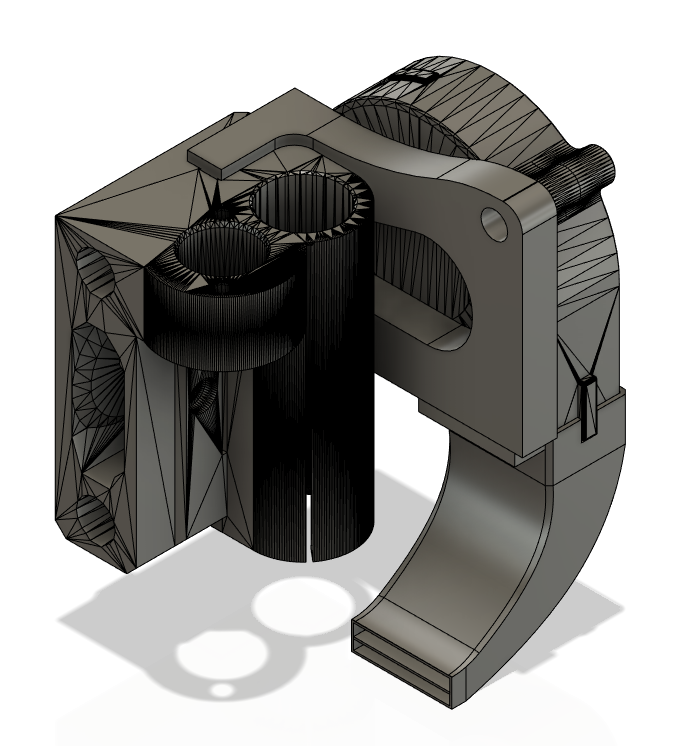
The mounting bracket was modeled directly off the MK3s+ part ‘P6’ and utilizes the two square holes found on the top and bottom of the part, just to the rear of the bearing rod. The arms give slightly, allowing you to bend them and snap into place.
The duct is intended to aim at the nozzle, roughly. At the distance it's mounted, the air should diffuse somewhat before it reaches the print, achieving the desired affect.
The potentiometer I modeled a controller housing for is this one here on Amazon. It features it's own on/off so you won't need a separate switch with this one - https://www.amazon.com/dp/B08PCW5F83?psc=1&ref=ppx_yo2ov_dt_b_product_details
I am still refining the potentiometer housing model - fitment may be a tad tight.
The switch I modeled a tiny housing for, is intended to be screwed to the enclosure - https://www.amazon.com/gp/product/B018FHB0H6/ref=ppx_yo_dt_b_search_asin_title?ie=UTF8&psc=1
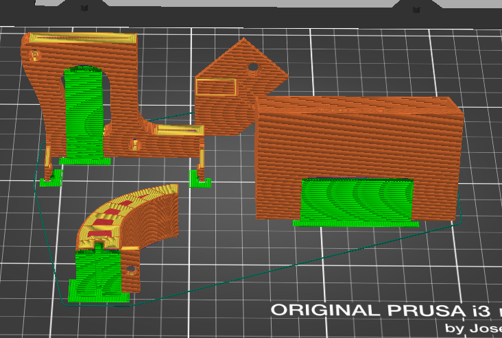
See plating picture for recommended supports. Only the fan opening of the duct needs support, don't support the duct interior
Install the heat inserts into the bracket - the two M4's mount the fan, the M3 mounts the duct. Assemble the entire unit before installing. A ball head allen wrench is very useful for securing the duct, having to reach past the duct itself to get to the screw.
For wiring, if using the potentiometer I linked, it's a simple power/ground in from the power supply and power/ground out to the fan. Silicone wiring is recommended. Make sure your connections are properly secured and shielded ( heat shrink! )
If opting for the all or nothing rocker switch, use the switch to interrupt the ground supply to the fan from the power supply and wire the power direct to the fan.
The assembly is then attached to the side of the bearing bracket, bending the legs slightly and then sliding the squared protrusions into place. It should ‘click’ in nicely and be fairly firm. A pocket flat head screwdriver can be helpful bending the leg over the bracket.
I've not yet performed any empirical testing of the performance improvements, just some informal stuff with long PLA prints where I wanted better control over edge curl. I recommend you don't activate the fan until your part cooling fan achieves it's full speed for your print, and if you opted for a potentiometer, match your fan speed with the controller. I'm also trying to work out an intake but I'm not totally happy with the one I have worked out right now. Will update if I produce something I like well enough to share.
Tags
Model origin
The author marked this model as their own original creation.


