Pinhole Camera

Pinhole camera, laser cut from black cardboard, screen out of tracing paper. Use in bright light, sunlight preferred
13
40
0
1048
updated June 27, 2023
Description
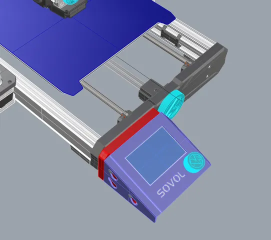
PDFThis pinhole camera is designed to be cut by laser cutter from black cardboard. The screen should be cut from tracing paper. The 3D file is supplied for illustrative purposes only (and because printabels forces you to upload a 3D file).
Cut both files “Pinhole camera 1” and “Pinhole camera 2” form black cardboard 300g/m². The cutting order should be as follows:
- Red lines should not be cut all the way through the cardboard. These lines will allow clean folding edges later. About 25% power compared to a complete cut through produced good results.
- Blue lines, cut through
- Cyan lines, cut through
Cut “Pinhole camera 3 (tracing paper)” by laser if you need about 35 screens. Should you need significantly less than 35 screen usage of scissors is advised. The resulting quadrat should be about 56 x 56 mm².
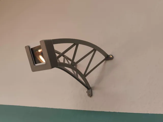
Please also refer to the fotos for the assembly
- Fold the large part from “Pinhole camera 1.svg”. The surface facing up on the laser cutter will be outside of the camera, so that the pre cut bending lines all face outward.
- The three small tonges on the one edge should be pushed into the three corresponding slots on the opposite side of this sheet from the outside in. This requires a tiny bit of force, so that the tonges will later stay in place. The result should be a rectangular tube.
- Bend down the three smaller tabs on the one end of this tube
- Close this end of the tube by bending the larger, quadratic tab down and inserting the little tong attached to it into the corresponding slot, again with a tiny bit of force.
- Push the “quadrat with a hole” part behind the quadratic tab. Avoid placing this part under the three smaller tabs from step 3.
- Bend the sides of the small stripe with the four holes upwards by about 30 to 45 degrees.
- For lack of a better description: Push this stripe through the opening as shown on the photo. The four holes are different appertures, so make sure that one of these holes is in front of the langer hole of the part from step 5.
- Bend the holder for the screen so that all four tongues go from the outside into the corresponding slots, hard to describe again, please refer to photos.
- Lay tracing paper screen into folded holder.
- Lay the quadratic frame on top of the screen
- bend the four tongues of the holder to the inside so that they hold the frame and thus the screen in position.
- Push the screen about half way into the rectangular tube with the screen facing the front. The two rounded tabs are the handles with which you may pull the screen back if needed to adjust the picture size later
- Point front a light source and look from the rear end onto the screen. Slide the stripe from step 7 to other hole sizes to adjust sharpness vs. brightness.
- Enjoy!
Tags
Model origin
The author marked this model as their own original creation.