Neptune 3 Pro X Gantry Light Bar Mod
Description
PDFPERFORM THIS MOD AT YOUR OWN RISK. This mod requires that you undo some of the manufacturer's cable management and add your own.
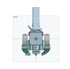
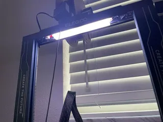
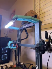
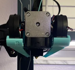
This model is a bracket to allow for the relocation of the Neptune 3 Pro light bar from the top of the frame to the rear of the X gantry. It mounts to the screws attached to the rear X axis mounting plate using the stock screws. You will need 3 M3x8 socket head screws and 3 M3 nuts to attach the bar to the gantry. The diffuser mod I posted a bit ago is featured in the photo for this mod, and can be found here:
https://www.printables.com/model/504223-neptune-3-pro-light-bar-diffuser
Note: If you decide to use the diffuser mod, you will need slightly longer screws to compensate for the thickness of the diffuser mounting bracket.
After installing this mod, I realized that moving the light bar to this location provides much better visibility of the nozzle in person, but the harsh light in this area wreaks havoc on webcams as it severely throws off the exposure, and dimming the light bar causes banding in the video feed due to the flicker introduced by lowering the voltage of the lights. If you plan to use a webcam to monitor your prints, this mod is not the best way to do so. I am working on a printed mod to allow for relocating the light bar to an angled mount at the top of the frame, about 150mm out from the front of the X gantry, to provide the best of both worlds for print visibility and video feed lighting.
When installing this mod, it is necessary to remove the cover on the rear of the left Z extrusion and pull the cable for the light bar down to where it comes out of the frame. The cover is press fit, just be careful not to crack it when pulling it out. Once the cable is free at the top of the channel, you'll have to separate the cable for the light bar connector from the filament run out sensor, which should peel back fairly easily, and then feed the cable between the slot cover and the channel. This was a little tricky just because the connector needs to twist to fit through the gap, but once it's through, lift the slot cover from the bottom to free the connector, finish separating the cables, and route the cable through the cable management clip that holds the ribbon cable for the hotend. I added an adhesive cable clip to the z lead screw plate to keep the cable from interfering with the Z axis lead screw. Make sure the cable has enough slack to lift the print head to maximum z height without putting strain on the cable or wrapping around the lead screw.
Tags
Model origin
The author marked this model as their own original creation.


