Z Anti Wobble - Ender 3 - Filament Pins Remix
Description
PDFZ Anti Wobble
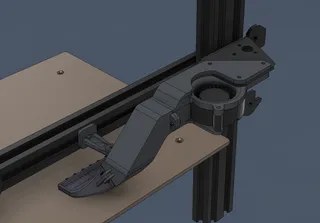
This is a remix of the awesome Z axis anti wobble design by Tekti that uses filament pins.
For 8mm lead screws.
Nuts - with 18mm or 16mm spaced mounting holes (check the 16mm stl file).
Not compatible with the stock bowden setup on the Ender
I couldn't acquire the 32 metal pins required for the original design and I modified it so you can use 1.75mm filament as pins instead. If you are able to source the pins please make sure to check out his original design.
I used to run an Oldham coupler, but this design provides less friction and less backlash.
The rails which are 90 degrees to the direction of rotation and the weight of the X gantry constrain the balls in place and transfer the motion smoothly resulting in consistent Z layers.
It might help securing the Z lead screw at the top of the frame to transfer the motion smoothly into the anti wobble coupler. Don't do so if your screw is severely misaligned or bent. Fix that issue first.
Hardware:
-4mm steel balls x8 (from two 628 bearings)
-6mm x 3mm magnets x12 (or thinner ones that can be stacked)
-Button Head Screws - M3 x 8mm x4
-Some 1.75mm filament
-Silicone grease (or plastic friendly grease)
Print settings:
-0.2mm layer height
-3 perimeters
-5 top, 4 bottom layers
-20% infill
Assembly:
-Take a strip of filament and a flush cutter and insert the filament into the small side holes for the Top and Bottom parts.
-Insert the pins on only one side of the Middle part.
-Insert the magnets in the middle of the block. Triple check that the polarity of the magnets matches.
-Finish inserting the pins on the other side.
-Insert the magnets on the Top and Bottom parts. Check that the magnet polarity matches and they attract eachother. The parts can be put together in only one orientation which is labeled on the side. Make sure the line and the letters are all aligned.
-For extra security you can add a dab of superglue on the outer sides of the filament pins.
-Add silicon grease to the steel balls to minimize wear and finish the assembly.
Installation:
-Unscrew the Z nut from the X gantry.
-Disconnect the Z lead screw from the bottom motor coupler
-Slide the Z nut down and remove it from the printer.
-Screw the Z nut and the Bottom part together (Z nut sits below)
-Insert the Top part on the lead screw from the bottom and attach it to the X gantry. Make sure that the side labels of the parts are in a visible place.
-Insert the Middle and Bottom parts
-Reattach the Z lead screw to the motor coupler
-Align the parts together so they match the lines/labels on the side.
Enjoy!
Tags
Model origin
The author remixed this model.


