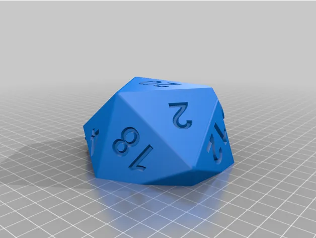
D20 Puzzle Di Holder MarkII


Description
PDFD20 Dice Case - Puzzle Box - Mark II
Video showing how it works.
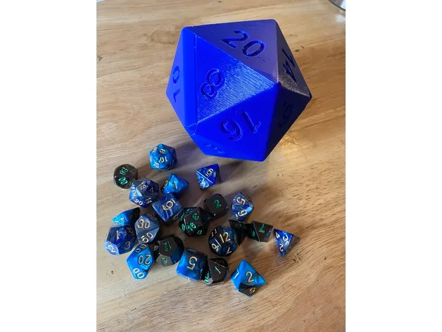
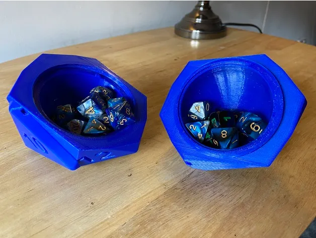
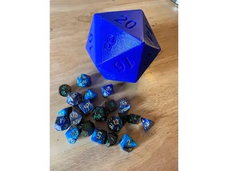
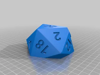
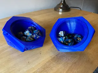
This is a D20 shaped puzzle box. You have to rotate 2 faces in order to unlock it, then you can unscrew it and get to the inside.
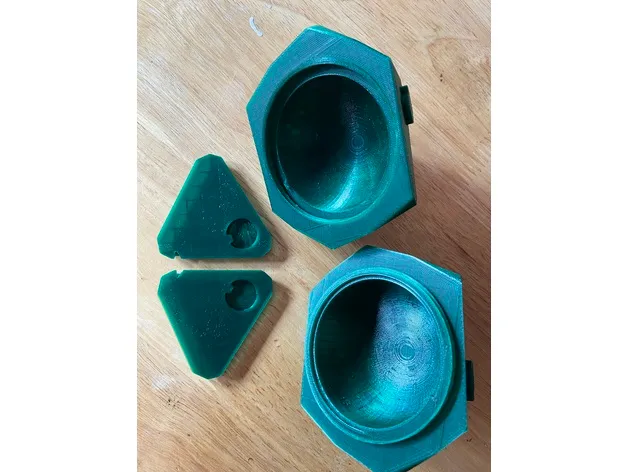
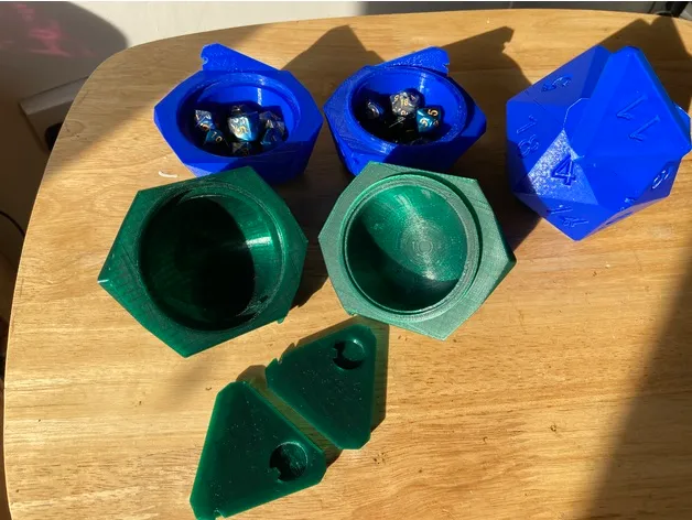
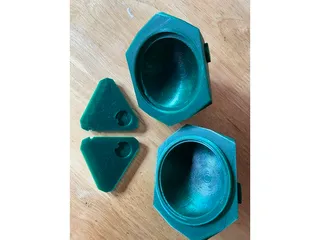
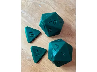
This print consists of 4 pieces:
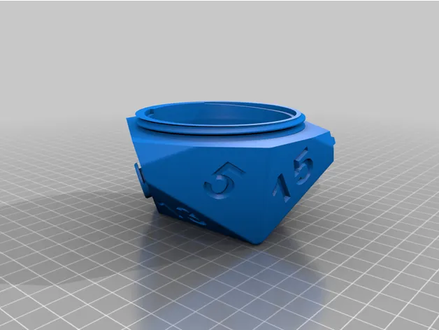
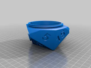
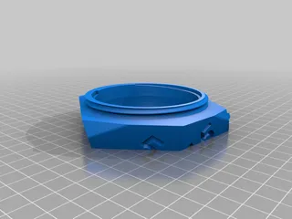
⁃ d20 Half 20 - the 1/2 with the 20 at the bottom
⁃ d20 Half 1 - the 1/2 with the 1 at the bottom
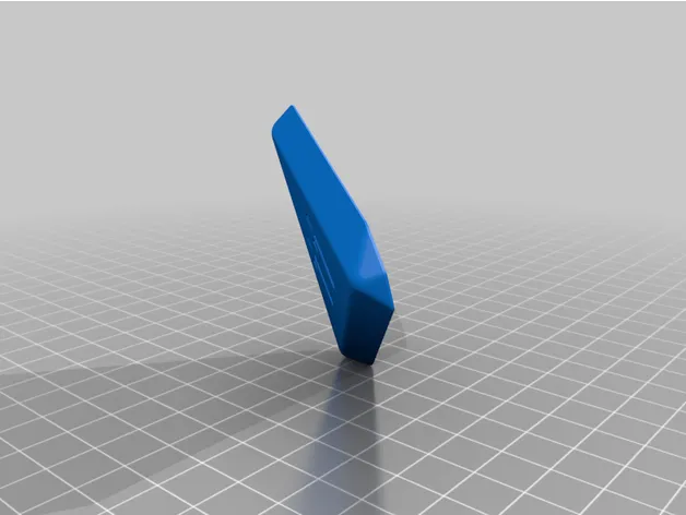
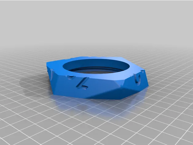
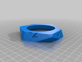
⁃ d20 Lock 11 - the locking side with 11
⁃ d20 Lock 10 - the locking side with the 10
The d20 Lock 10 goes with the 20 half, and the d20 Lock 11 goes with the 1 half. Very important to get this right.
I recommend the following print settings:
⁃ Layer height: 0.25mm or 0.20 mm
⁃ Infill 10%
⁃ Support Material on bed only for dice Halves
⁃ No support material is required for the 10 and 11 locking sides
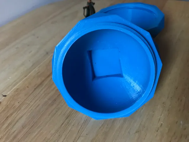
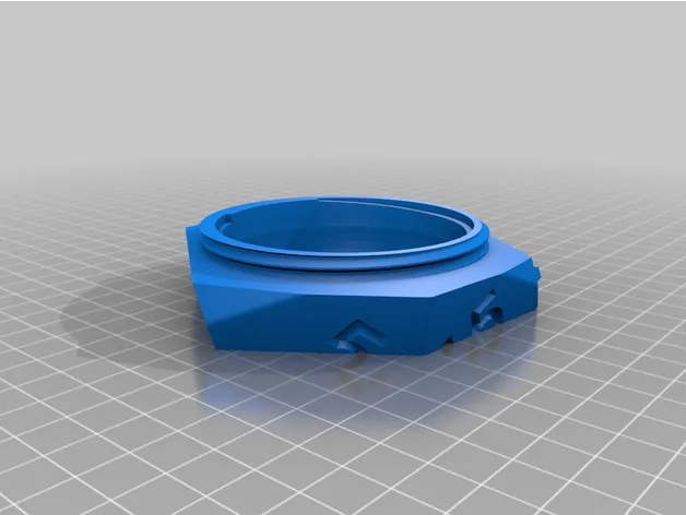
When printing the two halves, ensure the number 1 and number 20 (respectively) are on the bed surface and the middle screw section is at the top. When you import the 1 half, it will look like it’s on the bed but double-check that it is fully on the bed.
When printing the 10 and 11 locks, print them with the numbers facing up, no support material is needed.
I was never a huge believer in the different qualities of different filaments. I always figured plastic was plastic, and cheaper was just as good as the more expensive stuff. Until this project.
I printed 2x of these dice with one brand of filament at 0.25mm, and the two halves screwed together quite easily, and it comes apart quite easily, as expected. I then switched filament so I could print it in a different colour (which happened to be a different brand of filament), and I can’t get the two halves together at all. And they are nearly impossible to unscrew. So, I lowered my layer height to 0.20mm and reprinted. This one works better, but still, not nearly as smoothly as the first filament I used at 0.25mm.
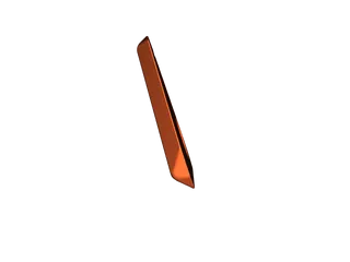
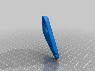
So, I have included in the project 2 additional STL files of just the screw section, plus about 15mm on either side. This way you can test if they’ll screw together nicely with the filament you have without having to spend 4 - 6 hours printing each half only to find out it doesn’t work. (Like I did!)
Assembly
Once all four pieces are printed, start the assembly by screwing the two halves together, and taking them apart several times until they screw together and come apart smoothly. You may need to work them back and forth, slowly getting tighter and tighter as you go. All of the edges should line up perfectly when fully screwed together, and the crack between them should nearly disappear.
Now, completely separate the two halves.
Look at the underside of the 10 and 11 locking sides, and notice the notch in one corner of each. Take a pen knife and trim out the edge of this notch so there isn’t any overhang on the bottom edge. Also check the round hole is clean and has smooth edges, and that the posts on the 2 halves area also clean and any burrs left by the supports are removed.
Line up the hole in the 10 locking side onto the circle post on the 20 half. Notice that the 10 is a little bit (approx. 15 degrees) to the right of centre. Push the two pieces together, then rotate the 10 as far as it will go counter-clockwise. It should go to the point where the right edge of the 10 piece is parallel with the top edge of the 20 half. Or near enough.
The 11 locking side will clip onto the 1 half of the di, and initially sits about 15 degrees left of centre. Once the two pieces are together, rotate the 11 locking side all the way clockwise, until it stops. The left edge of the 11 should almost be parallel to the top of the 1 half.
Now, screw the two halves together.
Rotate the 10 clockwise to lock, and the 11 counter-clockwise to lock.
Tags
Model origin
The author marked this model as their own original creation.