Grid Clock v2 REMIX - Fully Enclosed Version with Adrunio Nano or NodeMCU options

Description
PDFThis is a remix of Parallyze's Awesome Grid Clock V2, and uses the "GCv2_Grid_Base_v1.stl" and "GCv2_Grid_v1.stl" parts from the original model. All the clock dimensions, aside from thickness are the same as the original design. I recommend that you use the instructions from the original for the basic assembly and electronics design, which will serve you better than anything I could write up for this remix.
The idea behind this remix was originally to make the top part fully printable (no filter paper or screens required). After making the top part separate, I thought, why not just make it fully enclosed? So a simple change spiraled out of control, and now it is fully enclosed, with mounting points for the electronics, an optional fuse holder, LDR holder, and wall mounting holes and wall mounting pegs that can use 3M command strips.
This uses some additional hardware (additional to the hardware needed for the original Grid Clock V2)
- M3x10mm screws to hold the back plates on (16 to 24 depending on the size of the clock)
- M3x16mm screws (optional - 2 needed for the fuse holder)
- M3 x 8mm screw to secure the Arduino Nano (if using that design).
- M3 locknuts (optional - 2 needed for the fuse holder)
- DC panel jack (looks similar to Amazon Item B077YB75N3 - see note below)
- Standard Auto Fuse if using the fuse holder option, you can also buy automotive single fuse holders to wire in if you do not wish to use a printed fuse holder like I did.
- LDR (I used one I had around - the hole for the LDR is about 7.6mm dia)
(note about the DC jack connectors - the 5.5mm jacks come in two sizes (5.5x2.1mm and 5.5x2.5mm), so it would be best to find out what jack your power supply will use and just get that type. Most of mine are 5.5x2.1mm jacks. The hole for the DC jack is 11.98mm in diameter and has flats on the top and bottom)
If you are using a DS3231 RTC module and will power it with 5V please see the note below in the post-printing section, and this link for an important safety consideration:(Thanks again to Parallyze for point that out to me!)
https://www.onetransistor.eu/2019/07/zs042-ds3231-battery-charging-circuit.html
Thanks and acknowledgements:
*Parallyze for the Grid Clock V2 design and code this is remixed from, as well as his support for some of my questions regarding the code. This design is based off his model and uses his code.(BIG THANKS!): https://cults3d.com/en/3d-model/home/grid-clock-v2
- The Arduino Nano mount is remixed fromAlpoHassinen's Arduino Nano Holder:
https://www.thingiverse.com/thing:2635159
- The fuse holder version uses the parts fromErik Cederberg's design posted on Thingiverse bysk8rjess (please read the comments for that thing to decide if you want to use this or not - it was recommended to print in high temp fire retardant filament).
https://www.thingiverse.com/thing:1787609
https://www.youmagine.com/designs/stackable-fuseholder
=====================================================================
Print List:
=====================================================================
For a SMALL clock:
=====================================================================
Print 2 each of these:
Clock_Remix-NEW-7J-SIDE-CLIP-TOP.stl
Clock_Remix-NEW-7J-SIDE-CLIP-BOTTOM.stl
Clock_Remix-NEW-7F-BU-BUTTON-CLIP.stl
Clock_Remix-NEW-7G-BU-COMMAND-STRIP-WALL-MOUNT.stl (optional)
You will also need 2 "RL-TOP"s which are composed of the following (see printing notes below for these):
Clock_Remix-NEW-7L-RL-TOP-GRID.stl
Clock_Remix-NEW-7L-RL-TOP-INSERTS-SUPPORT.stl
Clock_Remix-NEW-7L-RL-TOP-SCREENS.stl
These will need to be downloaded from the Parallyze's original design and printed (2 are needed)
"GCv2_Grid_Base_v1.stl" and "GCv2_Grid_v1.stl"
Print one of these:
Clock_Remix-NEW-7K-R-BASE-TRONICS-ARDUNIO-NANO.stl
-or-
Clock_Remix-NEW-7K-R-BASE-TRONICS-NODE-MCU.stl
Clock_Remix-NEW-6S-M-BASE-NO-WALLHOOK.stl
-or-
Clock_Remix-NEW-6S-M-BASE-WALLHOOK.stl
Clock_Remix-NEW-6S-L-BASE.stl
Clock_Remix-NEW-7K-R-SIDE-SHELL.stl
Clock_Remix-NEW-7K-L-SIDE-SHELL.stl
=====================================================================
For a LARGE clock:
=====================================================================
Print everything listed above. Additionally, print one of each of the following:
This will need to be downloaded from the Parallyze's original design and printed (1 more is needed):
"GCv2_Grid_Base_v1.stl" and "GCv2_Grid_v1.stl"
The rest of the parts are here:
Clock_Remix-NEW-6S-M-BASE-NO-WALLHOOK.stl
-or-
Clock_Remix-NEW-6S-M-BASE-WALLHOOK.stl
Clock_Remix-NEW-7K-M-SIDE-SHELL.stl
You will also need an additional "M-TOP" which are composed of the following (see printing notes below for these):
Clock_Remix-NEW-7L-CENTER-TOP-GRID.stl
Clock_Remix-NEW-7L-CENTER-TOP-INSERTS-SUPPORT.stl
Clock_Remix-NEW-7L-CENTER-TOP-SCREENS.stl
=====================================================================
The STEP files are included for easy remixing.
If you find these models useful, please post a like or a comment with some pics of your prints.
You can find the other things I'm working on at my blog here. You can also follow me here on Printables to see what new stuff I post. Thanks for looking!
Update 10/25/2021 - Fixed the following files which were corrupted (Thanks to thefckinglizardking for letting me know!):
Clock_Remix-NEW-7K-M-SIDE-SHELL.stl
Clock_Remix-NEW-7J-SIDE-CLIP-BOTTOM.stl
Notes:
Use your best judgement on the type of fuseholder to use with this. It was recommended to print the fuseholder in high temp fire retardant filament. You can also buy a single automotive fuse holder and wire that in, if you do not wish to use a printed fuse holder. I am not an electronics expert, I did the best I could with the design and the info below (and have been using my clock for a few years now). As always, use your best judgement on electronics design and components selection and make this at your own risk.
Printing and Post-Printing Suggestions:
UPDATE 4/20/2024 - To simplify things, I uploaded a 3MF with all the parts, including the screens, which are set up for printing. The 3MF is not test printed, but it should work, and feedback is welcome. I also slightly changed the screen files to allow for easier printing.
Assembly
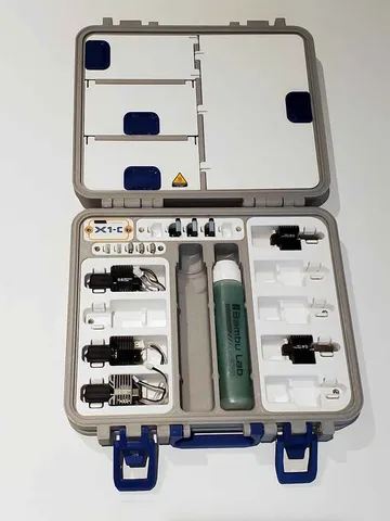
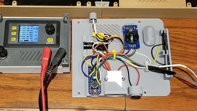
The first thing I did was follow the instructions for the setup and wiring of the LEDs from the original design (http://www.cikic.de/3d_projects/documentation/GridClock_v2/index.html). I also should add that I am not an electronics expert, merely a hobbyist so please do your own research and most of all, safety first. I set my clock up the same from the wiring and electronics standpoint, as the original instructions from Paralyzes' thing, but I did add the fuse and a capacitor as well. The fuse is inline with the positive power input as shown in the pics. I used a printed fuseholder, but you can also use an off the shelf fuse holder, so please use your best judgement on that component and all others used. The capacitor was over the positive and ground inputs (but it is a 1000µF 25V polarized electrolytic capacitor so polarity maters on this part). There is also a 2MOhm LDR which the original firmware supports, and works really well when the values are set up correctly for it.
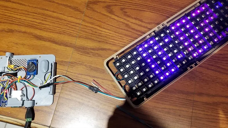
Note that in my pics, you will notice that I initially installed the LED's rotated 180° from where they needed to be. In other words, the pigtail from the LEDs (where they will connect, is actually at the bottom left if looking at the clock from the front.
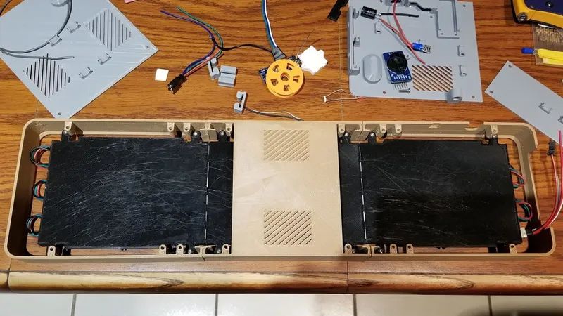
Once the LEDs are assembled and soldered according to the design, they should be attached to the back plates and the front grid separators should be clipped into place.
The LEDs will first be installed into the parts that form the left, middle and front sides. Use M3x10mm screws (4 per module) to install the LEDs into the side frames.
While assembling the LEDs into the side frames, you can also clip them together using the top (smaller) and bottom side clips. These should be snug, but you can also glue them in place. Try to get he frames aligned and as tightly together as possible here since the LED frame helps to bring the sides together and hold them in position.
To assemble the electronics base, follow the wiring scheme on the original Grid Clock V2 (http://www.cikic.de/3d_projects/documentation/GridClock_v2/index.html).
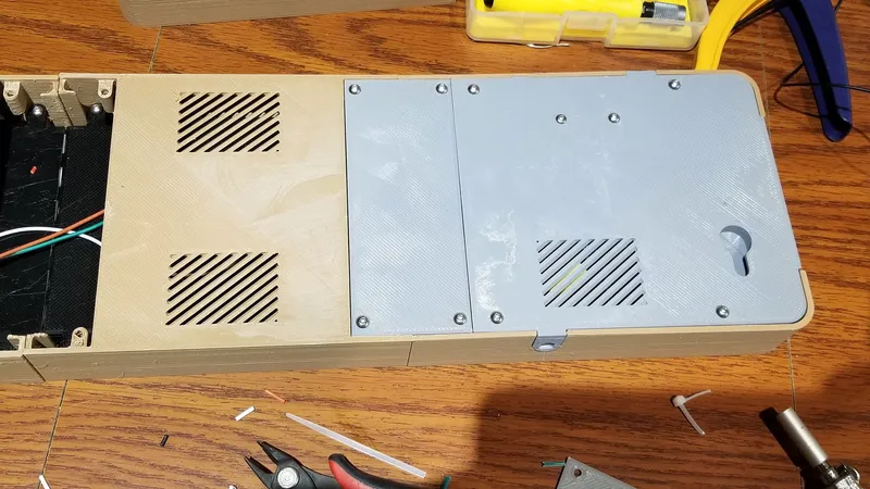
I used M3x16mm bolts and M3 locknuts to secure the fuse holder, and I used Gorilla Super Glue Gel to glue the DC Panel jack in place (I recommend gluing it after all the connections are soldered on it and tested). The DC panel jack has 3 pins and I only used 2 (center positive and edge negative). I also glued in the RTC module since I busted off most of the pegs (though I had intended on melting the pegs to hold it in). A small M3x6 or 8mm screw was used to secure the Arduino. If using the NodeMCU, it has mounting pegs and I did not really finalize if those would be best melted in or maybe just a dab of hot glue to hold it would work. I used some double sided foam tape to secure the capacitor since it was sort'a an afterthought.
IMPORTANT NOTE REGARDING THE DS3231 RTC MODULE
Thanks to Parallyze for pointing this out to me, and it's important so I thought it would be a good idea to post some info here as well.
If you are using the DS3231 RTC module, there is an issue with the battery charging circuit. The long and short of it is that if you use a non-rechargeable CR2032 like I did, you will need to disable the battery charging circuit on the DS3231 module (I was not even aware it did that until it was pointed out). And if you use a rechargeable lithium coin cell you basically will need to provide the DS3231 with 3.3V power instead of 5V as I did, otherwise the battery may be overcharged. That is a simplification, so see the link which explains the issue:
https://www.onetransistor.eu/2019/07/zs042-ds3231-battery-charging-circuit.html
Again, since I am using a non-rechargeable CR2032 3V cell, I simply removed the resistor shown below to disable the charge function.
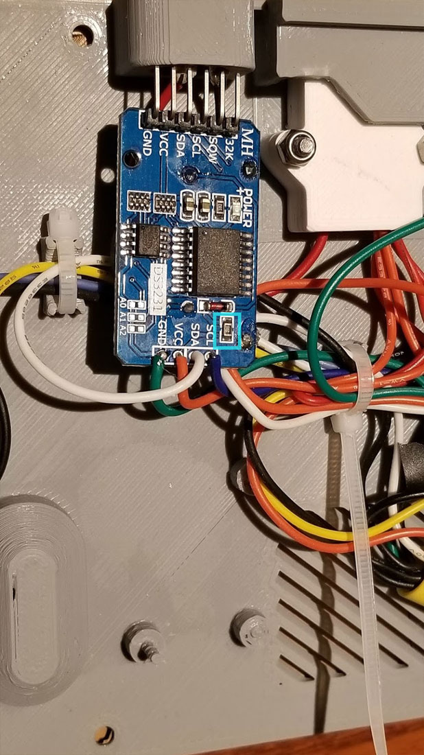
DS3231 with the resistor I removed highlighted
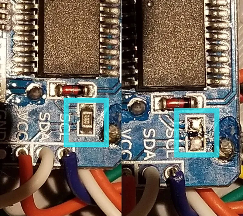
DS3231 before and after removing the resistor which connects the battery charging circuit to VCC (5V in my case).
The only changes I made to the electronics from the examples provided with the original design were:
- I added a 2A fuse in series with the positive power, connected directly off the power connector.
- I added a 1000µF 25V electrolytic capacitor on the power in line, across positive and ground. Electrolytic capacitors have a stripe which shows which leg goes to negative/ground and connecting them the wrong will will cause them to blow.
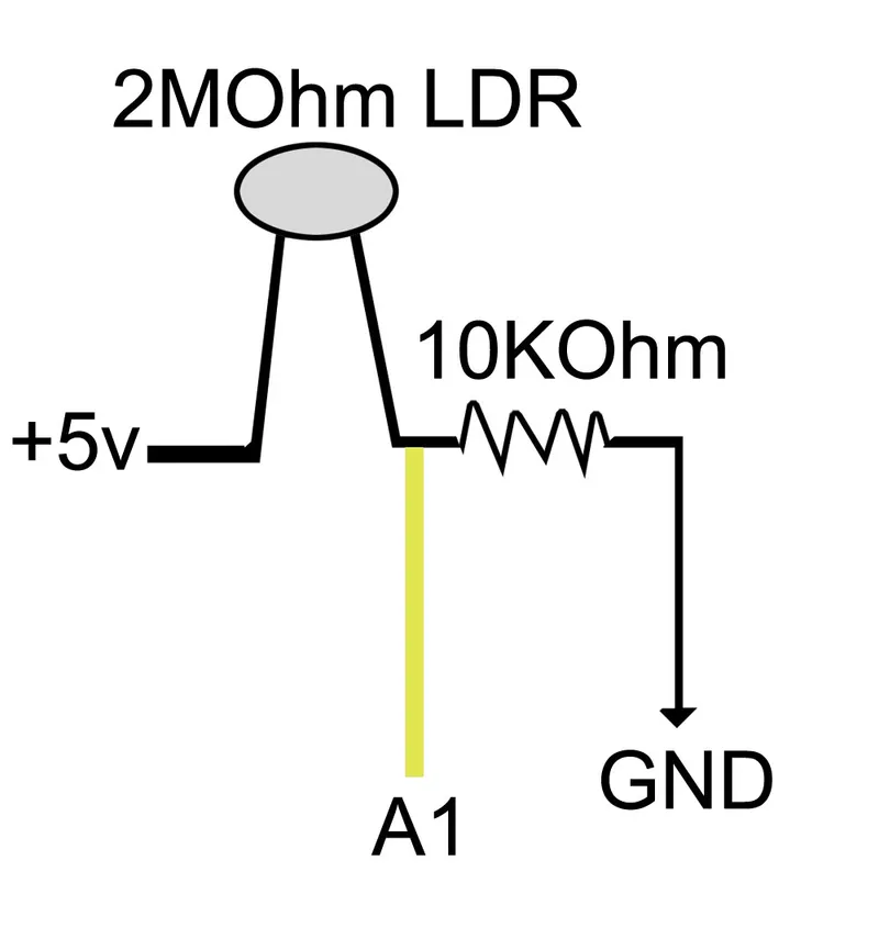
- I have an LDR which connects to the Arduino on pin A1 (yellow wire in the pic) and there is a 10KOhm resistor forming a voltage divider like this:
Before I attached the bases to the side frames I gave it a test and it passed, except I realized that I had to flip the LEDs at that point. Hopefully you won't do the same, just make sure the tail from the LED's is in the lower left corner and it should be good.
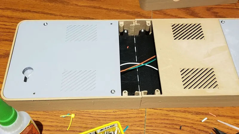
Then I just connected the wires and used the wire management clips with small zip ties (need the tiny ones), to button down the wires a bit. Then I closed the case back up using M3x10mm screws. The only thing to watch for is that the wall hooks face up and the fuse and power connectors are down.
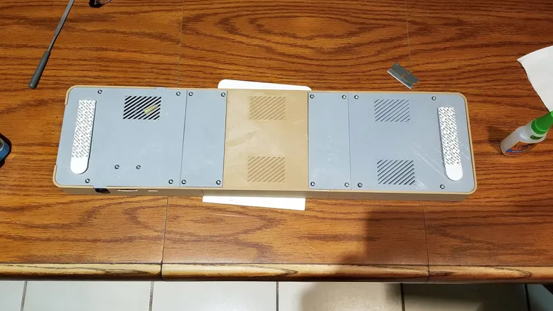
Lastly I flipped the clock over and glued in the front screen covers. These required a bit of help so I first ran a bead of Gorilla Super Glue Gel around the edges and then set the screens in place, wiping any excess of and then weighed it down with several large Juniper and Cisco Certification books which made themselves more useful to me than they have been in years. I glued the screens one at a time, and let them set for a good hour before moving on. Aside from printing this was the most time consuming part of the build.
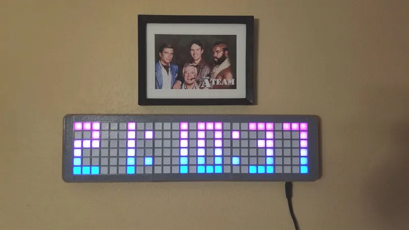
You can also toggle the overlayMode using the buttons (3 sec press on button A) which creates a gradient effect that cycles over the numbers slowly - it is a really cool effect!
Sorry no pics of the last step, but you can have this one:
Wall Mounting Hangers
I almost forgot about the wall mounts... They are just held to the wall using 3M command strips (large size). I stuck them to the clock first with a bit of foam tape to just hold them, and then mounted the clock (with the wall hangers attached) using a level. Once it was aligned, I just pressed down to stick the hangers, removed the clock to make sure the hangers were stuck, and then re-mounted the clock.
Additional Tips on the Electronics and Code:
If using an LDR, you will need to determine the settings to use in the code. I won't get into that here since this is long enough, but you can use the code here (https://playground.arduino.cc/Learning/PhotoResistor/) and an appropriate resistor for your LDR (I used a 10KOhm for mine and IIRC it was a 2MOhm LDR). I recalled that I had to adjust the values to a scale of 0 to 1023 to get the values to use in the code. I ended up using the following in the code:
// Using a LDR and 10K resistor, total dark = 70, dark room = 170, Light mid = 700, light full = 860
byte upperLimitLDR = 180;
byte lowerLimitLDR = 74;
byte minBrightness = 40;
EDIT: All this setup for the LDR is not necessary since you can just hook up the serial monitor and get appropriate values by hanging the clock on the wall and turning on or off the lights. My calculated values were close enough, but based on the serial monitor, with lights off it was 40 and on it was 88. Use 57600 baud on the serial monitor.
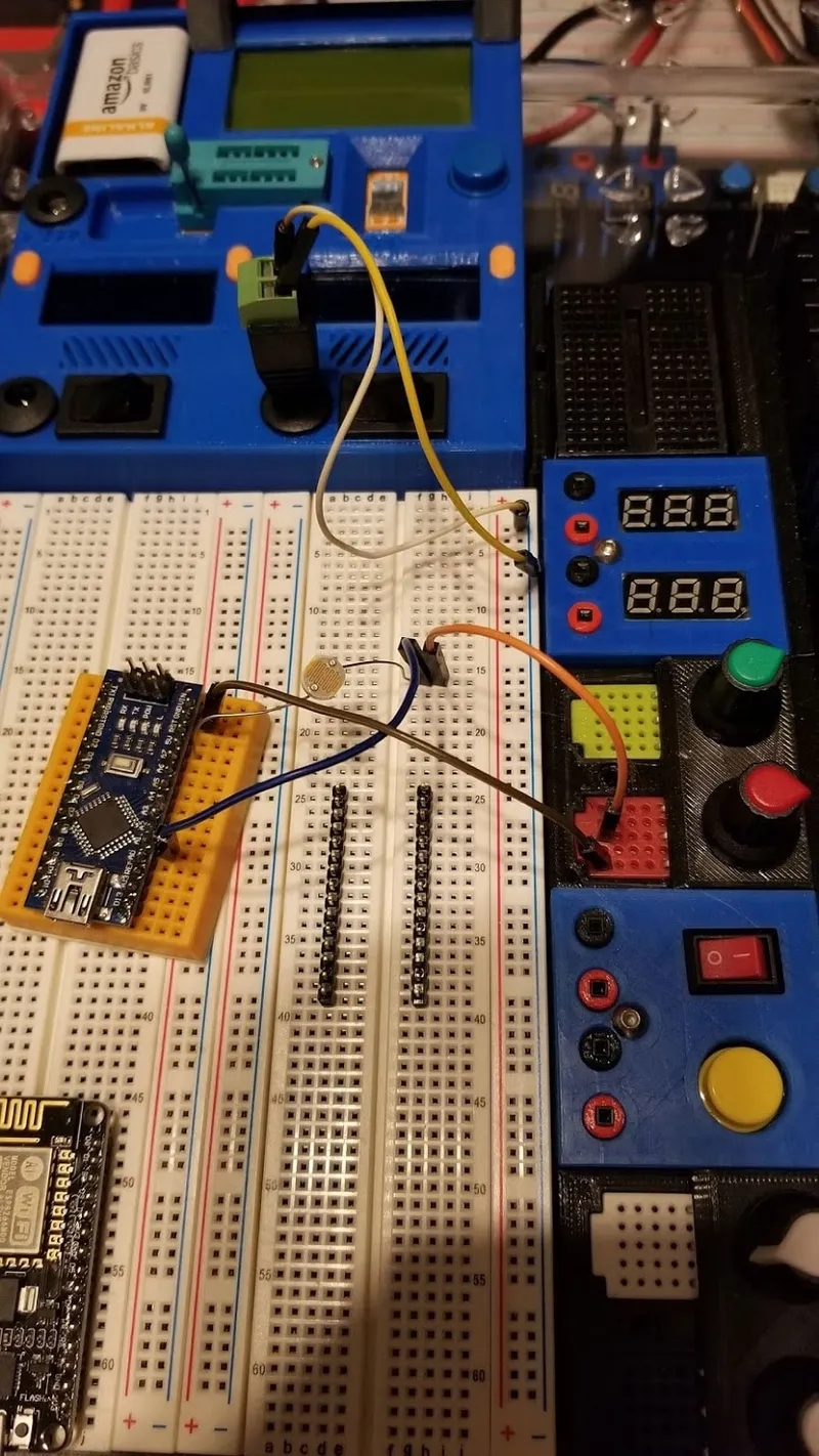
Testing resistor values for the LDR, and then finding the correct values to use in the code for lthe ow and high limits in the room the clock was going in.
I additionally added a 25V 1000µF electrolytic capacitor between the positive and negative power lines.
I increased the power a bit from the stock configuration (using 900mA which looks plenty bright).
I also added an option to change the display to show the leading zero between the hours of midnight to 10am when in 24 hour mode. Sorry I don't have any screen caps of this part since it was done later.
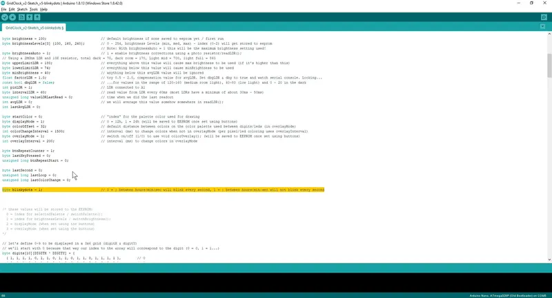
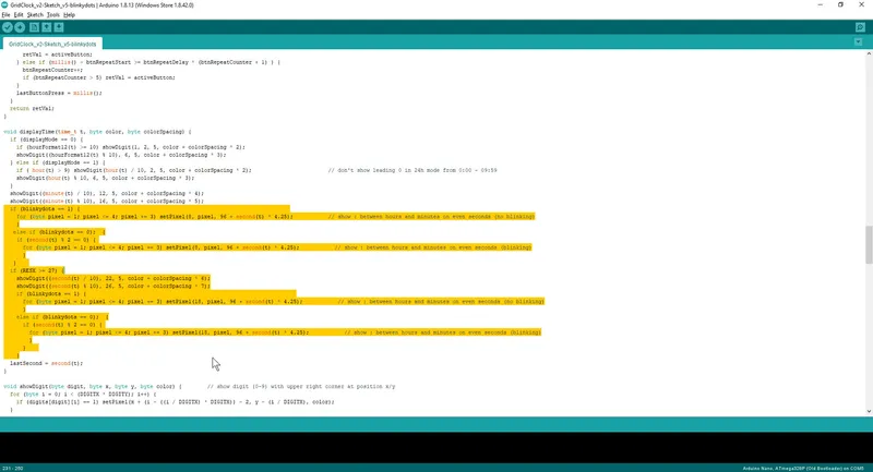
Finally, I modified the code just a bit to allow the option of toggling between blinking and non-blinking :'s between the HH:MM:SS. Since my clock is sometimes at eye level I wanted them non-blinking. To do that I added a variable called "blinkydots" and changed the following in the code (right click > view image to expand it):
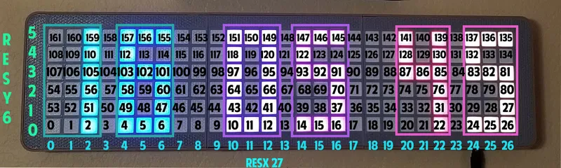
 And lastly (really), here is just an image I put together to help me understand the mapping of the LED's in the grid clock.
Category: Electronics
Tags
Model origin
The author remixed this model. Imported from Thingiverse.


Differences of the remix compared to the original
This uses some parts from the original, and adds a new frame and printed screens.