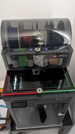
BambuLab AMS Riser with LEDs
Makes
Comments
Thank you for the model, I made it, and I like it. However, the creation went not as smooth as I had hoped for.
What I did not like:
First print failed because the slicer tried to print the overhangs on the side pieces from front to back, hence wanted to bridge 20 cm, which obviously failed. Not sure if this is an issue with the model or my printer settings?
Slicer told me that somewhere in the step file there were 8 non-manifold edges.
The connection between the side pieces, and the middle one were too tight for me. Maybe it was because I printed in PLA, but I was unable to click the pieces together. I ended up filing away the knobs to some degree until it fit.
While trying to connect sides and middle, the walls opposite the connections broke off. Without a round corner on the inside the wall was relatively easy to snip off.
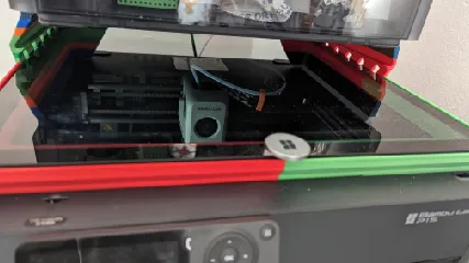
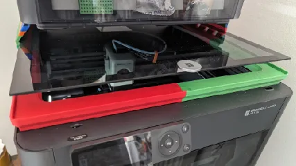
I’m not sure if the sizes are 100% on point. The TPU feet seem a bit oversized for the side pieces; there is a small bulge. The size of the AMS seems not exactly equal to the LED frame, but it fits overall. Hence not a real issue, especially if you do not plan to move the AMS every day. :-)
What I like:
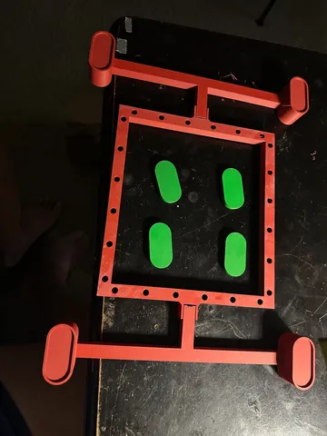
I like that the model comes with separate feet that can be printed from a soft material to protect the printer’s glass.
I like the idea to embed the switch in one of the feet.
I like the idea of using the AMS as a power source; that way the light can be switched with the printer.
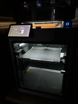
After all, it was a relatively easy small project and eventually I can see something inside the printer.
Future plan:
I am thinking about adding some more electronics to be able to switch the light on and off via browser. That way I could keep the Light off when I am away and only when checking a print in BambuLab’s mobile app, I could enable the light. (edited)
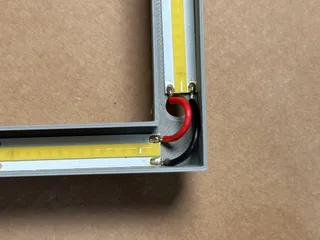
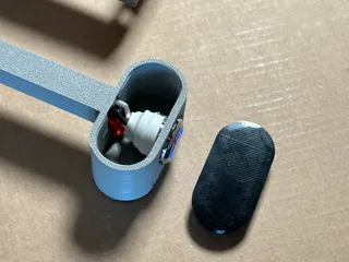
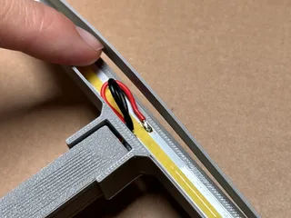
@dietrich Turned out nice and clean! I printed mine in the PACF that shipped with my x1c so there will probably be some tolerance issues between that and PLA. I included the step file Incase you need to make changes to fit etc. Glad you liked it and it's working nicely.
Different materials might explain the fit.
Maybe I have to reprint parts anyway to fit the electronics to switch via browser. I checked and the space in the remaining two feet is very limited to fit a step down module for the power (24v to 5V) and a esp8266 module for controlling the light. Right now I am thinking even to couple it with the status of the internal LED, which status can be found in the MQTT published by the printer itself.
Let’s see…
@T3CHKOMMIE
I love your design for the AMS riser with LED lights. I purchased the LED strip, switch, and a power supply to run both because I do not want to strip or solder wiring or tap into the AMS for power. I then printed everything and quickly found that power connectors for the switch (or power supply) will fit in the LED frame. Any chance you could make one that would? I would pay you. Thanks.
Thanks for posting the wire colors, I had done yellow and black and got 24v, but it didn't work when turning on printer. Yellow positive and red negative was the ticket. When looking at back of the ams, yellow is top left, red is top center for anyone that needs to know. (edited)
It was too small for me, too. By about 6-7mm in each direction. I'm making a remix with the correct dimensions, and will post it when it is finished.
@Sluggles I think I've heard the Kickstarter version of the AMS is a little different size wise. Should be bang on for the combo ams. If you print something shrinky like abs you might need to scale. 6-7 mm is WAY off tho. I cadded this part with less than 0.5mm tolerances. Shouldn't be anything like that far off. Make sure your legs are fully seated and connected.
Design is awesome. For my Kickstarter version of the AMS I had to scale everything up by 104% to align with the feet. Otherwise it's working great.
@Xnit_249247 thanks for the comment! It's a tight fit for the x1cc too. Thanks for the tip! (edited)
Love your design, but I don’t think I have the expertise to replicate that wiring.. so I just ran an LED strip through it and out the back. Had to cut a little in the top part of the right leg, but made it work. Thank you.
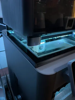
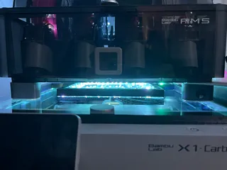

@ReeeTheWizard thanks for posting the make, glad the strip fit! :)
This is an awesome idea. I love embedding the power button into the feet like that! Such a clean look. I'm actually interested in embedding a power button in the other front facing foot as well, to control Bento Box fans. Is that a mod you could make and post, or would you be willing to post the source file so I can modify the Left Riser to add a hole for another button? I might also emboss a label for each power button onto the housing, denoting it's function: Light & Filter
@Mancolt look at the pin out on the wiki. Use your uncut end. The use continuity to figure out what striped end is your ground. Then plug it in and validate you have the right 2 pins. Ground doesn't cary volts. You'll only know you found it when you find both 24 and ground on your meter.
@T3CHKOMMIE that did it! Mine were the same as yours, red was ground and yellow 24v. As you said, checked continuity using that diagram and confirmed ground color. Then used black multimeter lead to the ground and red lead to yellow wire, changed my multimeter to 200v (pretty sure that's what worked) vs 20v and I saw 24v. Thanks again for your patience and explanations. Looking forward to adding a remix of my own.
Hello, I want to print it, because it'a abeautiful concept. But I have a question: For printing the right support, If you don't use supports ( inside the square tube), bambu studio is not happy ( and I andestand why ). But if a put supports, HOW can you pass the cable inside it? So, How did you print it?
@DuFer_158173 the Bambu studio default settings for overhangs are aggressive. My slicer complains about needing supports. You shouldn't need supports and they will be impossible to get out of the tube. the P1P and X1 can do decent bridges. The square tube is only 10mm wide. Almost every printer I know if will bridge that. The ends of the feet are about 25mm deep, those will be longer bridges, but very doable.
@T3CHKOMMIE thank you for this, I will try !


