Terrific Tensegrity Table

Description
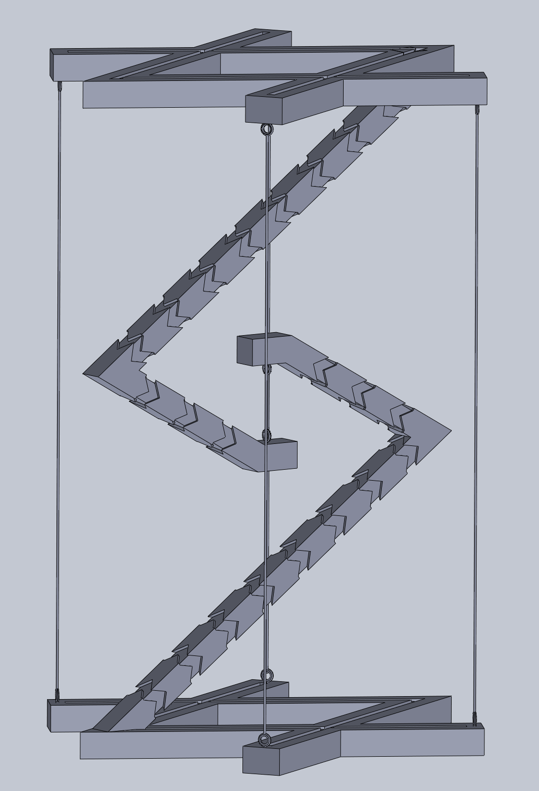
PDFThe Terrific Tensegrity Table functions as a table, yet miraculously appears to be floating. Standing at around 30 centimeters tall, the table is as functional as it is mind-boggling. This project wouldn’t have been possible without the infamous JasmineTHEBaller, however, who brought creativity and a keen eye to the table. Fishing line and hooks are necessary to complete the assembly.
Our client outlined his expectations and criteria with the following constraints:
- Design must take advantage of print orientation to create the strongest structure possible.
- Each piece should fit inside of a 15cm x 15cm square.
- When constructed, the final structure should fit in a 20cm x 20cm x 20ish cm cube.
- Parts must begin with a constraint box, center-rectangle centered on the origin)
- No single dimension can be smaller than 0.25cm
- All plates must have a thickness between 0.75cm and 1.00cm
- All beams should have a thickness of 1.00cm
- Engravings should be cut to a depth of 0.07cm
- Dimensions should be detailed but efficient.
- Sketches should be fully defined when complete.
- Parts must contain zero error messages.
- Structures must be assembled virtually before 3D Printing to ensure successful models.
Parts for printing:
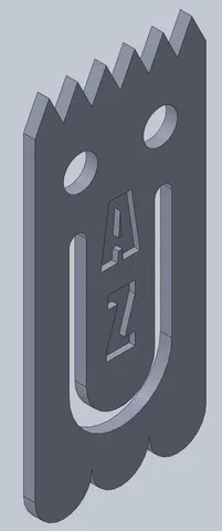
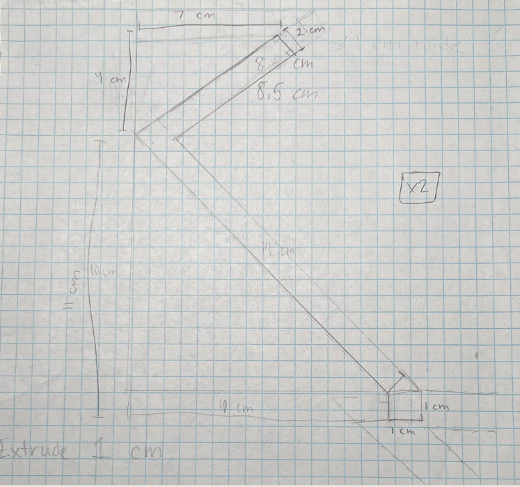
- Jaiden - Tensegrity Base REVISED (x1)
- Jaiden - Tensegrity Top REVISED (x1)
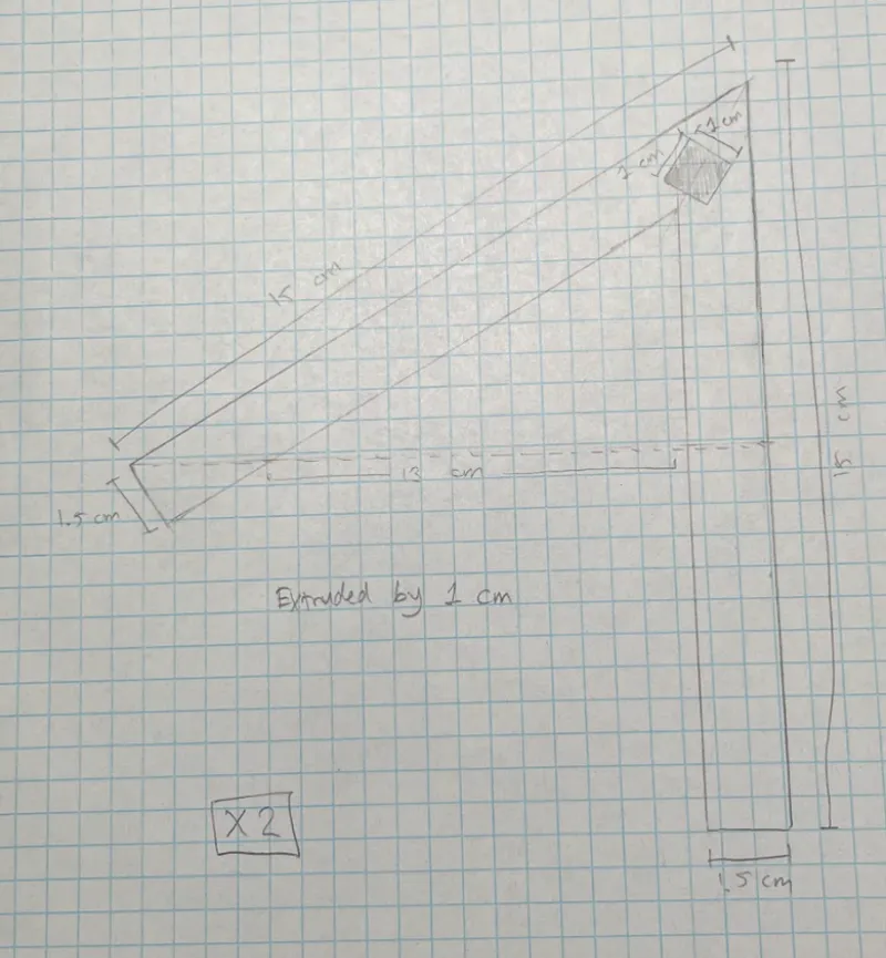
- Jaiden-Tensegrity Support REVISED (x2)
Tools for constructing assembly:
- Fishing Line
- Screw Hooks
- Drillbit
- Hammer
- Wire Cutters
- Pliers
- Hot Glue (optional)
Assembly Instructions:
1. Screw in hooks into holes on bases and supports, applying downward pressure and turning until each hook is secured into place (10 hooks in total)

- If you’re having trouble screwing the hooks in, widen holes by lightly hammering using a drill bit

- We recommend applying pressure and turning hooks using pliers for added leverage


- NOTE: The support beams are particularly fragile if hammering through. If the support cracks under tension, apply hot glue and clamp shut, securing a strong adherence.

Once the hot glue has dried, shave off any excess glue and resume screwing in the hook.

2. Piece together the structure, inserting the end of the support beams into the holes in the base/top.


- Wiggle the parts until a tight fit is met

- If needed for added strength, hot glue the seam shut


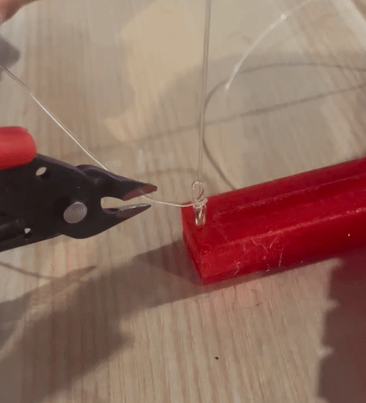
3. Cut at least 10 centimeters of fishing line to be stringed between the two support beams.
4. Intertwine the aforementioned line through the hooks on the support beams while your partner holds them upside-down over each other. Tie each end by fishing the line through the hooks and looping it back through the hole.

5. Measure out four additional fishing lines to be stringed between the bases for horizontal stability.
- Each line should be approximately 30-40 centimeters in length.

6. Intertwine the fishing lines through the pairs of hooks vertically lined up and tie a knot at each end.

7. Pull each string until they are all under equal tension, and rigid enough to support weight.
- A level can be used to properly balance the string tension.

8. Once all the strings have been tightened equally, secure the knots with pliers, and cut them about 2 centimeters from the knot.
Design Choices:
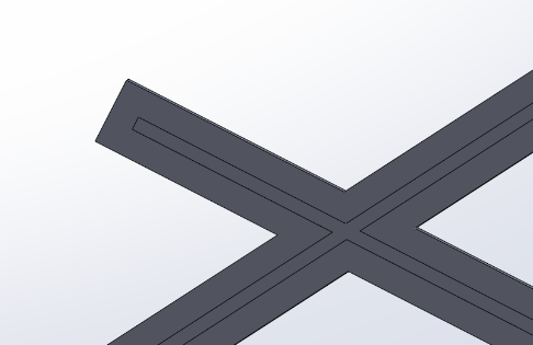
Comparing our final design in Solidworks to our initial sketches, it's clear to see that some alterations were made. Firstly, comparing our initial base / top sketch to the final iteration, the most prominent change is that rather than 2 spokes, there are 2 pairs facing in opposite directions. This change was made for increased stability with the vertical wires tensioning the structure upright.

Before After
Secondly, although the dimensions largely remained the same, we added a striped arrow pattern on the support beams, purely for aesthetic intrigue. You may also notice that a horizontal extrusion was added to the top of the support beam. This was to allow for easier hook connections between the vital load-bearing middle section of the structure.


Before After After-After
It’s important to note that in Solidworks we made the hole in the bases 0.4 cm larger than intended to account for the margin of error of the 3D printers we were using. Likely, if we kept the Solidworks hole 1 cm wide, the 1cm wide support beam would not have fit inside it.
From version 1.0 to 2.0 of our design, we made a few minor adjustments, some aesthetic, some functional. Most prominently, we altered our initials on the base plate to become far more aesthetically pleasing.


Before After
From the off-center lettering with the unnecessary periods and janky plus sign, we cleaned up the look, centering the letters and separating the initials. The initials are solely intended for the base of the structure, hence having two separate files for the base and top.
The other alteration we made to version 2.0 was to strengthen the support beams. At the angle of the beams, there was initially an indentation due to the arrow design. However, because this indentation at a critical point in the support beam weakened its strength, we filled it in, as pictured below.


This change was in an effort to minimize the support beams flexing, which in turn weakens the structure as a whole.
On the final files, we added hooks and wires to demonstrate their placement. It’s important to note however, that these were not fixed in place, rather centered using width mates, as they are not a part of the physical structure.


Additionally, whereas in our first iterations, we had to eyeball where to screw in our hooks, in version 2.0, the hooks are built into the design for ease of use, and to minimize the chances of cracking while hammering.

Before After
Model origin
The author marked this model as their own original creation.