25 Button MACRO Keypad

Description
PDF25 Button MACRO Keypad - controller with an Arduino Pro Micro. Uses keyboard switches, a reset button, and a LED.
Summary:
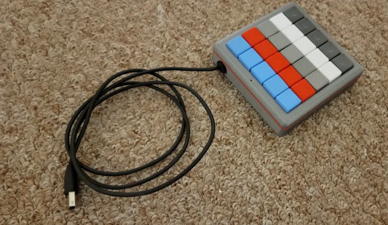
I designed this to be able to assign keyboard shortcuts for different software that I use on a regular basis. This MACRO keypad; in conjunction with JoyToKey will allow a great number of options for different software, batchfiles, shortcuts etc. Currently using it primarily for fusion 360.
Lists for Macro Keyboard V2 – as of 11/19/2022
Materials List:
- PLA filament
- TPU filament
- 25 Keyswitches (I used Akko switches)
- 25 diodes (1N4001 or similar)
- 1 LED (standard 5x9mm LED - any color)
- 220 ohm resistor (or whatever mates to your LED)
- 6x6x3.5 tactile button (1mm button height)
- Hookup wire (or cat5 solid core)
- HiLetGo Arudino Pro Micro
- X4 – M3 x 16mm screws (I used Phillips head)
- Soldering Iron
- Solder
- Micro USB to USB Cable (recommend at least 3’)
- Small Zip Ties
*** Some models May need to be oriented before slicing.
PLA Print List:
- X1 - 2mm Spacer (can choose a different color from base and top for flair)
- X1 – MacroPadBase
- X1 – MacroPadTop
- X1 – Reset Button (will be visible, can choose different color than base so it stands out)
- X1 – Reset Button2 (not visible) *Update 07-06-23 - shoutout to @iComputerFreak
- X1 – Reset Holder SlipOn (not visible)
- X25 – KeyCap1 (can choose different colors)
TPU Print List:
- x1 - Grommet
Optional TEST PLA Print:
- X1 – KeyCapPlate TEST1_TEST (to test keycap locking ability and spacing)
PLA Print Settings (Prusa Slicer):
- 0.20 mm Quality - Layer Height
- 2 Perimeters
- Generic PLA
- Supports: None
- Infill 15% - Gyriod
- First layer speed 15mm/s
TPU Print Settings (Prusa Slicer):
- 0.20 mm Quality - Layer Height
- Generic FLEX settings
The KeyCapPlate prints quick and will let you know if your switches will fit (14mmx14mm)
Build:
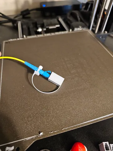
I have not done a full write up yet, but plan on doing that when I have the time. Photos should provide enough to go by for now.
When pressing the 3D printed Keycaps onto the switches, there is a notch on the switch which correlates to the “dot” on the 3D printed key cap; line those up and then press firmly. All key caps should pressure fit into place. You can remove them a few times without too much risk of them becoming loose.
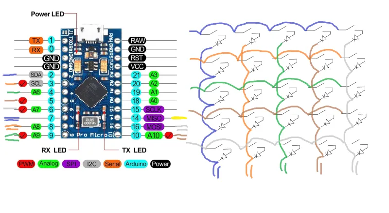
Wiring:
The key switches are wired into a 5x5 matrix.
Single color lines are for rows: Blue, Orange, Green, Brown, Grey
Double color lines are for columns: 2Blue, 2Orange, 2Green, 2Brown, 2Grey
The Yellow line is for the LED Output.
In the final wiring, I wired the columns backwards - so if you are following along the scripts below will work as I had to accommodate for this… Otherwise you may need to reverse the keys for the two test scripts. (In the final script, I flipped the colpins around so it reads more naturally in the script.)
Scripts:
Here are x2 Test scripts (.ino) and the final script that is currently being used.
* Serial Test Arduino Script:
Test Script to output only to serial monitor
#include <Keyboard.h>
#include <KeyboardLayout.h>
#include <Keyboard_da_DK.h>
#include <Keyboard_de_DE.h>
#include <Keyboard_es_ES.h>
#include <Keyboard_fr_FR.h>
#include <Keyboard_it_IT.h>
#include <Keyboard_sv_SE.h>

#include <Keypad.h>


const int ledPin = 14;// led Pin#
const byte rows = 5; //five rows
const byte cols = 5; //five columns
char keys[rows][cols] = {
  {'E','D','C','B','A'},
  {'J','I','H','G','F'},
  {'O','N','M','L','K'},
  {'T','S','R','Q','P'},
  {'Y','X','W','V','U'}
};
byte rowPins[rows] = {2, 3, 4, 5, 6}; //connect to the row pinouts of the keypad
byte colPins[cols] = {7, 8, 9, 10, 16}; //connect to the column pinouts of the keypad
Keypad keypad = Keypad( makeKeymap(keys), rowPins, colPins, rows, cols );


void setup() {
  // put your setup code here, to run once:
  Serial.begin(9600);
  pinMode(ledPin, OUTPUT);
  Keyboard.begin();
}

void loop() {
  // put your main code here, to run repeatedly:
  char key = keypad.getKey();

  if(key != NO_KEY){
    Serial.println(key);
    Keyboard.write(key);
    digitalWrite(ledPin, HIGH);
    delay(100);
    digitalWrite(ledPin, LOW);
  }
}
** Serial and Keyboard Strokes Test Arduino Script:
Test script to output to serial monitor and input keyboard strokes. Test in notepad.
#include <Keyboard.h>
#include <KeyboardLayout.h>
#include <Keyboard_da_DK.h>
#include <Keyboard_de_DE.h>
#include <Keyboard_es_ES.h>
#include <Keyboard_fr_FR.h>
#include <Keyboard_it_IT.h>
#include <Keyboard_sv_SE.h>
#include <Keypad.h>
//-Below is where we will define the keys
//-Variables are defined as following:
//-[keyA] [keyB] [keyC] [keyD] [keyE]
//-[keyF] [keyG] [keyH] [keyI] [keyJ]
//-[keyK] [keyL] [keyM] [keyN] [keyO]
//-[keyP] [keyQ] [keyR] [keyS] [keyT]
//-[keyU] [keyV] [keyW] [keyX] [keyY]

//------------Define 1st Row------------
//Ex: [keyA] [keyB] [keyC] [keyD] [keyE]
//--------------------------------------
char keyA = 'A';
char keyB = 'B';
char keyC = 'C';
char keyD = 'D';
char keyE = 'E';
//-Define 2nd Row-----------------------
//Ex: [keyF] [keyG] [keyH] [keyI] [keyJ]
//--------------------------------------
char keyF = 'F';
char keyG = 'G';
char keyH = 'H';
char keyI = 'I';
char keyJ = 'J';
//-Define 3rd Row-----------------------
//Ex: [keyK] [keyL] [keyM] [keyN] [keyO]
//--------------------------------------
char keyK = 'K';
char keyL = 'L';
char keyM = 'M';
char keyN = 'N';
char keyO = 'O';
//-Define 4th Row-----------------------
//Ex: [keyP] [keyQ] [keyR] [keyS] [keyT]
//--------------------------------------
char keyP = 'P';
char keyQ = 'Q';
char keyR = 'R';
char keyS = 'S';
char keyT = 'T';
//-Define 5th Row-----------------------
//Ex: [keyU] [keyV] [keyW] [keyX] [keyY]
//--------------------------------------
char keyU = 'U';
char keyV = 'V';
char keyW = 'W';
char keyX = 'X';
char keyY = 'Y';
//--------------------------------------
//-End of Defining Keys-----------------
//--------------------------------------

const int ledPin = 14;// led Pin#
const byte rows = 5; //five rows
const byte cols = 5; //five columns
char keys[rows][cols] = {
  {keyE,keyD,keyC,keyB,keyA},
  {keyJ,keyI,keyH,keyG,keyF},
  {keyO,keyN,keyM,keyL,keyK},
  {keyT,keyS,keyR,keyQ,keyP},
  {keyY,keyX,keyW,keyV,keyU}
};
byte rowPins[rows] = {2, 3, 4, 5, 6}; //connect to the row pinouts of the keypad
byte colPins[cols] = {7, 8, 9, 10, 16}; //connect to the column pinouts of the keypad
Keypad keypad = Keypad( makeKeymap(keys), rowPins, colPins, rows, cols );


void setup() {
  // put your setup code here, to run once:
  Serial.begin(9600);
  pinMode(ledPin, OUTPUT);
  Keyboard.begin();
  keypad.setDebounceTime(50);
}

void loop() {
  // put your main code here, to run repeatedly:
  char key = keypad.getKey();

  if(key != NO_KEY){
    Serial.println(key);
    Keyboard.write(key);
    digitalWrite(ledPin, HIGH);
    delay(100);
    digitalWrite(ledPin, LOW);
  }
}
*** MACRO KeyPad_Keypad-Joystick Script:
FINAL as built Working Script.
Hit win key > type “Set up USB game controllers” > click controller > Properties > Test. Will display a page and allow you to test the Joystick inputs.
#include <Joystick.h>
#include <Keypad.h>

#define NUMBUTTONS 25
#define NUMROWS 5
#define NUMCOLS 5
#define statLED 14


//-Define the buttons for the macropad
byte buttons[NUMROWS][NUMCOLS] = {
  {0,1,2,3,4},
  {5,6,7,8,9},
  {10,11,12,13,14},
  {15,16,17,18,19},
  {20,21,22,23,24},
};

byte rowPins[NUMROWS] = {2,3,4,5,6}; //-Connect to the row pinouts of the macropad
byte colPins[NUMCOLS] = {16,10,9,8,7}; //-Connect to the column pinouts of the macropad

//-Initialize an instance of class NewKeypad
Keypad macroPad = Keypad( makeKeymap(buttons),rowPins, colPins, NUMROWS, NUMCOLS);


Joystick_ Joystick(JOYSTICK_DEFAULT_REPORT_ID,JOYSTICK_TYPE_GAMEPAD,
  25, 0,                  // Button Count, Hat Switch Count
  false, false, false,     // no X and Y, no Z Axis
  false, false, false,   // No Rx, Ry, or Rz
  false, false,          // No rudder or throttle
  false, false, false);  // No accelerator, brake, or steering

void setup() {

  // put your setup code here, to run once:

  // Initialize Joystick Library
  Joystick.begin();
  pinMode(statLED, OUTPUT);

}

void loop() {
  // put your main code here, to run repeatedly:
  CheckAllButtons();
  delay(0);
}

void CheckAllButtons(void) {
      if (macroPad.getKeys())
    {
        for (int i=0; i<LIST_MAX; i++)
          {
            if (macroPad.key[i].stateChanged)
              {
                switch (macroPad.key[i].kstate) {
                        case PRESSED:
                        case HOLD:
                                  Joystick.setButton(macroPad.key[i].kchar, 1);
                                  digitalWrite(statLED, HIGH);
                                  break;
                        case RELEASED:
                        case IDLE:
                                  Joystick.setButton(macroPad.key[i].kchar, 0);
                                  digitalWrite(statLED, LOW);
                                  break;
                }
              }

          }
    }

}
***Note: Photos are of prototype model so uploaded models may differ a bit in appearance.
Tags
Model origin
The author marked this model as their own original creation.