TheUltiPad MK2 - Now with OLED Display and RGB Underglow!
Description
PDFUpdate 1/25/2025 - updated the firmware in the latest QMK build environment for the promicro, added .hex file and archive for the QMK build env in Linux.
TheUltiPad MK2 - Now with OLED Display and RGB Underglow!
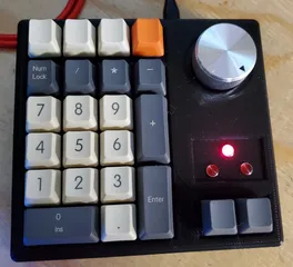
I have loved using my original UltiPad, used it every day since i first designed and prototyped it ... but it started to feel a little dated. An since the UltiPad is one of my more popular projects..and since i'm a glutton for punishment... i present TheUltiPad Mark Two! (something, something, still not good at names...)
It still has the 23 key number pad with media controls (four extra buttons at the top), Two function keys for multiple layers, and the rotary encoder... but now it has under glow (as much as you want!) and a neat little OLED screen to describe the layer, lock keys (num, cap and scr) and the under glow RGB settings.
The only hitch here, is I had some QMK Proton-c controllers sitting around waiting to do something, and i didn't realize that they are getting hard to come by...so i designed and built my prototype with the proton-c.
So...I went back to the drawing board and redesigned the lower half to support the USB-C versions of the pro-micro.
So now you have both, or either. You get to pick, that's what i'm saying.
I uploaded the raw QMK firmware folder (just download revere521.zip.txt and rename it to revere521.zip) and place it in the keyboards folder of your local QMK build env. - then you can customize/change the firmware and recompile to your liking.
There is a compiled hex (pro-micro) and bin (proton-c) if you just want to use what I compiled. Both firmware works and has been tested, and its essentially exactly the setup for the original UltiPad - with updates and additions for the OLED and Neopixel LEDs.
the only differences between the two are the proton-c version is setup for four (4) LEDs and the pro-micro version is setup for five (5).
Otherwise:
* The Keypad is the number pad as labeled
* The 4 top keys as PREV, PLAY, NEXT, STOP.
* The rotary encoder is Volume Up and Down, with the button as MUTE.
* The two bottom keys are setup as TT(1) and TT(2) (both a momentary and a toggle with double tap)
a. Layer 1 sets all the numbered keys (0-9) as LCAG(1), LCAG(2), etc. and i use autohotkey as an app launcher for LeftCtrl, Alt, Win + a number
b. Layer 2 sets all the numbered keys (0-9) as LCAG(A), LCAG(B), etc. and i use autohotkey as an app launcher for LeftCtrl, Alt, Win + a letter (a through j)
RGB Control:
* Fn + NumLock = changes the RGB Mode Forward (Alt + Numlock Reverse)
* Fn + Divide = changes the Hue forward (Alt + Divide Reverse)
* Fn + Multiply = changes the Saturation forward (Alt + Multiply Reverse)
* Fn + Minus = changes the Value forward (Alt + Minus Reverse)
Parts List:
* 23x Cherry MX switches of your choice
* There are recesses for Cherry MX Stabilizers but i am using it fine without stabilizers
* The [really nice mxuteuk 35mm machined aluminum knob](https://www.amazon.com/mxuteuk-Aluminum-Potentiometer-Electric-KNOB-06-34SR/dp/B07TY2YLX7) from Amazon
* Diodes: In4148 - (Amazon or Aliexpress, or wherever)
* EC11 Rotary Encoder - (Amazon or Aliexpress, or wherever)
* Proton-C - you can read about it and check stock at various suppliers [here](https://qmk.fm/proton-c/)
* Pro-Micro USB-C - you can get these from Amazon, or get the original from Sparkfun - [i used these](https://www.amazon.com/dp/B09DKBXMW6?psc=1&ref=ppx_yo2ov_dt_b_product_details)
* 1.3 inch OLED I2C Display [i used this one](https://www.amazon.com/HiLetgo-Serial-SSH1106-Display-Arduino/dp/B01MRR4LVE/ref=sr_1_3?crid=Z0QK6LBA9OGP&keywords=1.3+oled&qid=1666188552&qu=eyJxc2MiOiIyLjY0IiwicXNhIjoiMi40MyIsInFzcCI6IjIuNTIifQ%3D%3D&sprefix=1.3+ole%2Caps%2C163&sr=8-3)
* WS2812B LED buttons - [I used these](https://www.amazon.com/dp/B01DC0J3UM?psc=1&ref=ppx_yo2ov_dt_b_product_details)
* Any USB C cable for the Pro Micro or Proton-C
* 4x M3x14mm pan head machine screws (to assemble the case)
* 2x M3x6mm pan head machine screws (to attach the feet)
* 2x M2x4mm machine screws to attach the Proton-C only (pro-micro must be affixed with glue or double-sided tape)
* 4x M3x4x5 Brass threaded inserts (to insert into the TOP PLATE screw holes)
* Clear or White filament for the bottom of the case [i used this](https://www.amazon.com/dp/B07ZNG4L9P?psc=1&ref=ppx_yo2ov_dt_b_product_details)
* Various wire, soldier, etc. etc.
You can either print the individual 2 piece middle plate and bottom plate in clear, or print the one piece plate to about 4mm (at 0.2 layers that's at about layer 32) and switch to your filament from clear to a color like i did.
Print as many LED MOUNT discs as you want for the under glow buttons, or use a strip or something - your choice.
Some Printing Instructions
Print The following to have enough parts to assemble:
1x TOP PLASTE
1x DISPLAY COVER
2x FOOT
4,5 or ?x LED MOUNT (however many suit you - 4 for the default Proton-C firmware and 5 for the Pro-Micro default firmware though)
Then for the Bottom Half, pick either the Proton-C version or the Pro-Micro version; and your method.
Either print
1x MID SECTION
1x BASE PLATE
Or Print
1x ONE PIECE BOTTOM
Some Assembly Steps or Tips
If you have a pro-micro - flash your firmware prior to assembly! there is a port for the proton-c to hit the reset button after assembly, but the pro-micro clones often need the reset pin to be shorted to ground. The FN + ENTER on the keyboard puts either controller in bootloader mode for flashing again after assembly.
The OLED Display drops into the recess in the top plate, and the display cover simply snaps over it. you may need to sand the edges/corners of the cover slightly to get a good fit, its relatively tight but shouldn't be crazy. I then marked the GND, VCC, SCL and SDA pins on the back for easier hookup later. If you use pin headers with connectors, you will need to bend the pins to about 45 degrees on the back of the plate for wire clearance. Test fit everything.
Carefully heat set the screw inserts. You may want to run a drill bit through the holes to make sure to clean up any shrinking to elephant's foot. If you get the inserts out of place a little, you can widen the screw holes in the base a bit to compensate. Test fit everything.
Insert your stabilizers (if you use them) and your Key Switches. Solder your Diode matrix. The Columns and rows are the Same as the original UltiPad - but I'll add the diagrams, pin-outs and a fritzing if i can. Test fit everything.
Attach the feet with the small M3 screws through the bottom - so that you can avoid the screws with LED placement
Wire your button LEDs keeping track of the directions for Din and Dout. I used some ribbon cable to keep it simple. I glue the LED mount discs where i want them in the bottom of the case, then measure out my wire and solder the pads. Once i did, then i layed them back out in the bottom (facing down) and hot-glued them in place - that also works to cover the pads from shorts. Test fit everything.
For the LEDs, the proton-c can drive them (from pin A3) and the normal VCC 5v no problem - probably as many as you want. For the pro-micro, you must use the un-fused RAW 5v pin for the LEDs and the fused VCC pin for the OLED. 5 LEDs might be the limit there, idk.
The Pro-Micro needs to be attached in its recess in the lower half of the case with double-sided tape or hot glue. Just line the USB-C up with hole for the cable and stick it in place.
The Proton-c is attached with two M2 screws (upside down)
Solder or otherwise connect the pins for the rows and columns (tidy your wires), the LEDs to a pin for the Din driver, gnd and power, then your OLED to the gnd, vcc, sda and scl pins. again, i'll do my best to come back with pin-outs and diagrams. The important part here is - with all hand wired keyboards - keep your wires tidy, make sure they are long enough to be connected with the case open, but no so long as to make a spaghetti mess inside the case....
The Put it together!
Tags
Model origin
The author marked this model as their own original creation.


