CNC Z Axis Pointer
Description
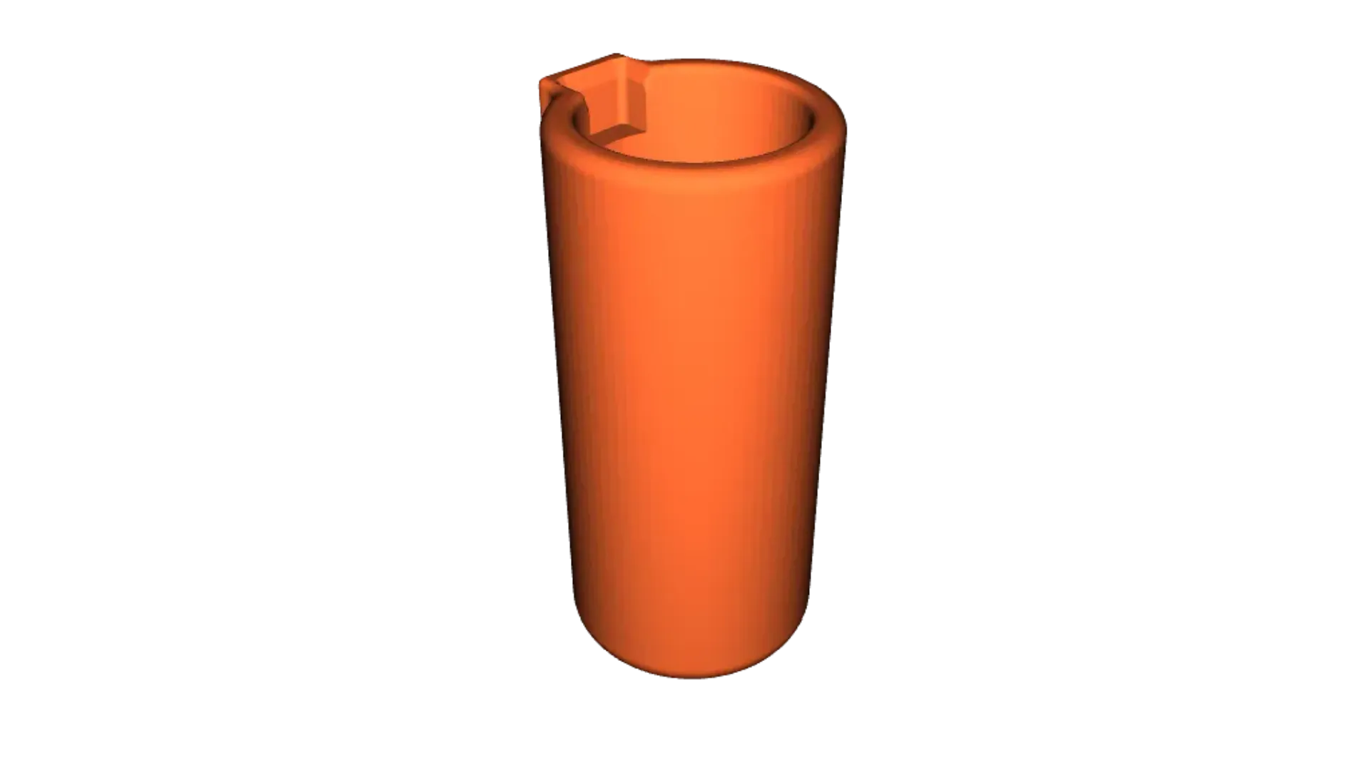
PDFFor positioning your spindle when CNC cutting. This pointer holder is for (reasonably) accurately finding the workpiece zero point before you start cutting. It doesn't find the Z zero, just the X and Y axis reference point.
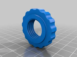
There are 3 versions, one for 3mm or 1/8" collets, one for 6mm or 1/4" and one replaces the ER11A compression nut completely
It's not difficult to find the X and Y home spot using a bit with a sharp point (V-bit) but you have to lower it till it is close to the surface to get reasonable accuracy. Can be a tedious procedure.
This holder accepts a cheap laser pointer and, after aligning it, you can drive all around your work area able to see where the spindle centre is.
You can check your material is big enough too.
There is a tricky part, aligning the laser pointer, they are not particularly well aligned when you buy them, for that you should buy a "boresight laser" but then you're talking much higher costs and a delay while some online shop ships it.
I don't suggest turning the spindle on unless you can set the rotation speed to a low value. Turn by hand to check the dots accuracy.
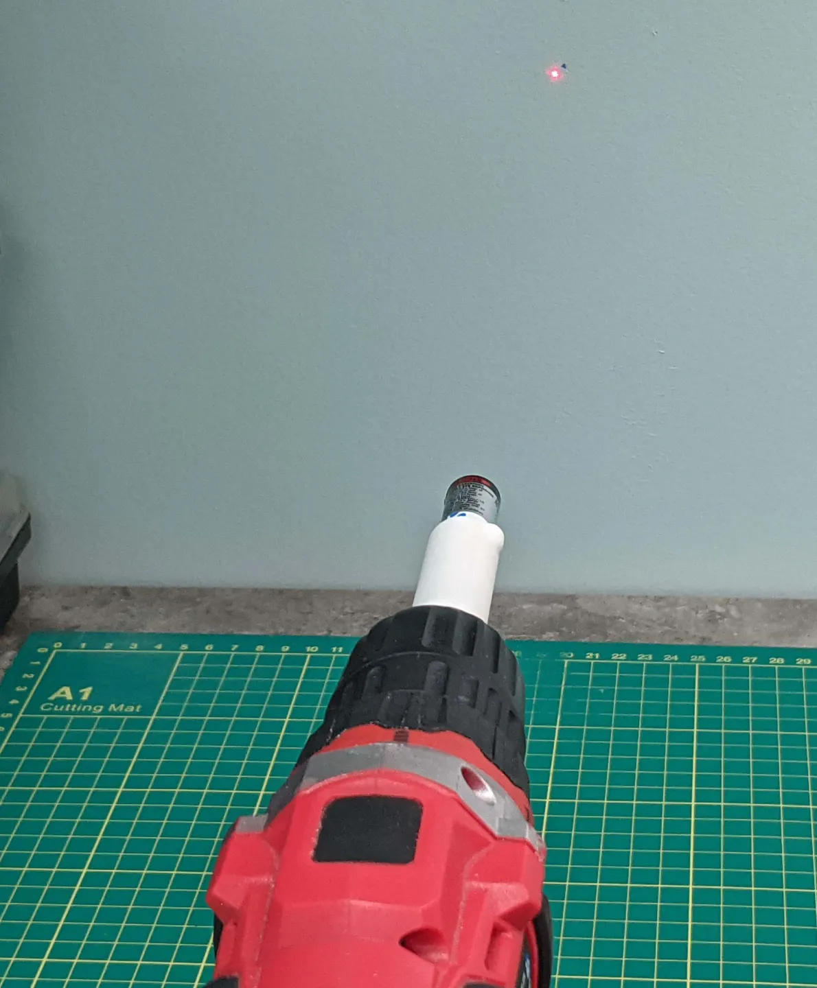
You can see that it's not perfect, if you run the spindle it will draw a circle around the zero spot and this circle can be quite small and easy to us for finding working zero.
Print with any material, open side up with no support. Maybe you like to use a brim for better adhesion for the tall print. I just use hairspray (on the print bed)
I use 1/8th" bits so I designed for it using a 3mm screw about 20mm long for the spindle collet chuck to hold onto, include a nut and washer to align properly and hold it securely. This replaces a 1/8th or 3mm tool.
I included a version that takes a 6mm pan head screw for 6mm or 1/4" collets, it's a few mm longer to account for the thicker screw head and the thicker back section.
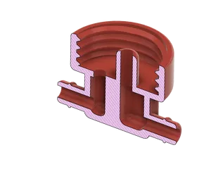
I also included a version where it replaces an ER11A compression nut and collet. Just screw your ER11A out and screw this one in.
It is quite long when the laser pointer has been inserted (70mm) and the screw adds about 20mm. To insert the device into the spindle you will need about 90mm of z-axis clearance. If you need a shorter version then I have one of those too, see the shorter Z axis pointer thing.
Print Settings
Printer Brand:
Creality
Printer:
Ender 3
Supports:
No
Resolution:
.2
Infill:
20%
Filament:
Amz PETG/PLA
White
Notes:
Printing the ER11 version may require super fine resolution to do a good job on the 0.75mm pitch threads. Print the same way, laser cup end up. No supports necessary but the contact area isn't that big, a brim may help bed adhesion (or use some hairspray). Takes about 95 minutes on my E3V2, standard resolution is obviously less.
Post-Printing =============
Cut the knob off the back of the laser pointer. It looks metallic but it is plastic.
Check the laser fits into the holder and that the button gets pressed as you push it in, there is a spot for the button. If its too tight then sand the inside, it's likely just blobs of material or uneven printing of the layers. If all else fails print again with a small amount of scaling adjustment in the x and y axes to make it bigger.
Too loose, add tape around the pointer or nail varnish in the holder to make up the difference.
Tricky part
Align the laser
Remove the front dome/cover, you will see than the laser is pressed into an aluminium tube. By tapping at the edge with a thin punch or nail you can adjust the direction it is pointing. I filed a nail flat and filed the sharp point off.
It takes a light tap to adjust, but by carefully holding the back of the pointer on a solid base and tapping the edge down, you can point the laser straight down its axis. I did 3 of these and after the first one you get the idea.

Cut the knob off the back

Tap pin to adjust alignment
Put it into a drill and point it at a wall to see how big the circle is when the drill turns. Adjust accordingly till the circle is as small as possible, preferable just a wide dot turning on its axis.
So now the laser is aligned but far too bright.
Use the wall to align the laser
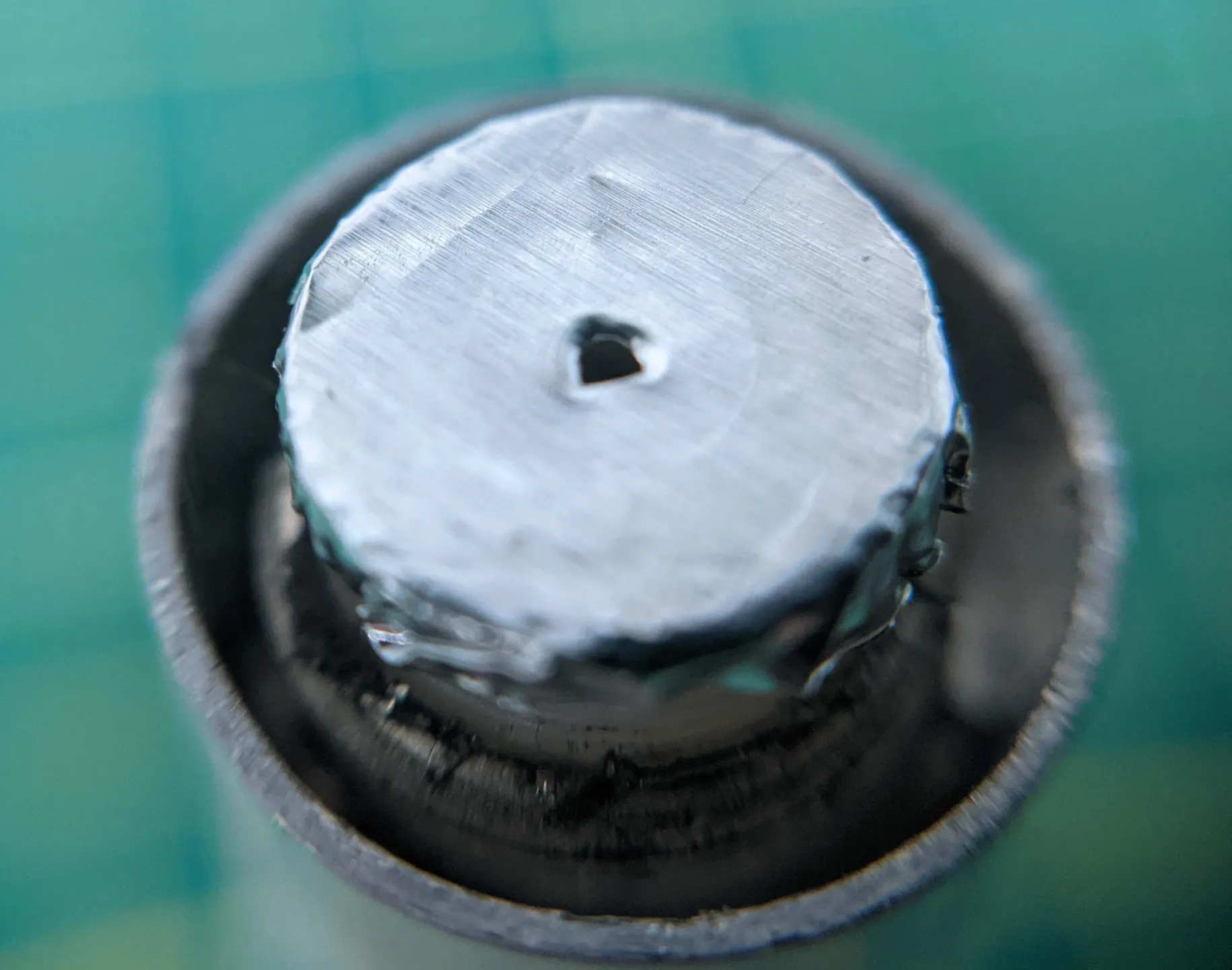
To make the spot smaller, add a pinhole to the lens holder or to the lens cover. I used a glue stick to stick some alumimium foil over the cover and pricked a 0.5mm (approximately) hole in the middle. Masking tape will also work.
You can also just stuff a short piece of wire insulation into the dome shaped lens cover.
If the laser is half decently focused at a distance you won't need to change the focus at all.
Use some adhesive tape to reduce the size of the laser dot
Reduce the diameter of the laser spot
Alternative designs
There are quite a few alternative designs including my shorter pointer
(In progress, will be added in a day or 2)
https://info.lagunatools.com/zero-in-on-your-origin
https://www.instructables.com/A-Laser-Guide-for-CNC-Alignment/
https://www.servomagazine.com/magazine/article/laser-alignment-system-for-your-cnc-router
and more if you search forcnc align with laser
Category: Machine Tools
Tags
Model origin
The author marked this model as their own original creation. Imported from Thingiverse.

