Carl's Desk

Description
PDFI made a CAD model, did some tests to see what would work and built this desk. It's called ‘Carl’s Desk', because the original was made for Carl.
This is a rebuild for the print tables contest, the 3D printed parts are now orange so they stand out, but you know… It looks great so I'm keeping the orange!
The connectors
Printed with 100% infill, the print orientation and settings I used are shown in the included print files.
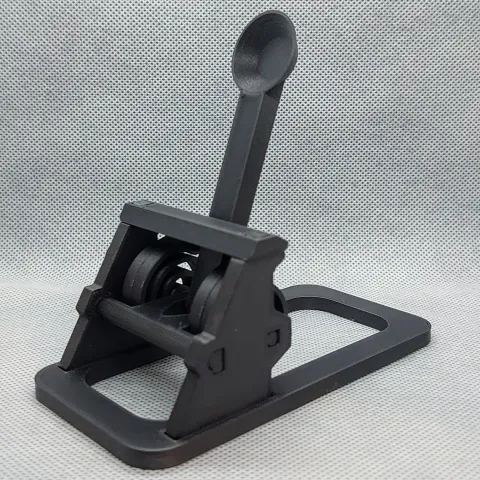
I originally designed the nut connector as a compression fitting that would expand to push against the tube as the nut was tightened. This design did work but I found a simple friction fit connector knocked in with a rubber mallet to be just as effective as the compression design.
As the nut was no longer needed to compress the fitting, I moved it closer to the joint, so I could use shorter screws. Doing this also appeared to make the joint more stable.
The desk frame
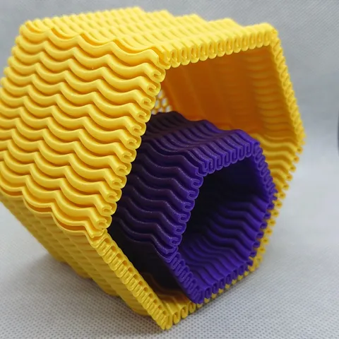
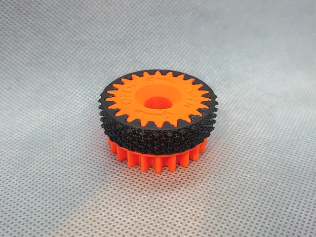
25mm Square Steel Tube with a 1.2mm wall, the connectors friction fit in the tube and hold an M8 Nut, the connectors are oversized by 0.4mm internally for the friction fit to work. Holding the nut in place is achieved by a small feature in the part; once the nut is fully seated it will stay in place.
Stability and Strength
The frame is surprisingly stable on its own, with the addition of the shelf, desk-top and vertical cable tidy board below the desk-top at the back, the thing is solid. It appears to be able to hold a fair bit of weight but I have not done any measured tests yet.
As this is a redesign, strength and rigidity have been improved over the original design. This was in regular use for just under two years, with no issues. (The last picture in the reel above is of the original desk, in which the 3D printed parts are Black PETG.)
Building the Desk
Bill of Materials
500g PETG Filament25mm Square Steel Tube 1.2mm Wall 2 x 150mm (Top a-frame link) 2 x 550mm (Bottom a-frame link) 2 x 1833mm (Front Leg) 2 x 1770mm (Back Leg) 5 x 1190mm (Cross Support)14 x M8 Hex Nut, 13mm between hex faces, 6.5mm tall, A2 Stainless14 x M8x45 Button Socket Cap Setscrews, A2 Stainless14 x M8 Washer, 8.4 mm ID, 16 mm OD A2 Stainless15 x 5.0x35 Countersunk Wood Screws.1 x Desk-top, 18mm OSB, cut to 650mm x 1200mm.1 x Shelf-top, 18mm OSB, cut to 306mm x 1200mm.1 x Cable tidy board, 18mm OSB, cut to 200mm x 1200mm.
Tools and Consumables
Angle Grinder - with some Cutting discs + 120grit or similar Flap Sanding Disc
Combi Drill - With Drill Bits For Steel 1.5-10mm set
Tape Measure
Speed Square
Centre Punch + cutting oil
Masking Tape
Pencil/Sharpie
Screwdriver with 5mm Hex bit and PH2 for the wood screws
Rubber Mallet
Paint for the steel Tube
The Build Guide
Before I go any further, work safely and measure as carefully as possible.
This is a fairly basic build guide, if you're unsure of anything, I suggest using the comments or asking a local maker/fabricator.
Step 1 - Print the parts and fit the nuts It's good to just have these ready to go. When the parts are printed, any that require a captive nut can be put together as a sub-assembly now. Insert the nut into the back of the connector, then put a screw through the other side and tighten until the nut is fully seated in the connector (Then remove the screw and repeat another 13 times). Note: if using power tools, stainless nuts and screws may bind, go slow. |
Step 2 - Prepare the steel Okay the cut list is above in the BOM, nothing fancy cut the steel square, to the above lengths, de-bur and clean up any cut ends. When the steel is cut to length, drill the holes, where they need to be, Hole positions are shown in “BackLeg_SA_Drawing.pdf" and “FrontLeg_SA_Drawing.pdf”. When done with cutting and cleanup paint the steel and let it dry. Note: This step is difficult and precision here is important, steel suppliers can usually cut your steel to length and sort out the hole positions for you. Or build the A-frames as best you can, they should both be the exact same size, lay them down on top of each other, and clamp them together, then just use a square from the back leg to mark side hole positions for shelves or desks or cross supports. |
Step 3 - All the Sub-Assemblies Drawings of all the sub-assemblies in this step are in the files section. You will need to put together the following Sub assemblies:
The 3D printed components, with or without nut inserts are all friction fit, just knock them into the ends of the steel with a rubber mallet, Line up the connector and tap it until the part is fully seated in the tube. Note: Print a couple of spare nut connectors, get an off-cut of the steel, and have a practice before making a start on the actual parts. |
Step 4 - Assemble the frame Start with the A-Frames, attach the legs to the top link using a rubber mallet, then attach the bottom link and tighten the screws. Note: Pay careful attention to the orientation of the legs here, removing the top connectors is annoying, even more so if you're hoping to re-use the parts… To complete link the A-frames with the cross supports, leave these screws a turn loose. Now tighten them, working up from the bottom alternating sides, while tightening the joint up check the frame is square at the joint you're tightening with a square. Here are some drawings showing the frame assembly steps, there's also a pdf drawing “PCdesk_FrameAssembly.pdf” showing the frame assembly as built. Note: All the drawings are A4 so can be easily printed out and should be okay when viewed on a smartphone. 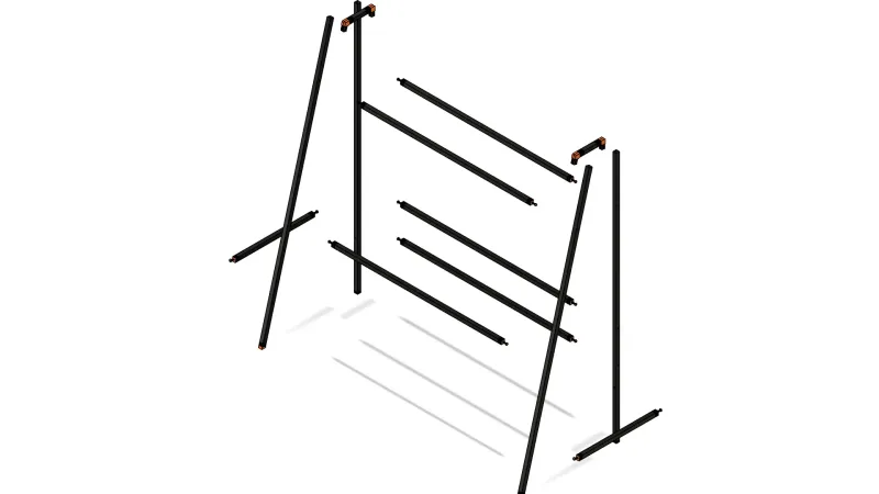 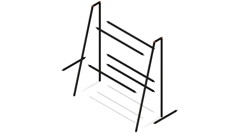 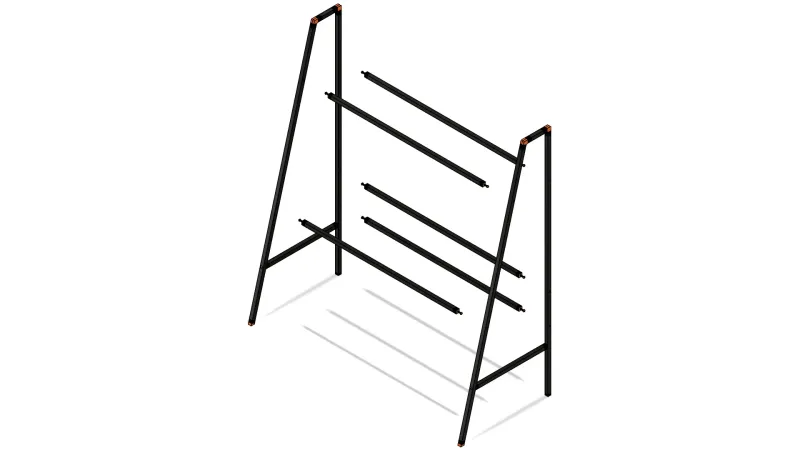 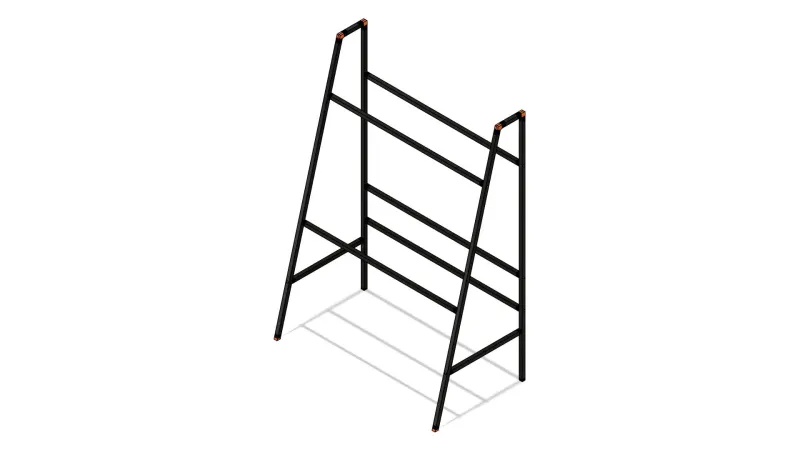 |
Step 5 - Desktop/Shelf/CableTidy The cable tidy board should fit perfectly between the two cross supports at the back below the desk. This is secured in place by three woodscrews through the top cross support and three in the bottom from underneath through the bottom cross support. [Drill 5mm holes straight through and countersink so the screws are flush.] The top shelf is secured by six woodscrews from underneath the cross supports, three on each support. The Desk top is secured by three woodscrews from underneath the front cross support, and a single self tapping screw in the centre at the back. You would think i might have made a more elegant solution for this, someday maybe, not today sorry, you're stuck with through frame screws for now… |
Step 6 - Enjoy, take a picture, post a make. I should have taken more pictures the first time I built this, pictures of the mistakes, the wins, the moments of “I knew this would fail, so I built it to try prove myself wrong… apparently I was wrong… :D". |
These instructions may change, there are probably some minor mistakes, but they'll get you there, unsure of anything, please ask in the comments. - AM
Tags
Model origin
The author marked this model as their own original creation.