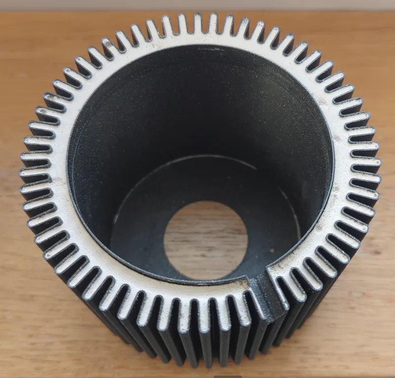
Lamp cannelé design - Vase mode - Bed side lamp

Description
PDFReminiscent of the renowned pastry from Bordeaux (France) le Canelé Bordelais, the main design element of this lamp is known to french mechanics engineers as cannelure.
I designed this lamp with the goal to utilize the spiral-vase 3D printing mode to create a beautiful object, with a minimalist, retro, industrial style.
Replicating this lamp for yourself requires more than a 3D printer ! Please read the instructions below carefully, in order to plan the material and the construction steps.
⚠ This lamp is only compatible with LED light bulbs ! Do not use any other type of light bulb or you risk to melt your lamp ! ⚠
Bill of material (for 1 lamp)
- 120g/40m of filament for the BASE, I used Prusament PLA Galaxy Black
- 390g/130m of filament for the SHADE, I used Prusament PLA Marble Grey
- 100g of hobby plaster: example from Amazon.de
- 350g of water
- 15g/14ml of long work-time epoxy glue (2 part epoxy syringe, 90min work-time): I used this one that I found in my local hardware store
- 1x E27 lamp socket: I found mine on Amazon.de
- 1x power cored with switch: I found mine on Amazon.de
Building the BASE
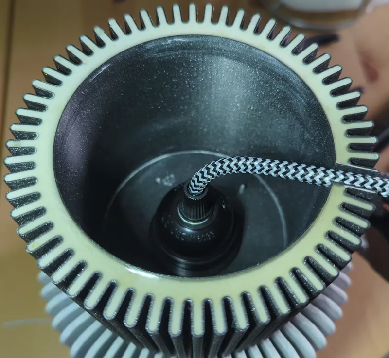
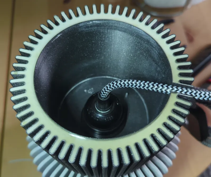
The base is printed in spiral vase mode in a way that creates a “double wall”. The volume created can then be filled up with plaster to give the base more weight. The extra weight is important to ensure the complete assembled lamp is stable, stays in place and doesn't tip over easily, like we would expect any lamp to be.
3D printing parameters for the BASE
Follow these instruction carefully if you want a successful print with a 0.4mm nozzle using PLA. I believe the model would be much easier to print with a wider nozzle (0.8~1.0mm) but 0.4mm is all I have to try. All the details are given for PrusaSlicer. The .3mf project files are available with all the settings already dialed in.
- Print settings: Layer height: 0.20mm, SPEED preset
- Activate Spiral vase mode: Print Settings > Layers and perimeters > Vertical shells > Spiral Vase. A dialog will notify you other settings will be adjusted automatically, accept.
- Set number of Bottom layers to 6: Print Settings > Layers and perimeters > Horizontal shells Solid Layers. Set to 6.
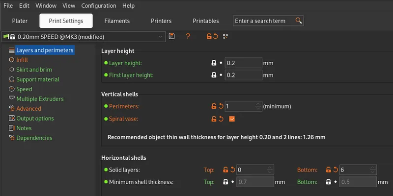
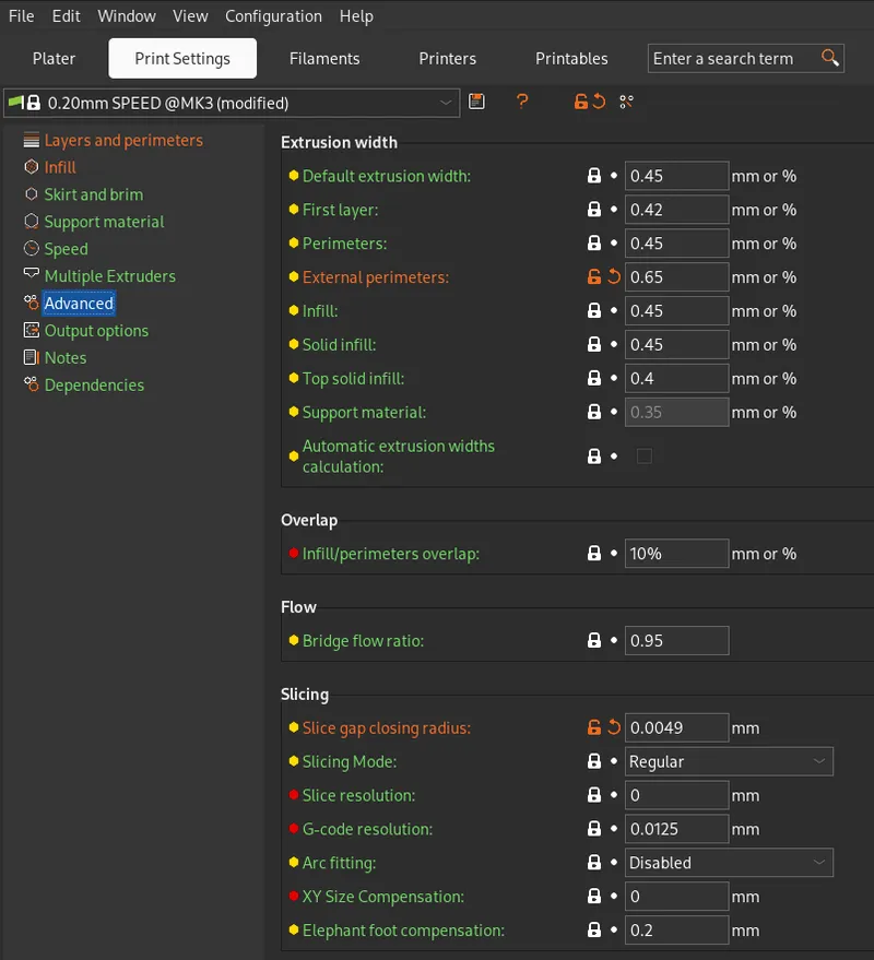
- Increase extrusion width of external perimeters: Print Settings > Advanced > Extrusion width > External perimeters, set to 0.65mm. This will print well event with a 0.4mm nozzle, it will help greatly increase the rigidity of the final part and also help with quality of the overhangs
- Reduce Slicing gap closing radius: Print Settings > Advanced > Slicing > Slice gap closing radius, set to 0.0049mm. The double-wall is achieved in the design by creating a “C-shaped” perimeter were the opening of the “C” is 0.01mm wide. The 2 paths must fuse together while printing. But such small detail would be “optimized” (removed, ignored) by the slicer. Adjusting down the Slicing gap closing radius below 0.01/2 ensure this crucial detail is not lost.
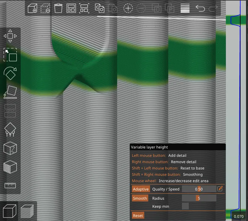
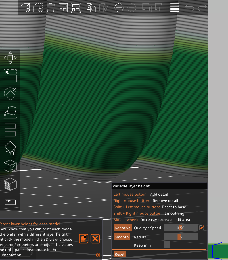
- Variable layer height: Enter the variable layer height mode with the icon on the top tool bar. The variable layer height needs to be adjusted manually:
- leave minimum 3 layer at the bottom the the default 0.20mm layer height
- decrease layer height to the minimum value of 0.07mm for the curve at the bottom of the part, for better printing of the overhangs
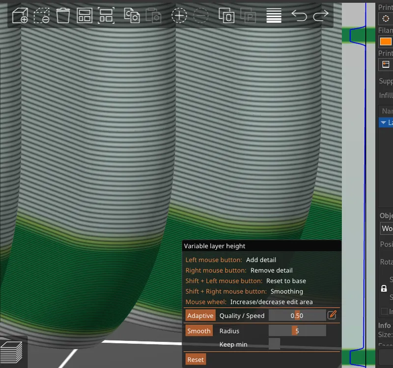
- decrease layer height to the minimum value of 0.07mm at the arch junction where the power cord will go.
You are ready to slice the model ! The slicing will take a while, it take a good minute on my desktop computer.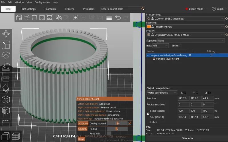
After slicing, make the following verification. The junction point of the double-wall is generated properly, activate the Travel in the preview verify. If the Slicing gap closing radius is set properly, the wall will be generated properly, if it's not, some tool-path will be generated between the inner and outer walls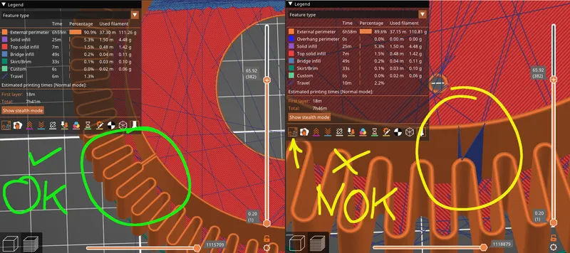
3D printing the BASE
Use a smooth print surface, make sure you have good layer adhesion or use some glue. Open up your printer's enclosure if you use one, during the printing of the bottom curve of the model, better cooling will improve the quality of the overhangs. Once you printer has reached the straight area, you can close you enclosure and even speed-up the print.
Give the BASE some weight
Prepare plaster with a 1:1 volume ratio of plaster powered and water. Mix 300ml of plaster (~100g) with 300ml of water. (this will leave you with extra). Once well mixed, pour it carefully in between the inner and outer walls of the BASE. If you have to spill some plaster mix, try to spill it in the inside of the lamp, as it may be difficult to wash in between the layer lines, although it washes easily with water. Fill with plaster as high as you can without spilling.
Place the base on a paper towel and let dry for at least 24 hours. The model will leak a small about of water, but should not leak plaster mix.
To seal-off the plaster, I decided to use epoxy glue. You can think of other materials, in my case 2-part epoxy syringe are easy to procure and get the job done. 15ml is enough to do 2 lamps. Working with epoxy is messy: prepare some paper towels and were rubber gloves the whole time. I also found a toothpick and some rigid cardboard to help me spread the gooey epoxy evenly.
Building the SHADE
The shade is a simple 3D printed part and does not require further post-processing
3D printing parameters for the SHADE
Much like the BASE, the SHADE is a spiral vase print, that requires some special slicing parameters to print well with a 0.4mm nozzle. Project .3mf files with all the parameters dialed-in are available for download.
- Print settings: Layer height: 0.20mm, SPEED preset
- Activate Spiral vase mode: Print Settings > Layers and perimeters > Vertical shells > Spiral Vase. A dialog will notify you other settings will be adjusted automatically, accept.
- Set number of Bottom layers to 6: Print Settings > Layers and perimeters > Horizontal shells Solid Layers. Set to 6.
- Increase extrusion width of external perimeters: Print Settings > Advanced > Extrusion width > External perimeters, set to 0.65mm. This will print well event with a 0.4mm nozzle, it will help greatly increase the rigidity of the final part and also help with quality of the overhangs
- Variable layer height: Enter the variable layer height mode with the icon on the top tool bar. The variable layer height needs to be adjusted manually:
- leave minimum 3 layer at the bottom the the default 0.20mm layer height
- decrease layer height to the minimum value of 0.07mm for the curve at the bottom of the part, for better printing of the overhangs
3D printing the SHADE
Use a smooth print surface, make sure you have good layer adhesion or use some glue. Open up your printer's enclosure if you use one, during the printing of the bottom curve of the model, better cooling will improve the quality of the overhangs. Once you printer has reached the straight area, you can close you enclosure and even speed-up the print.
Final assembly
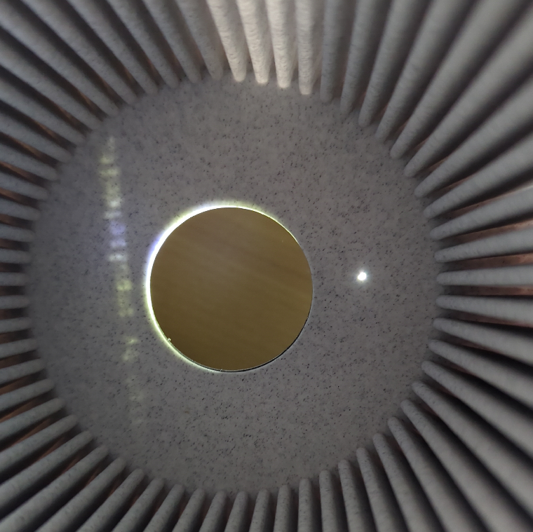
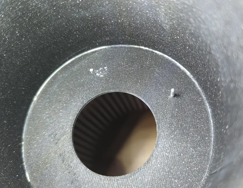
- Bring the BASE and SHADE together, flat bottoms against each other
- lineup the alignment holes (this ensure the cannelure line-up all the way)
- Cut a small piece ~2cm long of 1.75mm filament from you spool and use cutting pliers to make one end sharp
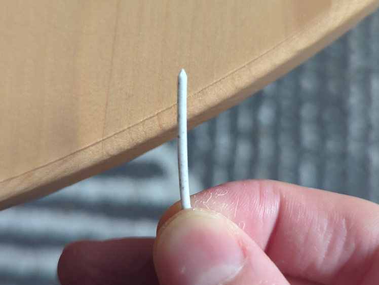
- Use flat pliers to push the filament through the alignment hols, through the shade and the base
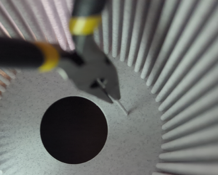
- It should hold like that, but you can also use the flat pliers to crush the tip of the pin, to make sure it stays in place on both ends
- Assemble your socket and cord together
- Assemble the socket inside the lamp, accession though the bottom of the base
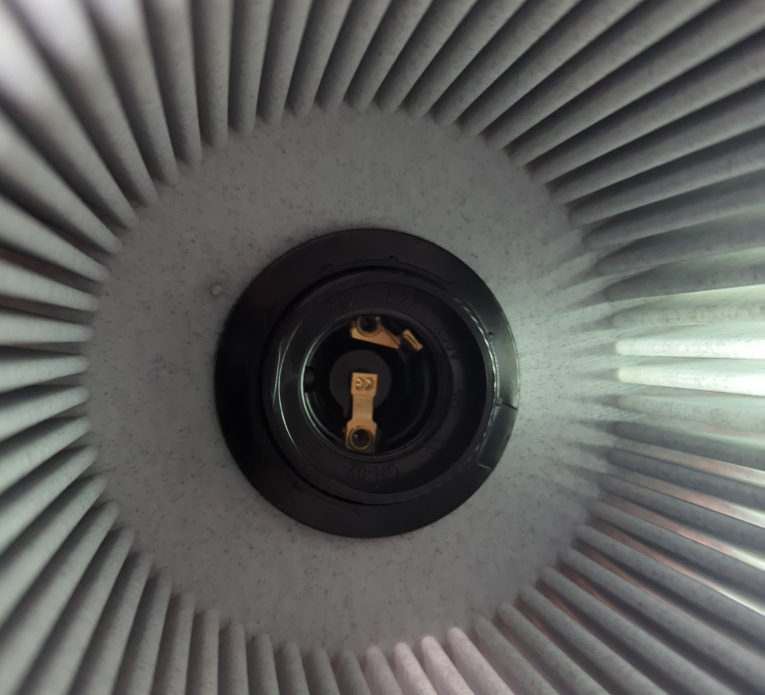
- Screw-in a light bulb and test your lamp !
CAD Project
You can find the CAD source project on onshape: Lamp cannelé design | impulse1delta | onshape.com
Tags
Model origin
The author marked this model as their own original creation.