Motor buffer for MMU in Samla Box


Description
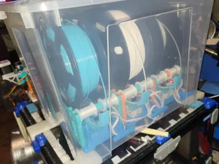
Video
in action
Working with PRUSA MMU3 and MK4S


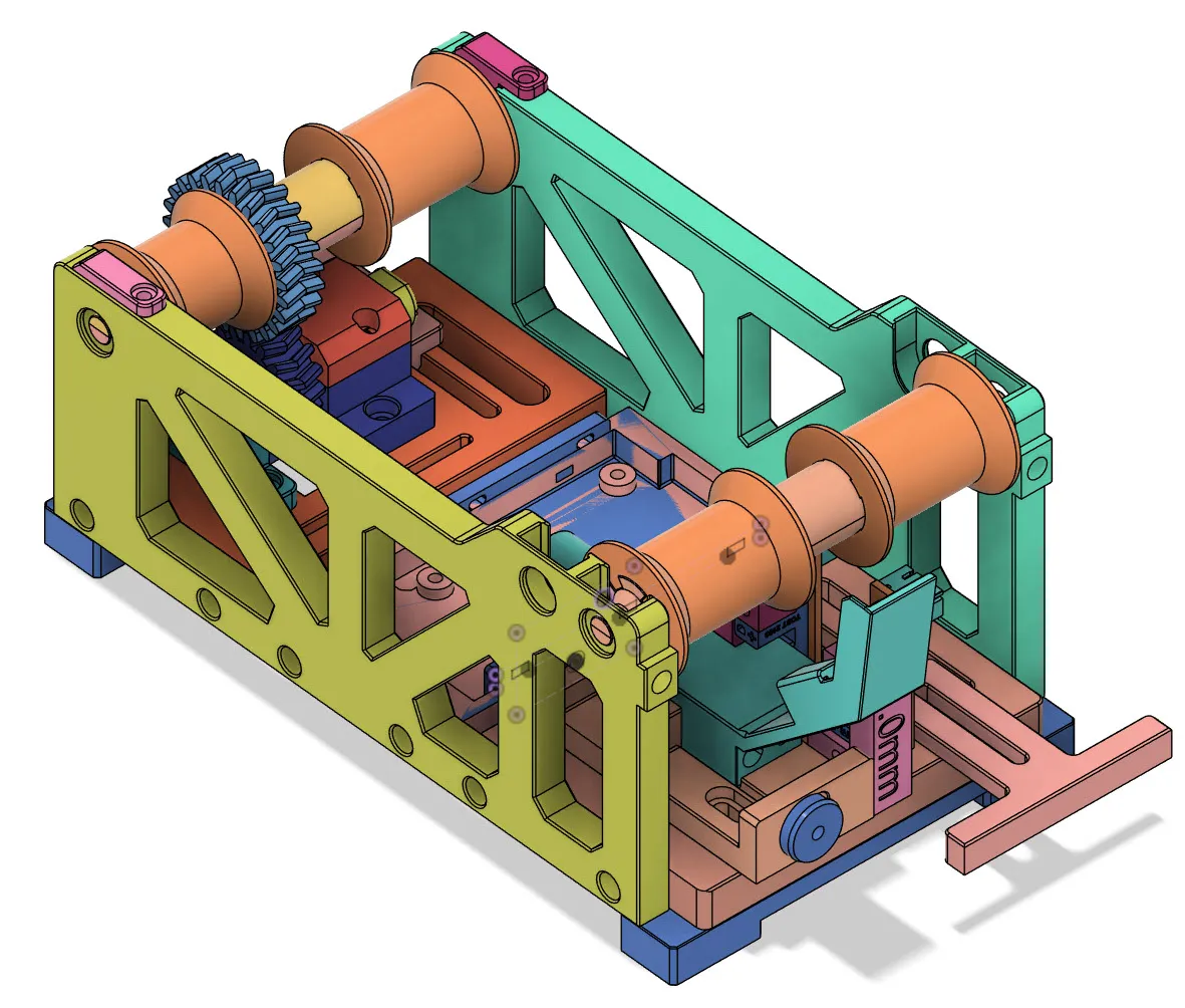
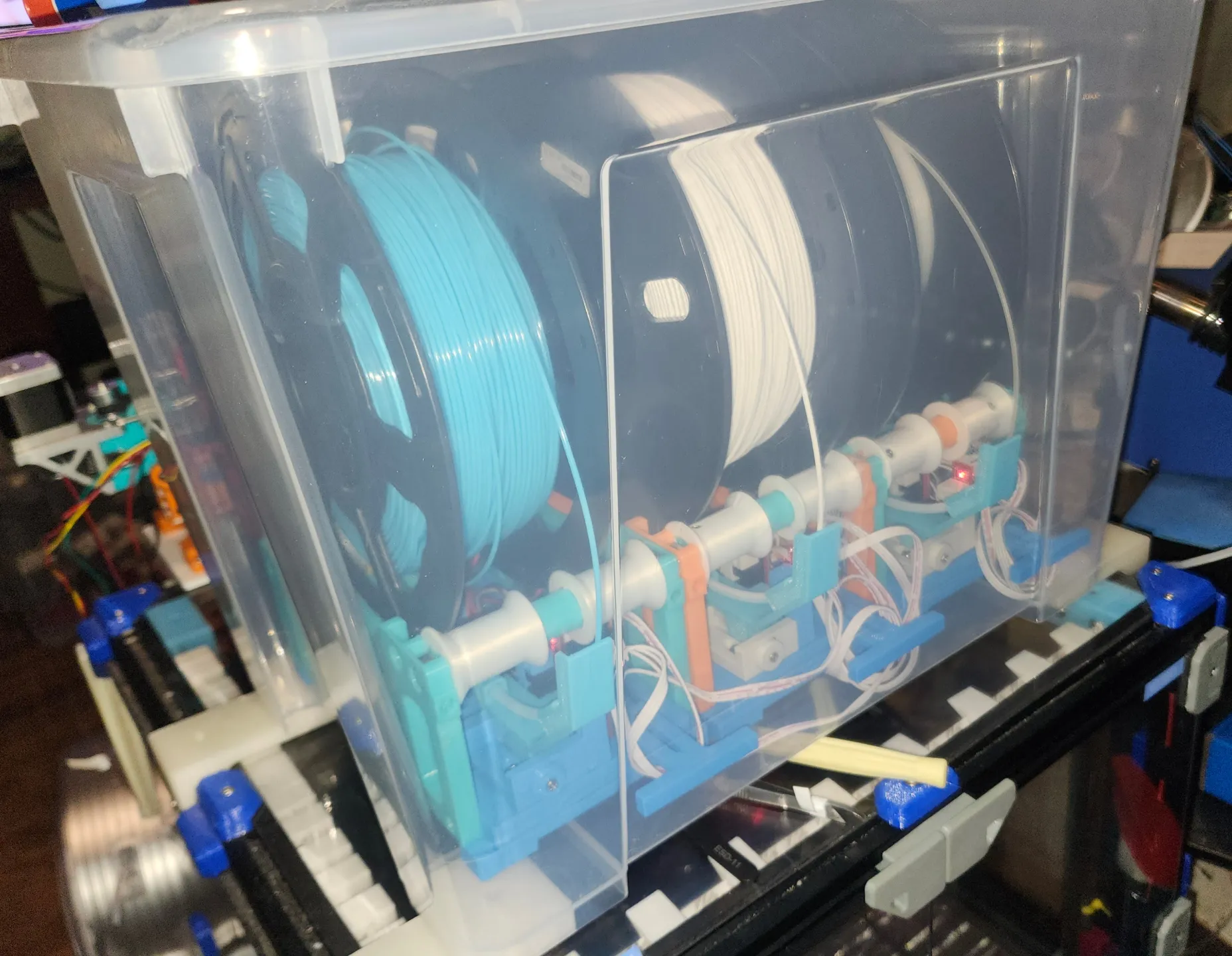
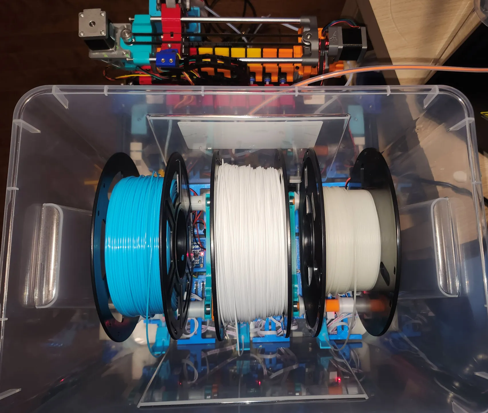
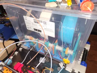
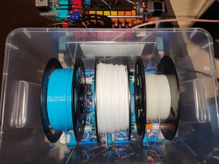
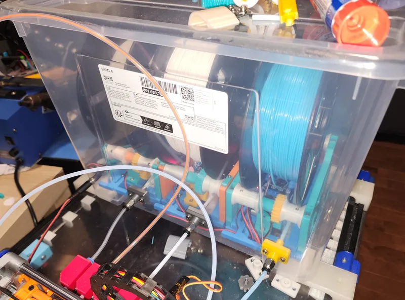
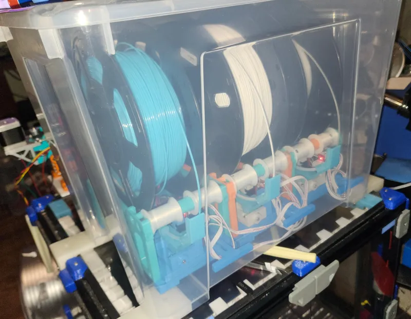
put 3 units in samla box (22L)
motor buffer connected with ERCF v2
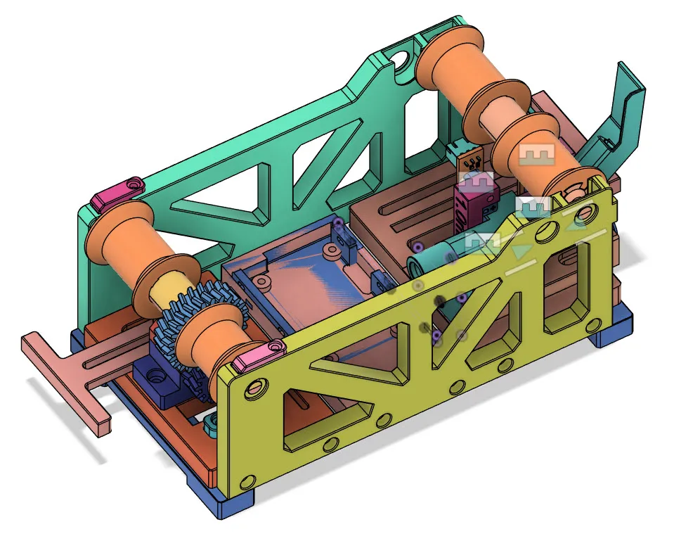
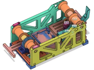
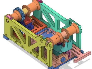
What is this
This is a buffer system for different multi material systems. It uses motor, to automatically do both filament rewind and release the filament from spool.
It works for different Voron printers (Trident, V2.4 etc) with ERCF and Prusa MK3(S) and MK4(S) with MMU3.
Also it's designed to put 3 units in IKEA Samla Box (22L) to keep filament from room air, dry, and with potential silica gel box within, we can make filament even drier.
No electronics signal is exchanged between this motor buffer system and the multi material system (PRUSA MMU3 or ERCF etc), therefore, it should be compatible with most of those.
Main Functions:
- This is a motor buffer system to works with Enraged Rabbit Carrot Feeder (ERCF V2, V1), PRUSA MMU3 (or MMU2), TradRack, 3D Chameleon, SMUFF etc, any multi material system without a box or container for spool s.
- This system by itself is NOT a multi material system. It's a motorized buffer system to work with different mmu.
- Help to easily store and manage filaments using IKEA Samla box (22L) and use them (printing) at the same time, keeping filament dry, easily stack two or three boxes, easily manage 3, 6 or 9 spools of filament.
Benefits of this motor buffer System:
- No buffer wheels, saving time and effort when changing filament. Routing filament multiple rounds on the buffer wheel is not very easy and require some time to do. Loading and changing different filament spools is much easier and straight forward.
- No buffer wheel, much easier for MMUs to pull filament from the buffer system, since buffer wheel creates certain resistance/friction. With this motor buffer system, motor help to rotate the filament spool to release and loose the filament, this makes mmu very easy to pull filament out of the spool.
- Rewind released filament (from MMU or printer) back into the spool
- Very low cost for hardware/electrical parts. a few bearing and motor, Arduino, driver board, magnet, screws. Around 7$ one unit and 3 units in a Samla Box (22L). (YMMV)
- Wide compatibility, because no electronic signal is exchanged between mmu and this buffer system, no connection between them, it works with most mmu in the open source area or market. This buffer system can sense the filament movement and automatically release or rewind filament accordingly, and stop doing so when it should. It works with Enraged Rabbit Carrot Feeder (ERCF) , PRUSA MMU3, Trad Rack SMUFF and so on.
- Samla box (22L) is very cheap and easy to buy.
Compatible List:
- Voron printers with ERCF , TradRack, Chameleon, SMUFF etc.
- PRUSA MK3S, MK4S with MMU2, MMU3, potentially Core ONE with MMU3 ( without crazy mod/addon to box the spools )
- Bascially all MMU systems without spool container, no signal wiring is needed between this and printer and mmu. ( However power 24V or 12V is still needed. )
Not Compatible list
- Not working with Bambu AMS, Creality CFS , or not needed. They have their own filament spool rotating management system and box/container.
- Not working with any open source or close source multi material system with its own filament container/spool rotation system.
- Single filament printer system, there is not much value using this motor buffer without a multi material system, you still can use it, it should help to rewind the filament.
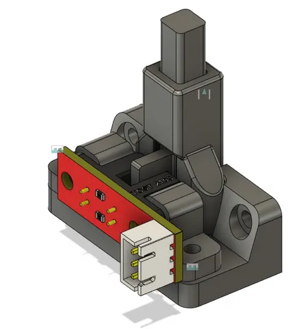
How it works
- This motor buffer system has a sensor can sense filament movement in two directions.
- When printer /mmu unload, filament tries to get in buffer system, it triggers the filament movement sensor, motor is turned on and rotate the roller, spool rotates and rewind the filament. After filament rewind enough, the sensor is not triggered and motor is turned off.
- When filament is being pulled out of the buffer system (slowly printing, or higher speed initial loading), the filament movement sensor is triggered in another position, motor is turned on and rotate the spool to release filament, it makes the MMU system very easy to pull the filament, MMU small gear no need to rotate the heavy spool.
- The motor buffer system also uses a Arduino module to help to better manage the motor turn on/off time, and to add a few different necessary safety features….ie even if the filament is stuck/sensor stuck, the motor won't get crazy and keep releasing the whole spool.
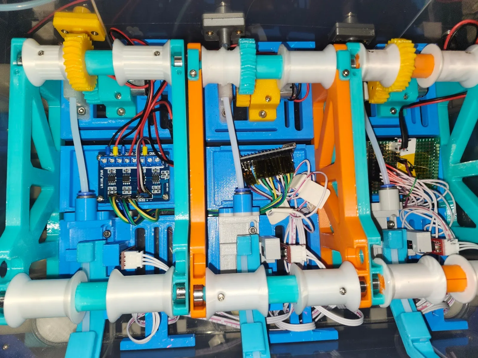
BOM, parts needed
For one unit (runs one filament spool):
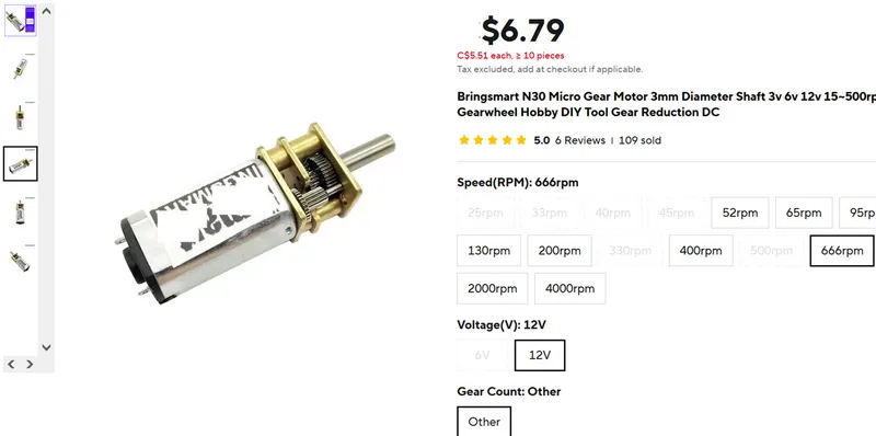
- N30 motor with gear, 12V, 666RPM, X 1 PCS
- Bearing 686ZZ, size 6X13X5( ID 6mm, OD 13mm, thick 5mm), X 4Pcs
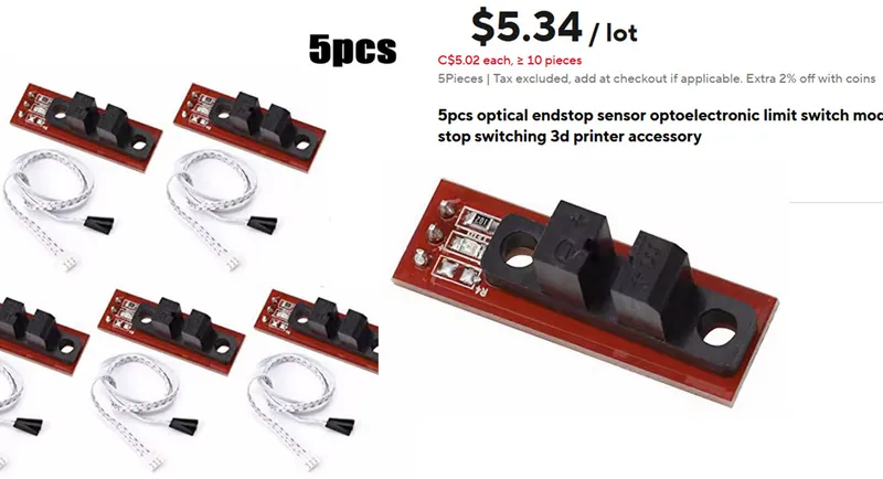
- Optical endstop sensor (Infrared sensor), X 2pcs. About 90 cents each
- Arduino Nano ( small arduino board). X 1Pcs (One arduino can drive 3units in a Samla box). I think other MCU module works too.
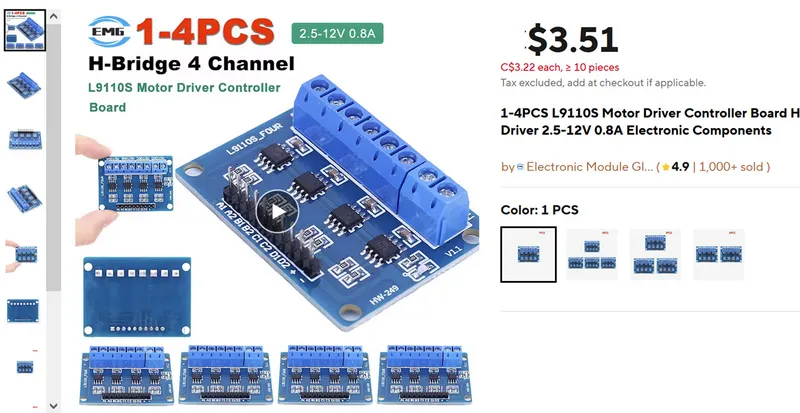
- L9110S Motor Driver Controller Board. X 1Pcs ( one board can drive 3 motors or 3 units in one Samla box)
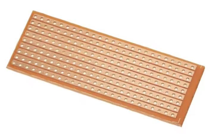
- Small PCB with holes prototype board. X1 PCS ( good for 3 units). There are different types of holes pcb in the market, all should work.
- DC Buck converter step down module 24V to 12V, preferred adjustable, so we can get about 11V. One for 3 units. Most 3D printer uses 24V (Voron, Prusa MK3,4 etc). Our motor need 12V. One for 3 units. Most module works, our application doesn't need high current. About 1-2Amp is enough. Alternatively, can also use a 12V standard power supply from AC with DC 5.1mm jack
- Smaller DC Buck converter step down module 12V to 5V preferred adjustable so we can get 5V. one for 3 units. for optical sensors only. Any small module should work. One for 3 units.
- Optional , common diode like 1N4007 or 1n5819 etc, any type should work, SMD or TH, just to prevent back power. X 2 PCS
- 2.54mm pins header. To put on the hole PCB to connect optical sensor wires/connectors, solder free, and connect arduino Nano pins.
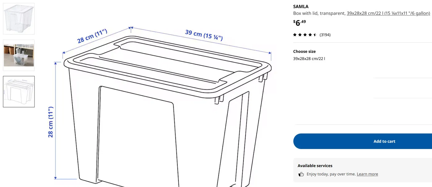
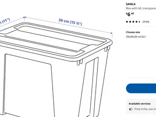
- IKEA Samla Box 22L or 6 Gallon ( 801.029.76), size 39X28X28cm. and top cover. One box can hold 3 buffer units or 3 spools.
- DC Jack or any DC connector you choose. One for 3 units.

- round magnet 6mmX3mm X 4PCS
- M3 socket head machine screws 8mm X 14pcs and heat inserts.
- M2.6 self tapping screws 8mm.
- M3 self tapping screw 8mm X 4.
- PTFE tube ID 2mm (OD 4mm as always, in 3D printing world)
- PTFE tube ID 3mm (or ID 2.5mm, but ID 3mm works better. ID 2.5mm has higher chance of stuck if filament is deformed )
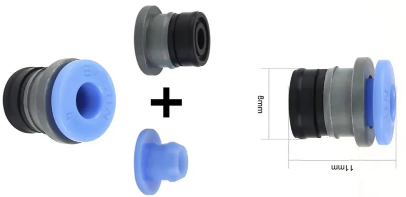
- ECAS04 ptfe tube connector(same used in ERCF and a lot of mods)
- nail dia 2mm (insert into PTFE to make it strong and straight) X 1PCS
For 3 units (runs 3 filament spools) with one Samla Box:
- everything above X 3, but we only need one Arduino, one motor driver board, one DC jack connector set, one DC buck step down 12V and 5V, one holes PCB , one DC connector set, and one Samla Box. 3 buffer units can share a lot of of common components.
Filament
To print this motor buffer system we need to print PLA or PETG, and TPU.
Most parts can be printed using PLA and PETG. Darker color for optical sensor light blocking part.
TPU is only for soft roller, so it can better drive spool to rotate.
Skills and knowledge Required
- very basic soldering skill is needed. need to make some 12V, 5V, GND power rail on the hole PCB, to connect some wires, pins and the DC buck converter.
- Need to understand what is 24V 12V and 5V and Gnd and make correct connections.
- Need to know how to deal with a Arduino and flash firmware.
Print Setting
- PLA or PETG.
- print N copies for file name has XN
- TPU for <main> TPU_roller_A and TPU_roller_B_X3: infill 10%, perimeter/wall:1 to make it soft. if it's too hard, it cannot effectively untrigger the input sensor. YMMV. different brand TPU need different settings.
- Darker color for <push_pull_sensor> dark_push_pull_sensor_simple.stl part.
- infill 30% or up
- wall/perimeters 3 or 4
- External Perimeter First enable for outter and inner for better dimensional accuracy
- for example in super slicer , Print Settings, Perimeters and Shell, lower part of the page.
- in Prusa Slicer, Print Settings, Layers and perimeters, lower part of the page, Check box for External Perimeter first.
- No support for all parts, no brim needed
- all parts are in correct orientation.
Print a small test part test_bearing_size.stl to test dimensional accuracy and print settings. Try to hand press in a bearing 686ZZ, (size 6X13X5). The goal is to hand push the bearing in, not too hard to push it in, but also not too loose to easily get out.
Assembly
Check motor_buffer_assembly.pdf
Design consideration:
- Why use motor N30? N20 is too weak. when spool is full that 1KG and plus the spool, it's heavy.
- Why use Arduino? why not just drive the whole unit without arduino, only by optical sensors?
- Arduino can use PWM signal to control motor to reduce noise when printing.
- Arduino can have a safety timer to stop releasing too much filament when sensor is stuck, if it keeps releasing, the whole spool is ruined. that's a major disaster.
- Why use the L9110S Motor Driver Controller Board? It's cheap and it supports 4 units, (we only need 3). There are other cheap motor controller in market but most of those can only control 2 motors. we need 3 motors for 3 units in one samla box.
- Why use 11.3V for motor ? our motor driver cannot handle 12V very well, about 11.0V is safer.
- Why use 12V to 5V DC converter? 2X3=6 optical endstop need a lot of current more than arduino regulator can handle. If it's fried, arduino will be destroyed as well.
- Why add diode in power distribution board? when debugging arduino, connect usb, but motor is not powered by 12V, motor maybe back powered by arduino 5V usb. it's bad.
- why add two diodes ? to handle more current.
- Why use optical endstop? when printing, filament is pulled and trigger release, this happens every a few seconds, mechanical micro switch will fail very soon.
- When release is triggered, why rotate spool very little? if release too much, filament may get out of the spool wall and cause print failure, especially when the spool is full, filament is very easy to get out of the short wall.
- Why use M2.6 tapping and M3 tapping ? Smaller parts need smaller holes, M2.6 is a bit better. those pcb module we buy has large holes, M2.6 cannot work, so we must use M3. For optical endstop, position is important, it works for M3 only so it won't move, or get loose.
Change List
- ver1.0 initial release
- ver1.1 modified assembly manual.pdf, added motor driver board connection overview picture, added suggestion for kapton tape suggestion for all dupon headers.
- ver 1.2 modified assembly manual.pdf, added arduino vin to 11V in power pcb diagram.
- ver 1.3 modified assembly manual.pdf, added sample power pcb photos
- modify box fitting insider stl part to make it work better for ptfe ID 3mm tube.
- ver1.4 modified assembly manual.pdf to add more detail info about driver board connection names , motor connection, and ptfe tube length. Added new motor gear model with slightly larger hole for easier installation
Tags
Model origin
The author marked this model as their own original creation.