Loop-Elec

Description
PDFIntroducing Loop-Elec!
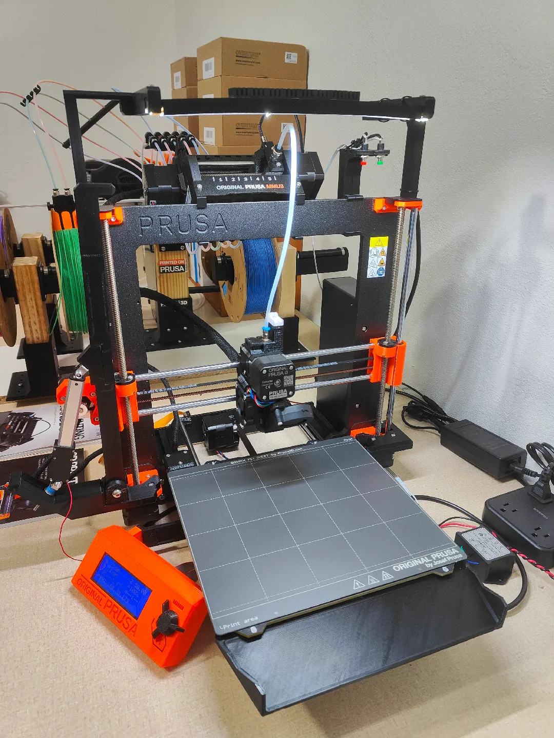
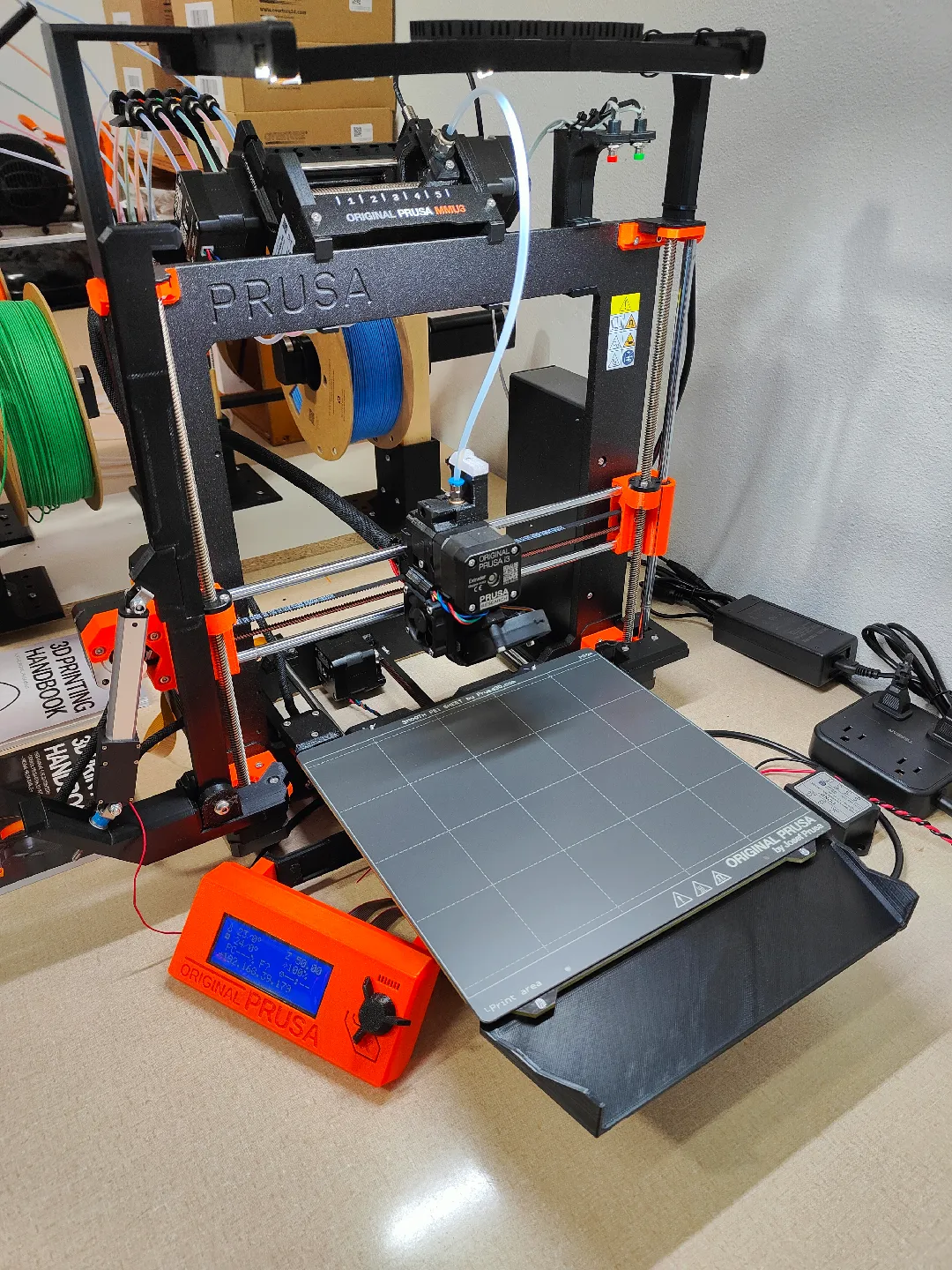
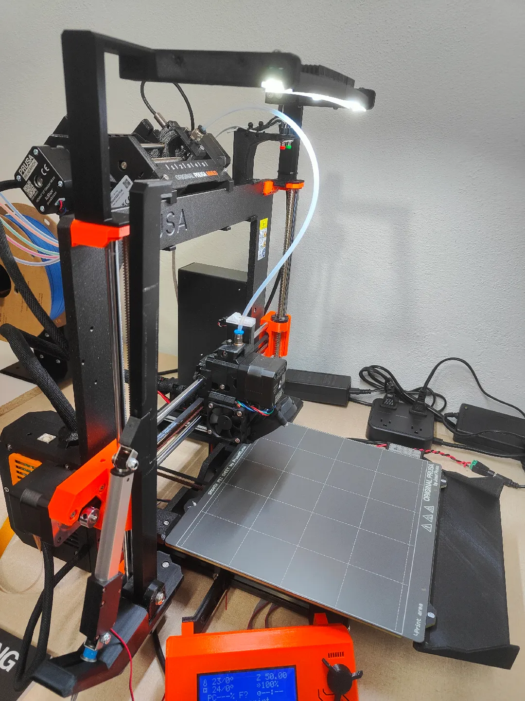
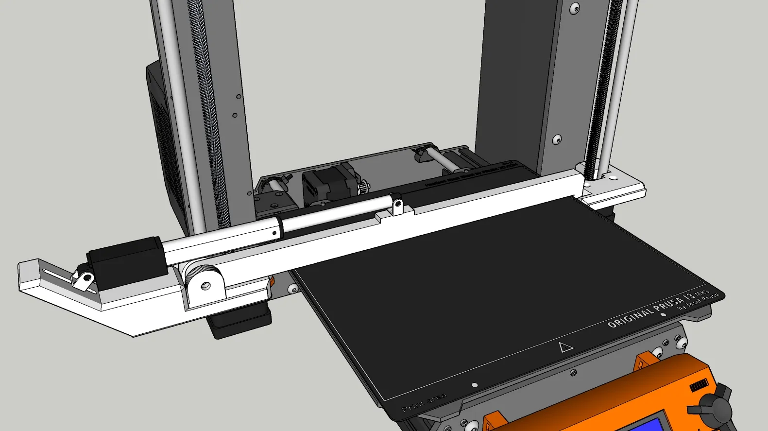
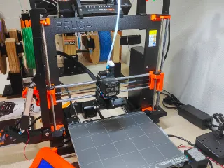
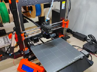
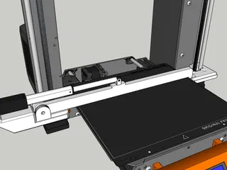
A Top-Down redesign of the Original belt driven "Loop" automatic bed clearing system for the Prusa MK3S/+ (May fit others, Not sure)
Inspired by the original, but shaky on weather or not it had enough clearance to function well long-term with the MMU3, I wanted to clear the belting away up top, and take a more electronic approach.
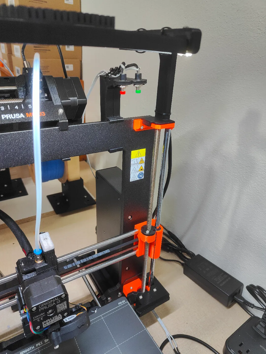
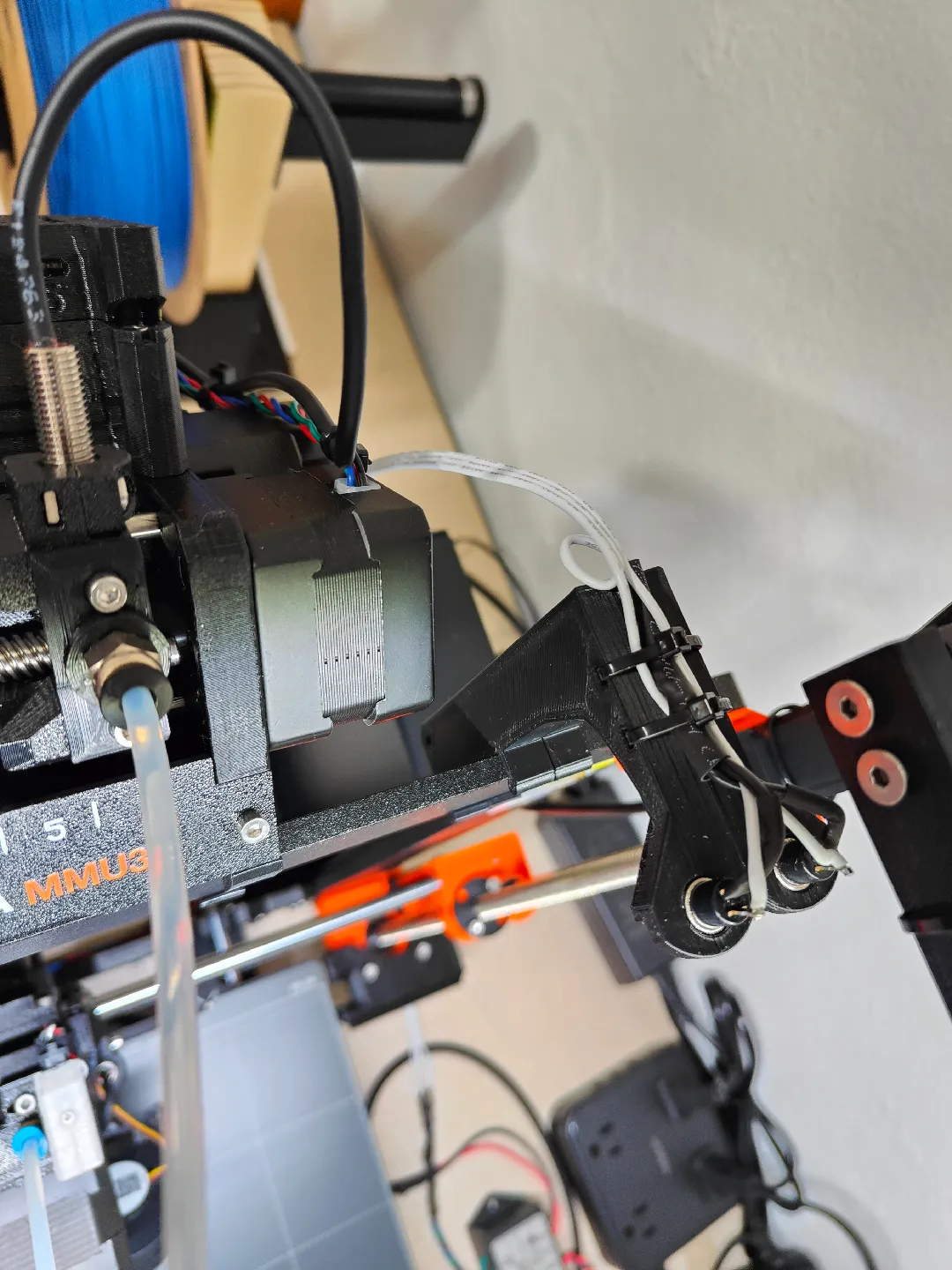
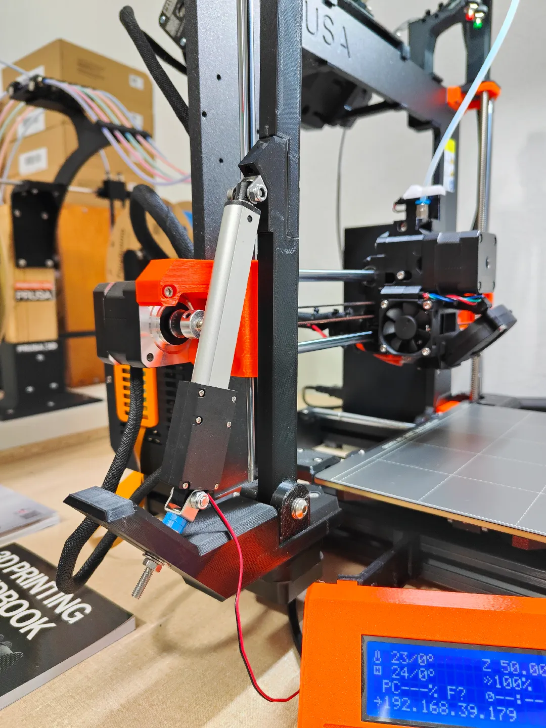
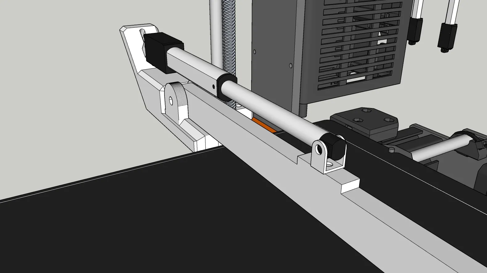
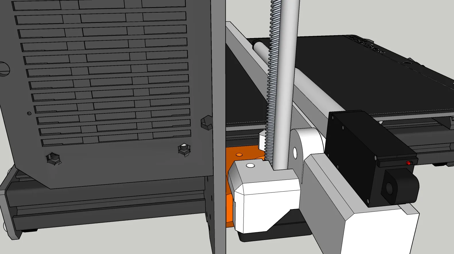
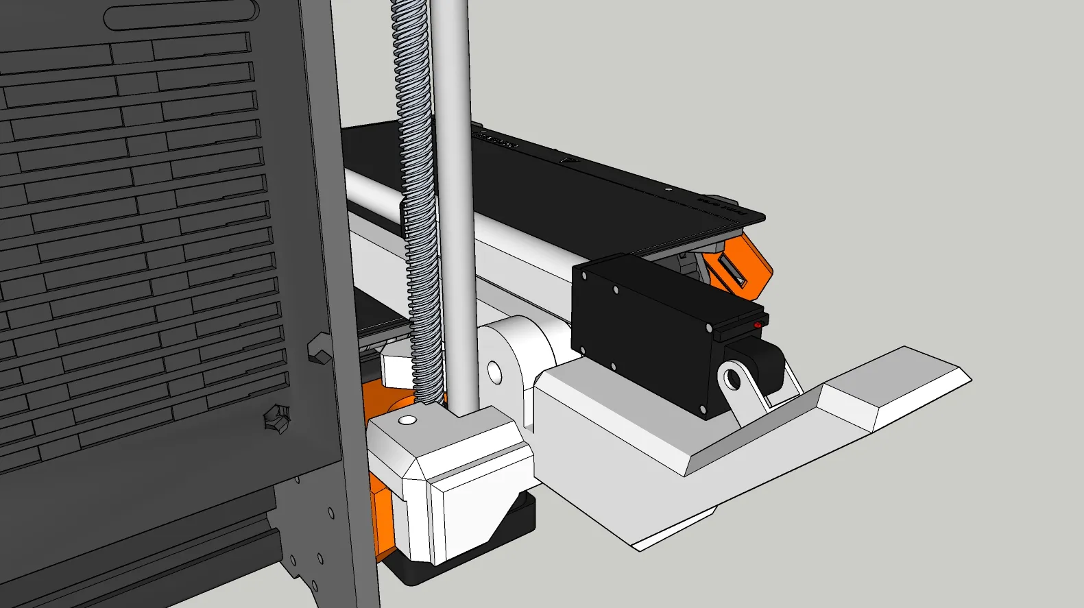
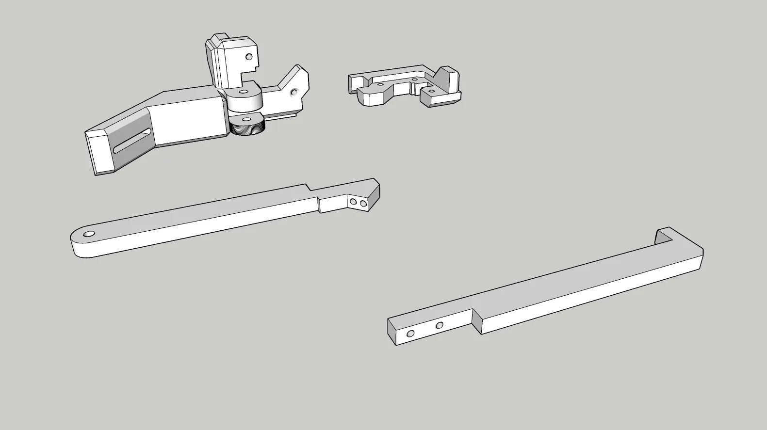
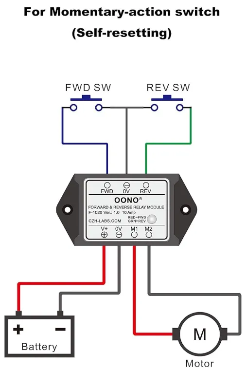
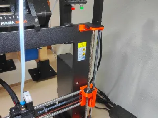
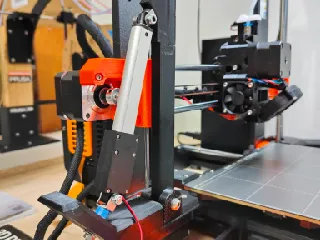
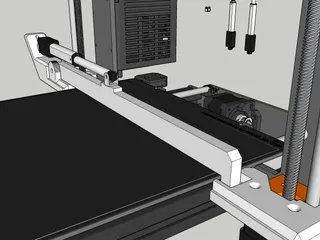
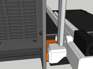
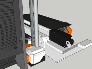
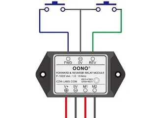
This method uses a bracket mounted 75mm Micro Linear Actuator and a forward and reverse relay, paired with 2 momentary mountable push buttons to replace the X carriage lever design of the original.
At this time, this unit is considered in alpha, and no significant testing beyond initial function has been done. But it does appear to function. Further part removal testing is needed to verify strength of arm.
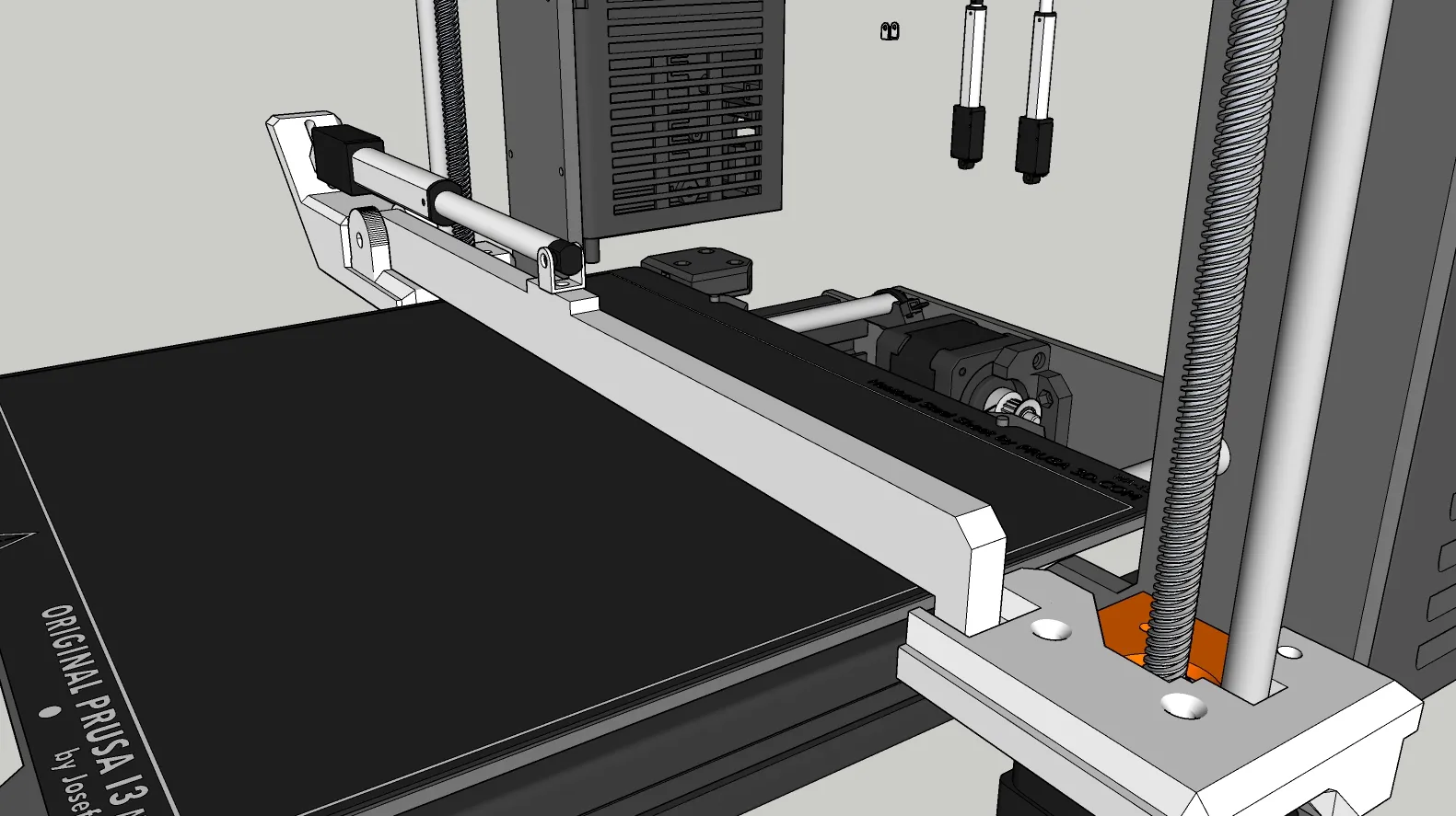
ALL drawings and design drafts have been included for maximum remixing. All drawing was done in Sketchup Pro 2024/25
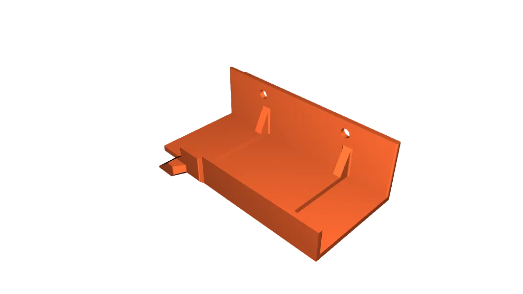
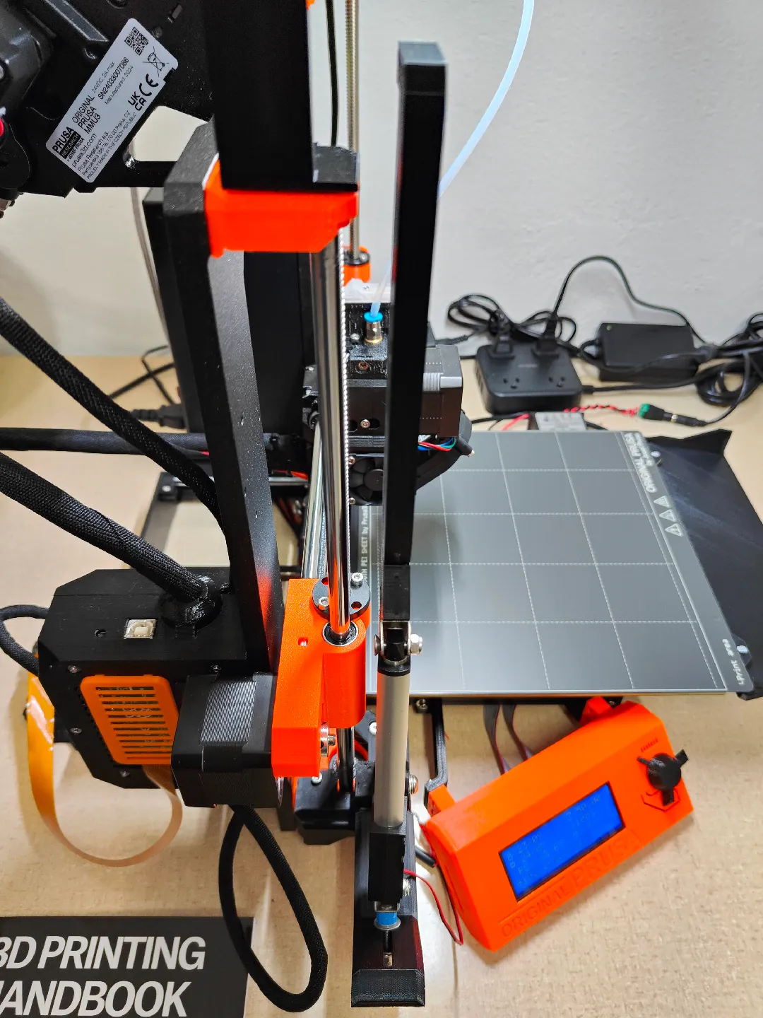
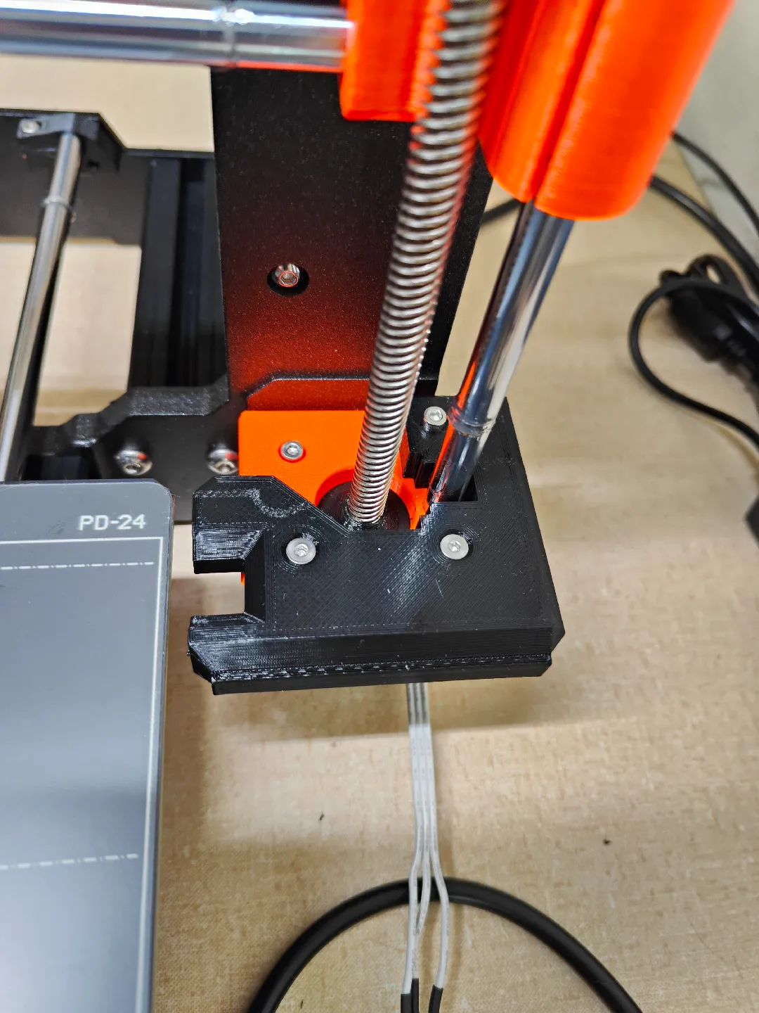
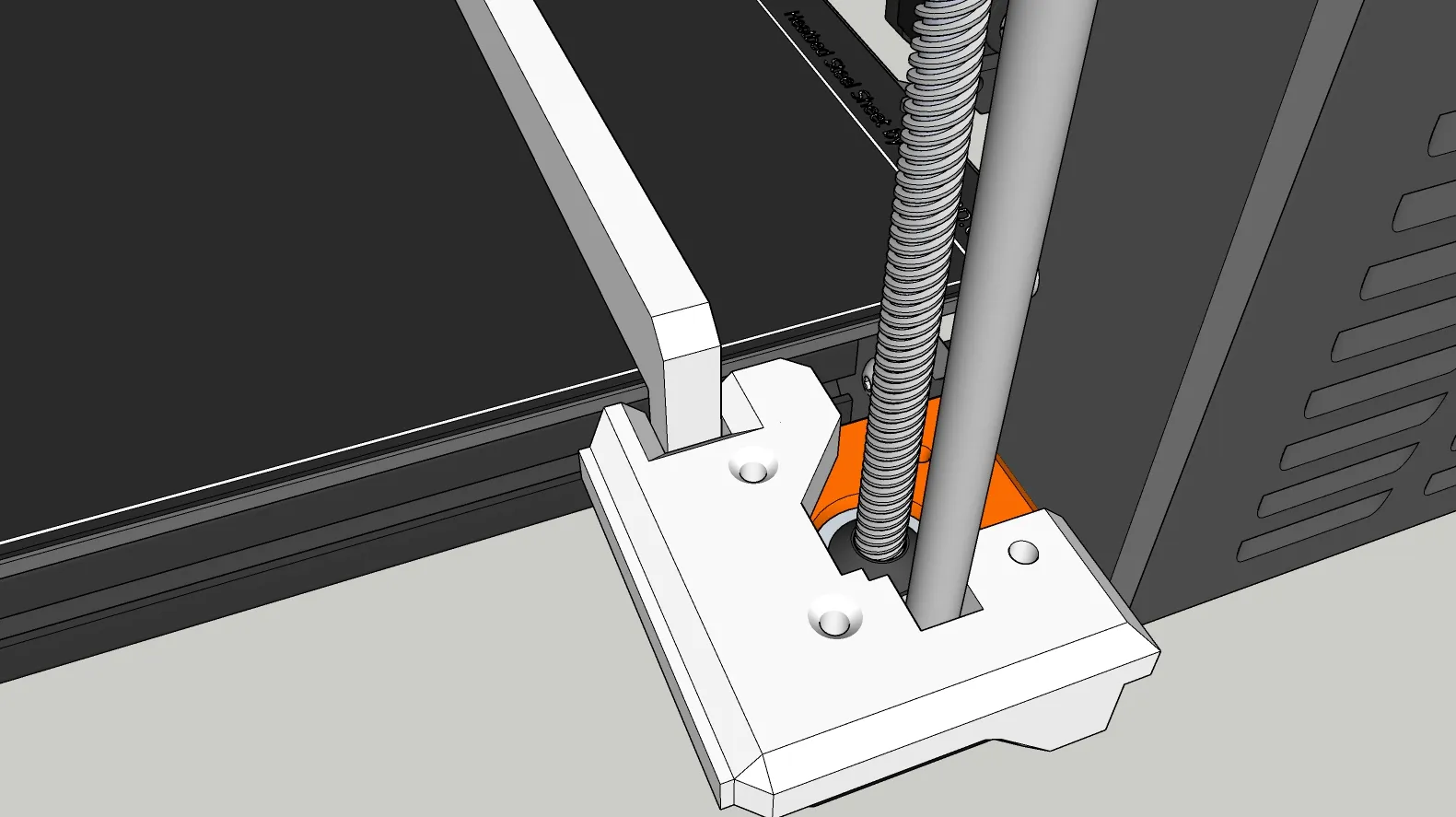
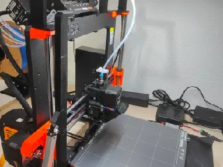
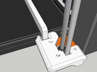
The design is pretty straight forward. Adjustability for Actuators is done with spacers, at the base of the arm. The arm should be attached first, with the fully deployed actuator mounted on top of the arm FIRST. All adjustment should be done in the DOWN position. If you attach with actuator closed, it may be positioned to far in towards the arm, and break off the arms mount point or damage the actuator when its fully deployed. In the DOWN position, we want it to sit comfortably, about a mm or 2 off the bed surface. You CAN allow it to touch the bed. But it CANNOT be pushing down on the bed. It must rest with little to no resistance on the bed surface. Use spacers at the back of the Actuator to get this adjusted until that is so.
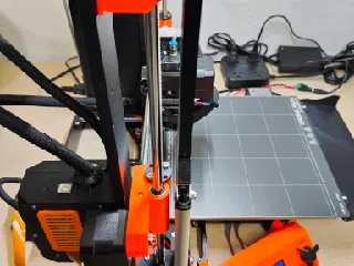
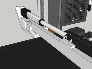
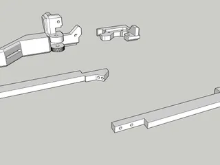
The removal ARM, should be GLUED and SCREWED together for max strength. Or it may break in the middle on larger parts.
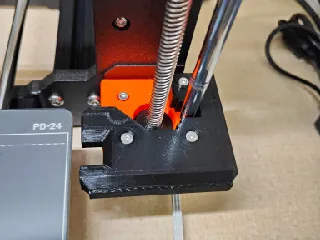
I used a hot-set brass insert on the BACK of the removal arm pivot point to catch the screw that acts as the pivot for the arm to ride on. There isn't much room back there to run a screw in from that side, as the linear rod is right next to it. The hole size could be reduced, and a screw threaded directly into the plastic to take the place of the brass insert. I'll try to get that done in a few days and add that part as an Alt for the Arm base.
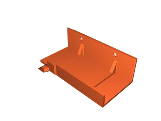
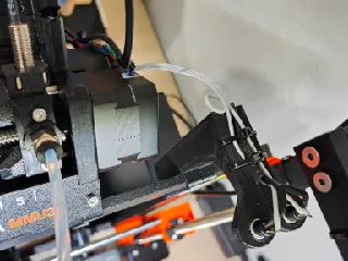
I have included Pierro55's Original ejector blade, the clip on version from his Discord (In testing), as well as his Bed mechanical covers to prevent things from falling into the belt path.
STRONGLY recommend clip on ejector blade and screw on blade, be printed in a high temp material. PLA is NOT RECOMMENDED. As it will make contact with the heatbed, and may sag. Potentially jamming the y-axis and damaging the printer.
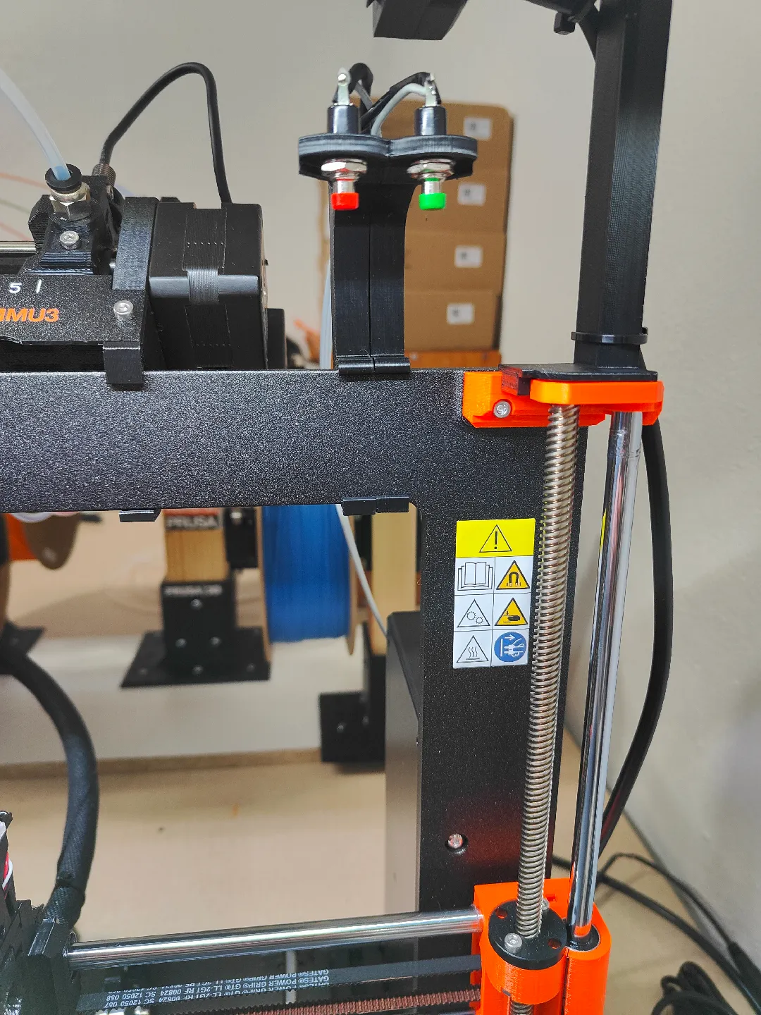
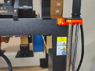
Button mounts should be positioned to sit directly under the print head @ x244(Green button/deploy), and x228(Red Button/retract) They should be triggered at 208Z height.
To ensure this, Please use the following LED Filament sensor mod: https://www.printables.com/model/653244-led-state-indicator-in-a-clear-chimney-cap-for-the
You don't have to do the LED mod, just use the Cap they provide to get the exact spacing I used. (Not sure if this is the same for a non-MMU3 Version of the MK3S+, needs verified.)
If not the end gcode can be modified to the new positions.
Demo gcode attached to this listing, is what to use in your STOP/END PRINT GCODE to get the removal sequence added to your printers function. You are simply telling it to get into position, press a button for 10 seconds, let go of the button, move to the other button, wipe off the finished print, move up and press the other button for 10 seconds, then coming to rest at the middle of the bed to await more prints.
; Position Xcarriage to press button and lower arm into place
Also found below:
G28 W ; home without ABL
G1 Y212 X244 Z10 F7000 ; move axis into position
G1 Z208 F1500 ; raise Z-axis to push Green button (Lower Arm)
G4 S10 ; wait 10 seconds for arm to lower
G1 Z200 F1500 ; lower Z-axis to release Green button (So relay won't overheat)
M907 Y800 X800 ; increase Y+X-motor current temporarily
G1 X228 F800 ; move X-axis under Red button
; wiggle motion
G1 Y-4 F2500 ; move Y-axis
G1 Y210 F20000 ; move Y-axis
G28 Y ;home Y to knock off lose objects
G28 Y ;home Y to knock off lose objects
G28 Y ;home Y to knock off lose objects
G1 Y-4 ; move Y-axis
G1 Y155 ; move Y-axis
; retract arm, put x carriage back down
G1 Z208 F1500 ; raise Z-axis to push Red button (Raise Arm)
G4 S10 ; wait 10 seconds for arm to raise
G1 Z200 F1500 ; lower Z-axis to release Red button (So relay won't overheat)
M907 Y540 X540 ;reset Y+X-motor current
G1 Z50 F1000 ; lower Z-axis
G1 X125 Y212 F10000 ; move X-axis
;--------------------------------------
M84 ; disable motors
;------------------------------------------------------------------------------------------------------------
NEEDED PARTS:
x1 Actuator @ 75mm
x1 Auto reverse relay module
x1 Pack pack of momentary push buttons
M-Hardware (To be listed), Brass hot set insert (To be listed), and Glue for the Arm.
Please let me know if you have questions in the comments. Happy to help how I can!
HAPPY PRINTING! ;-D
Tags
Model origin
The author remixed this model.

Differences of the remix compared to the original
This version of loop replaces the belts and X carriage lever, with a linear actuator to make additional clearance at the top for an MMU3. A redesigned LED bar is included, to create the clearance needed for MMU3 + Loop-Elec. This is a top-down redesign, using the premise of the original. It does NOT require any dismantling of the printer itself. Just swapping out a few screws to longer units on the Z motor mounts at the base. Everything else clips on.


