Versa Wheel

Description
PDFThis project is about developing and building a tabletop wheel for ceramic use (commonly known as banding wheel). Along with printing parts, it needs some basic hardware and two wood sheets. It can also be used for any kind of wheel system.
You can also visit project's git repository here.
In the Description you will find Bill of Materials, Tools needed, 3d Print instructions, Assembly instructions and finally how to do modifications to fit your needs. Let's start!
Versa Wheel Features
- Handles heavy forces of different directions on the spinning wheel using two bearings fixed in a 3d printed rotor.
- It is an easily modifiable construction for universal use with materials of any size (Universal Modular Design)
- Needs of minimum standard and inexpensive materials, along with basic tools
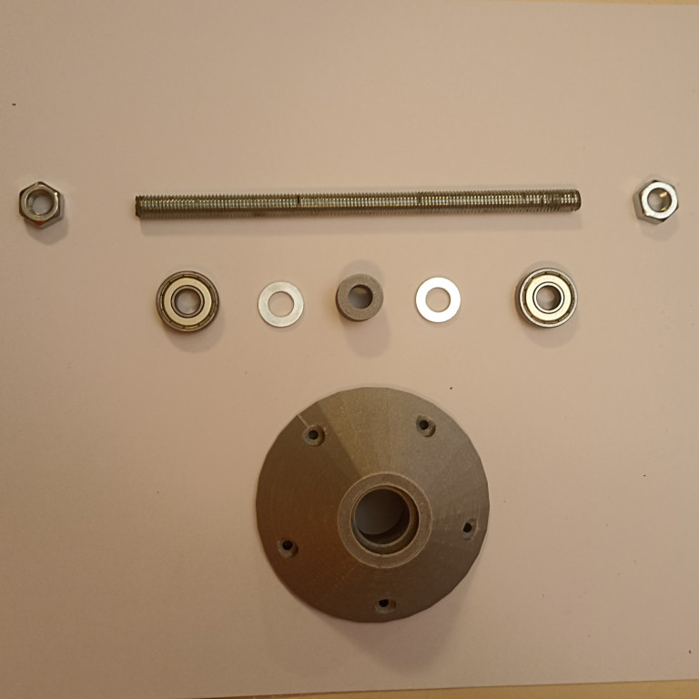
Bill Of Materials
| Item No | Part Name | Description | Quantity | Cost |
| 1 | Bearing | 6000ZZ (10mm Bore, 26mm OD) | 2 | 1.6 € |
| 2 | Threaded Rod | M10, ~100 mm length | 1 | 1 € |
| 3 | Hex Nuts | M10 | 4 | 0.5 € |
| 4 | Washers small | M10, 20mm OD | 2 | 0.2 € |
| 5 | Washer large | M10, >20mm OD | 1 | 0.1 € |
| 6 | Plywood | ~220 X 220 mm, width 10-20 mm | 2 | 5 € |
| 7 | Wood screws | ~20mm length)0 | 10 | 1 € |
| 8 | Filament | 140 gr | 1 | 4 € |
Refer to the Documentation for using hardware with different specifications.
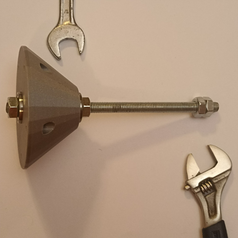
Tools
For constructing Versa Wheel, along with materials you will need the following tools:
- Two Wrench 17mm for Nuts of M10 system (They is specifically used to tighten M10 system nuts securely)
- Screwdriver (for screws on the Wood Sheets)
- Drill
- C-clamp (for testing, sawing and working)
- Marker (For marking cutting lines for accurate sawing)
- Handsaw or Jigsaw
- Sandpaper (corse) (for last touches)
Time
When you will have a complete kit with 3d printed parts and hardware, you will need about 60 minutes in assembling and 30 minutes for cutting the wood (total 90 minutes). That is the total assembling time.
3d Printing can take some boring time to complete. For this reason, 'calibration.stl' is made: a small 3d print piece that should be ready in 15-30 minutes and help you verify your hardware, before going into the final 3d printing. In this time, you can read and understand this documentation.
3D Printing
3d print parts are set for a 10mm system of threaded rods, nuts and bearings. You could get away with directly printing these .stl files if your hardware parts closely match those described in the bill of materials. We strongly advice though to first print the calibration part and test hardware fitting as described in the next section.
If you take the safest path, the typical 3d printing workflow involves opening setup.scad, tweaking Customizer parameters there if needed, selecting different part using PART parameter, export to .stl and print the parts one by one. (this is described in the end of this manual) Follow along this manual and start with calibration part to test hardware fitting with bearing and screws. Next, move on to the rest of the parts.
Large scale modifications like using a different hardware sytem of 8 or 12mm is no different. Make sure you measure your hardware parts with caution and update all relevant parameters in setup.scad.
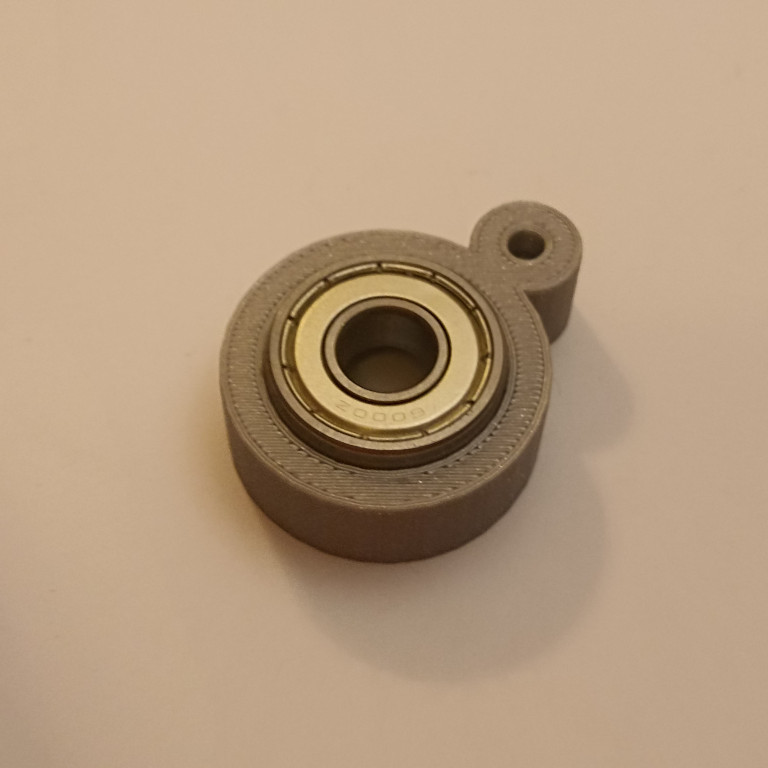
Calibration test part
Printing calibration.stl can ensure your hardware (bearing and screws) fits perfect to your 3d printed parts.
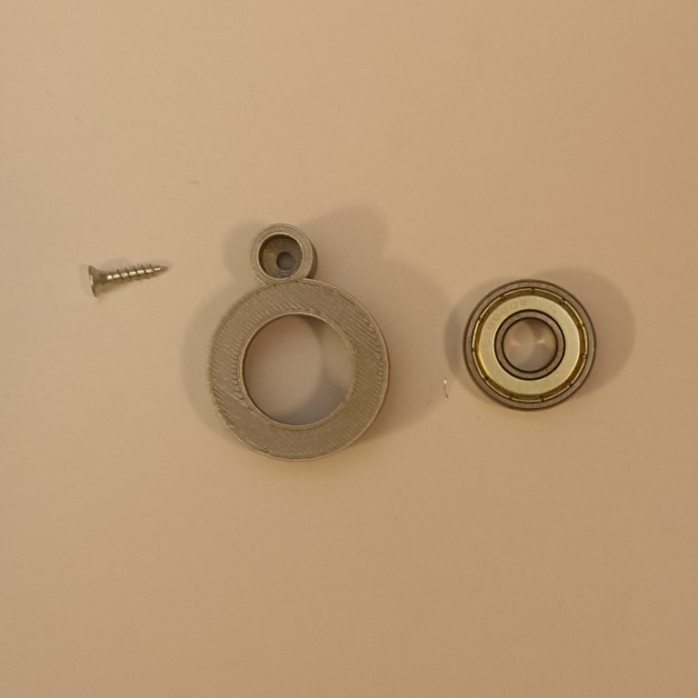
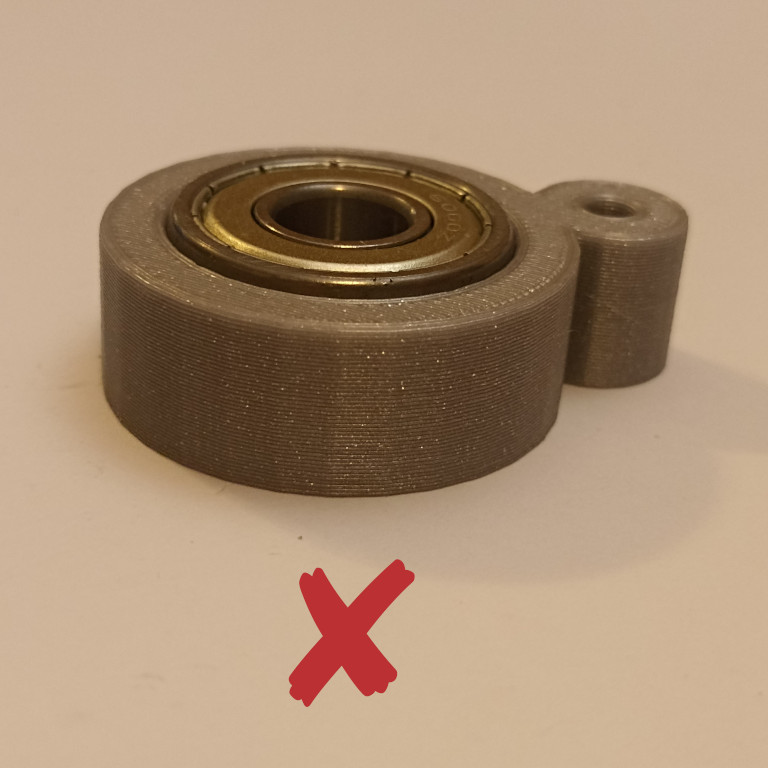
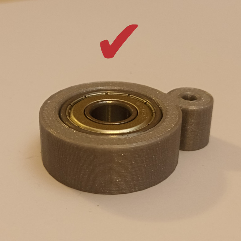
Fit the bearing in. Maybe the first layer needs to be sanded to fix elephant foot. Make sure it has tight contact and its top surface levels with the calibration part.
 |  |  |
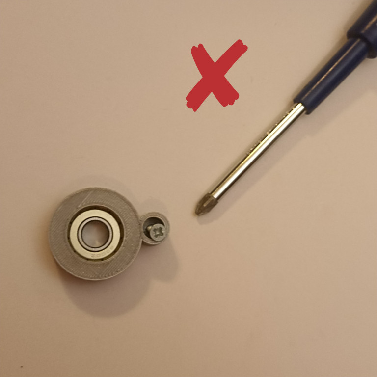
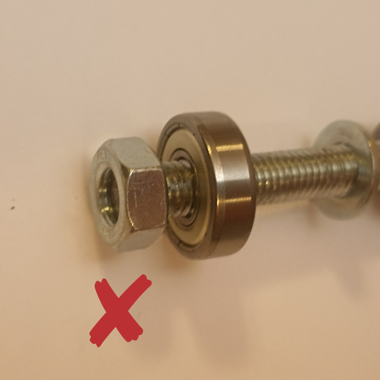
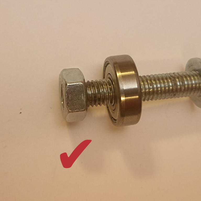
Fit the screw in the small opening. It should run freely through the hole and not tightly screw inside it:
 | 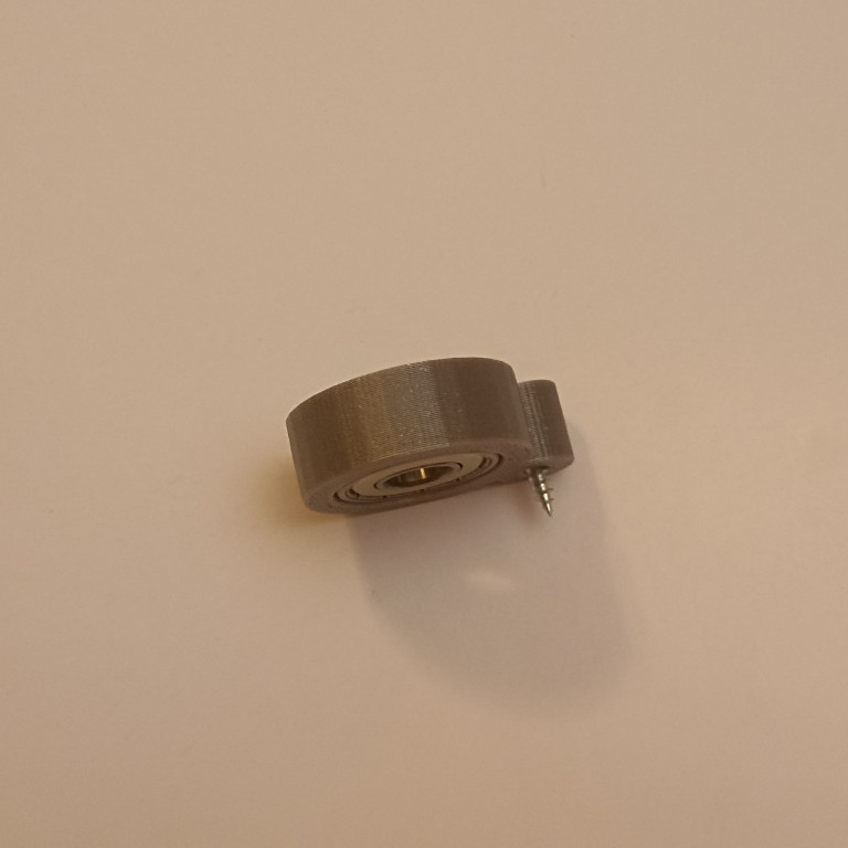 |
For troubleshoting see documentation.
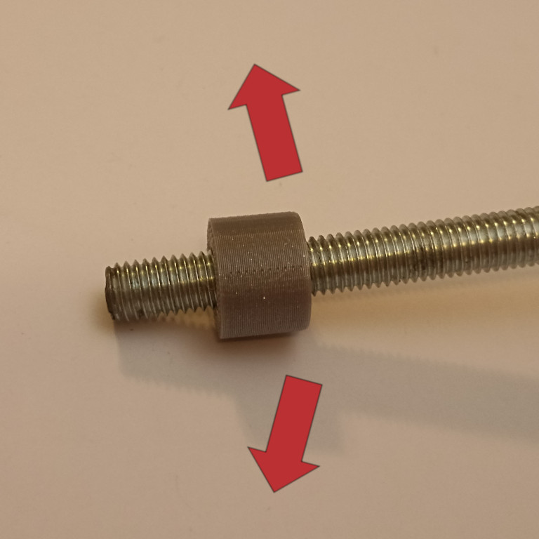
Distancer
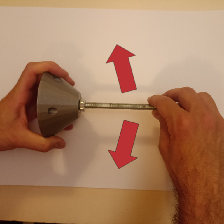
This part should have a loose fit around the threaded rod and run on it easily, but with no tolerances. Print it with 100% infill slicer setting.
rotor.stl and stator.stl
Assuming that hardware matching verification with 'calibration.stl' part went well, move forward with the main parts. Render to .stl and print stator and rotor parts. They may look the same, but they have differences. Mark them, so you don't get them mixed up.
Slicing configuration:
- infill = 20%
- enable support
- perimeters = 2
For any modifications in 3d printing parts, check the final part of this manual.
Assembling
Rotor Assembly
Rotor is the rotating part of the Versa Wheel.
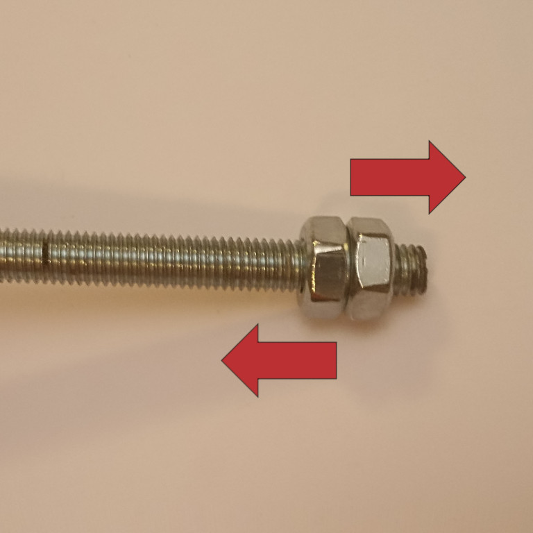
For assembly, first put bearing, washers, nuts and printing parts in line as in the following picture. Start by pulling on the Threaded Rod: the nut, the bearing, the small washer, the distancer (3d print part), the small washer:
 | 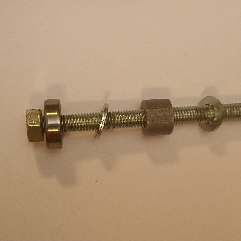 |
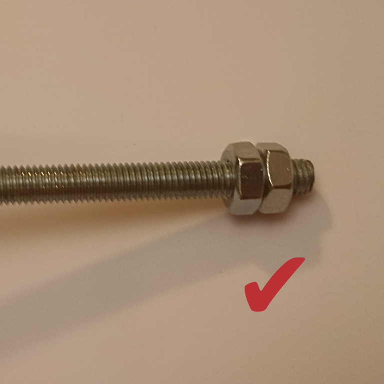
Take care so the starting nut is level with the rod's face.
 |  |  |
Pass the other side of the rod inside the rotor. Afterwards, first pass the small washer, then the second bearing, the final nut and tighten by hand:
 |  |  |
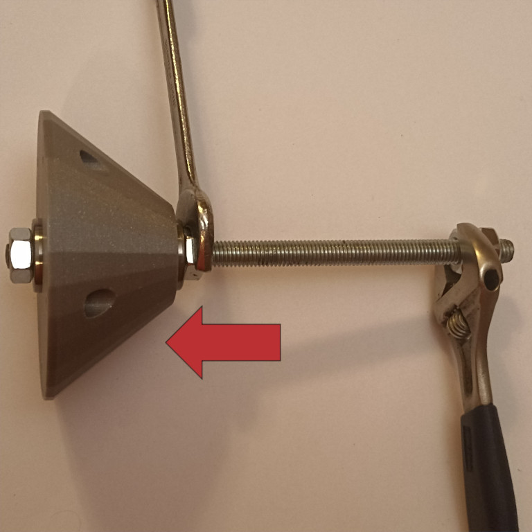
You should now tighten the assembled parts together properly. Use two additional nuts to make a lock nut at the other end of the rod. Tighten them together with two wrenches.
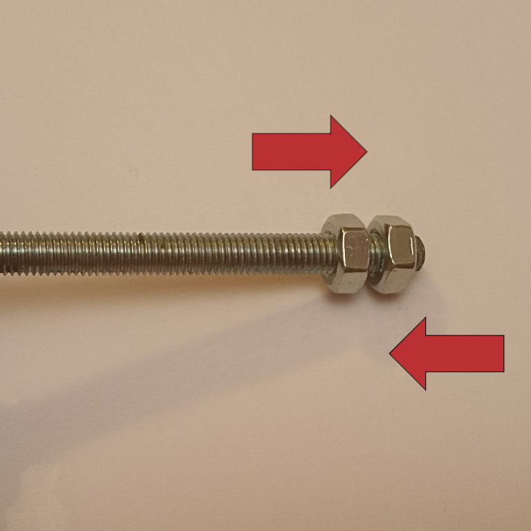 |  |
Holding the lock nut with one wrench (make sure you grip the right one), tighten the other one against the rotor. Tighten well but do not overtighten. Remember, there is the plastic distancer part hanging in the middle of the rod that gets all the pressure. You will notice that the left side nut slowly gets inside the rotor. At the end, you should be able to rotate the rod but not untighten the nuts using bare hands.
 |  |  |
Release the lock nuts and remove them:
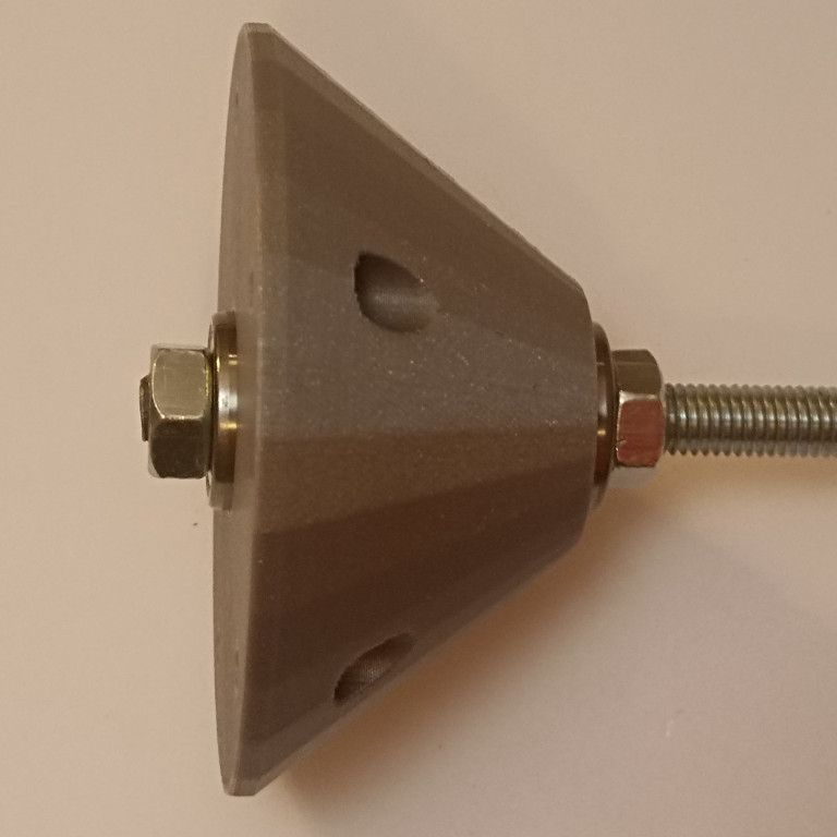
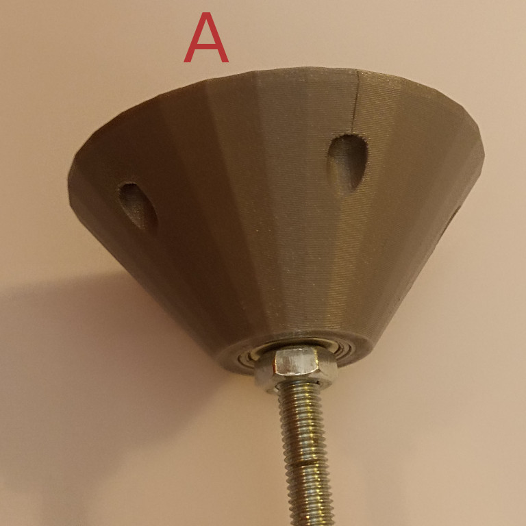
Here is the Rotor after assembly:
 | 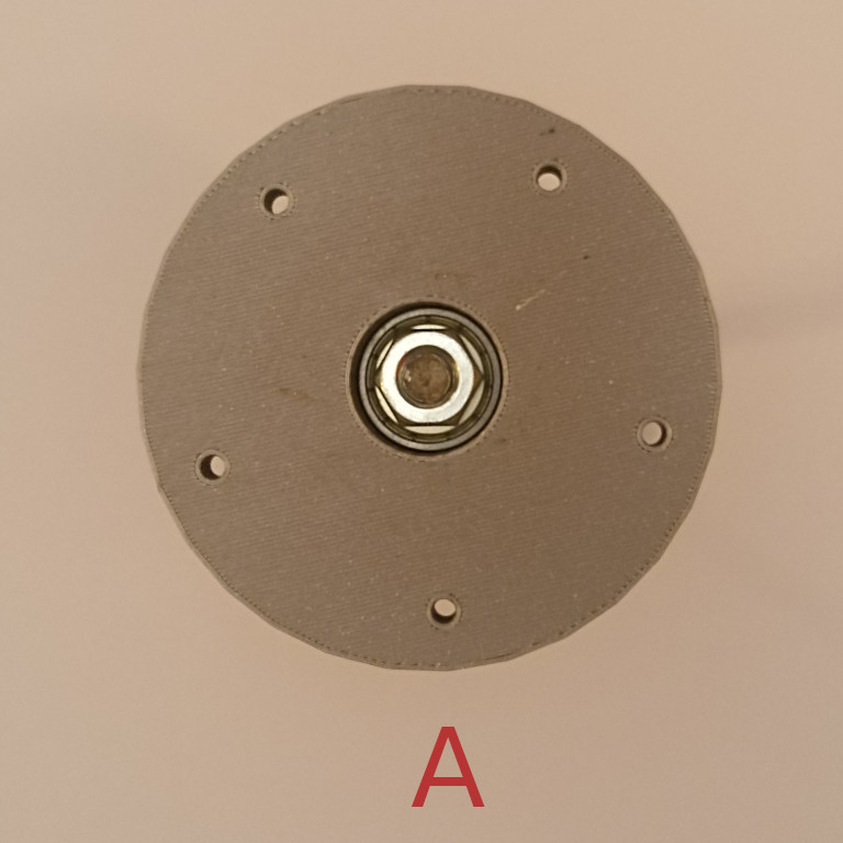 |
Wood sheets and finaly assembly
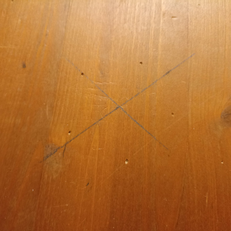
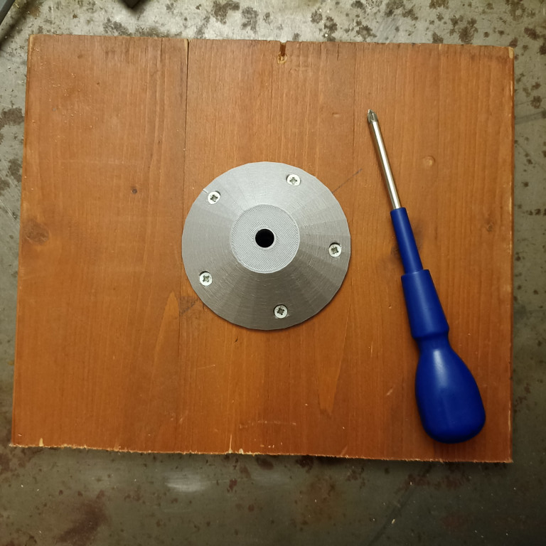
You need two wooded (preferably plywood) sheets for the Stator (base) and Rotor (rotating part) parts respectively. Start with a rectanguler shape and make a cross with two diagonals to spot the center.
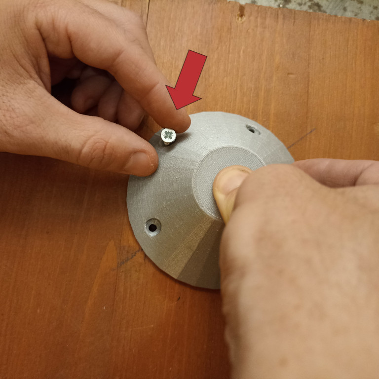
Attach the stator (in the following photo it seems has the same color and seems identical to rotor, but they are truly different) to the wooded sheet. This is the base that will eventually get fixed on your workbench. Put a nut in the slot of the 3d printed part. Then, turn it over and put in on the center of the wooden sheet:
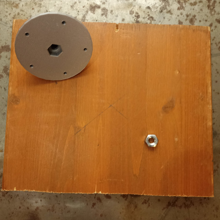 |  |  |
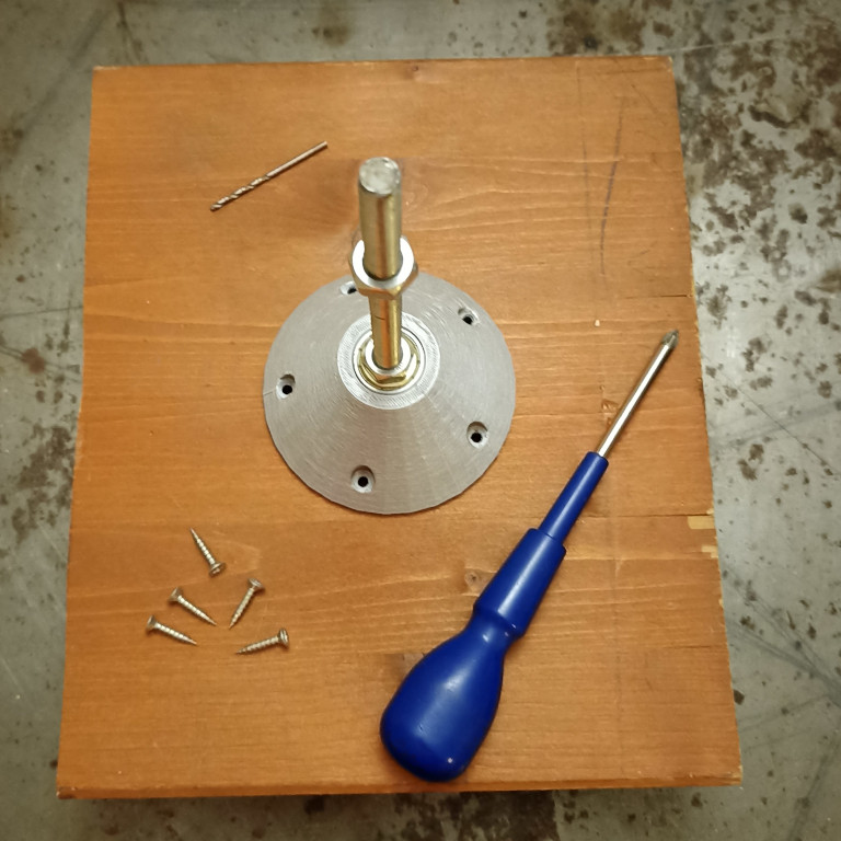
Push a screw to mark the positions of the holes. The 3d printed part should be in a fixed position until you mark all the holes.
Make holes using a drill (slightly smaller than the screw diameter). Some wood sheets, do not need drilling (plywood sheet will be fine without drilling).
 |  | 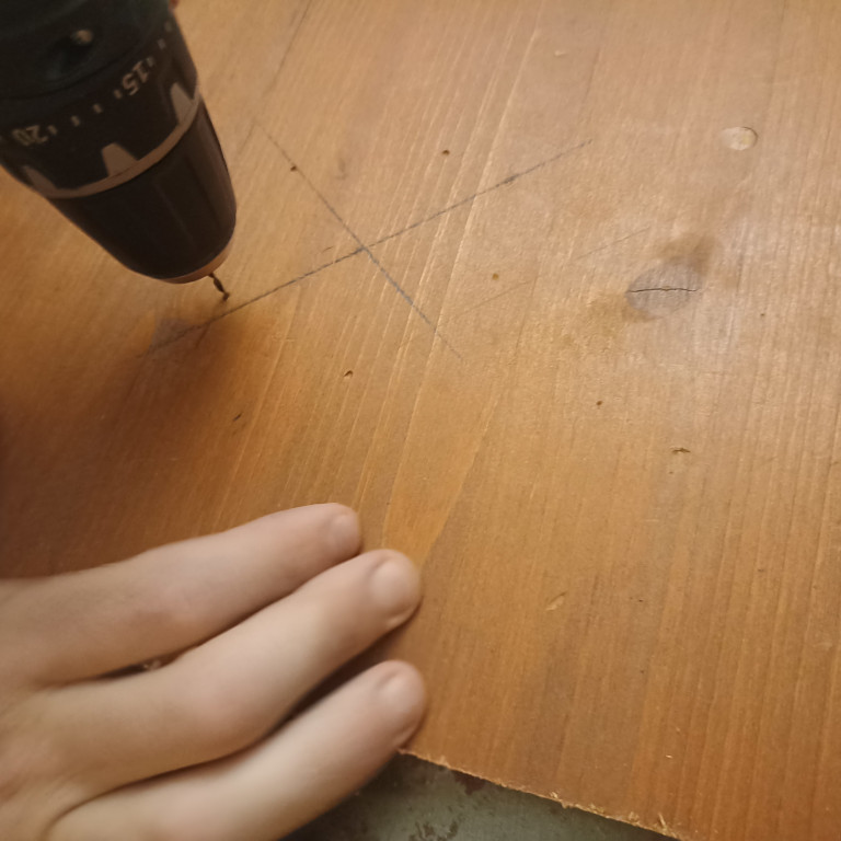 | 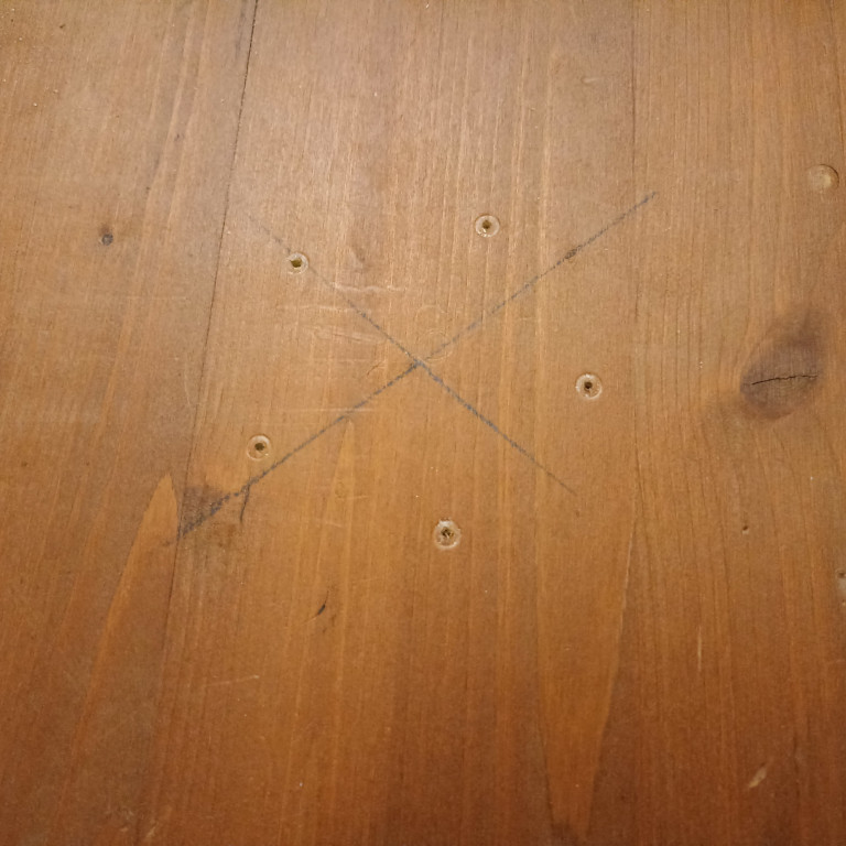 |
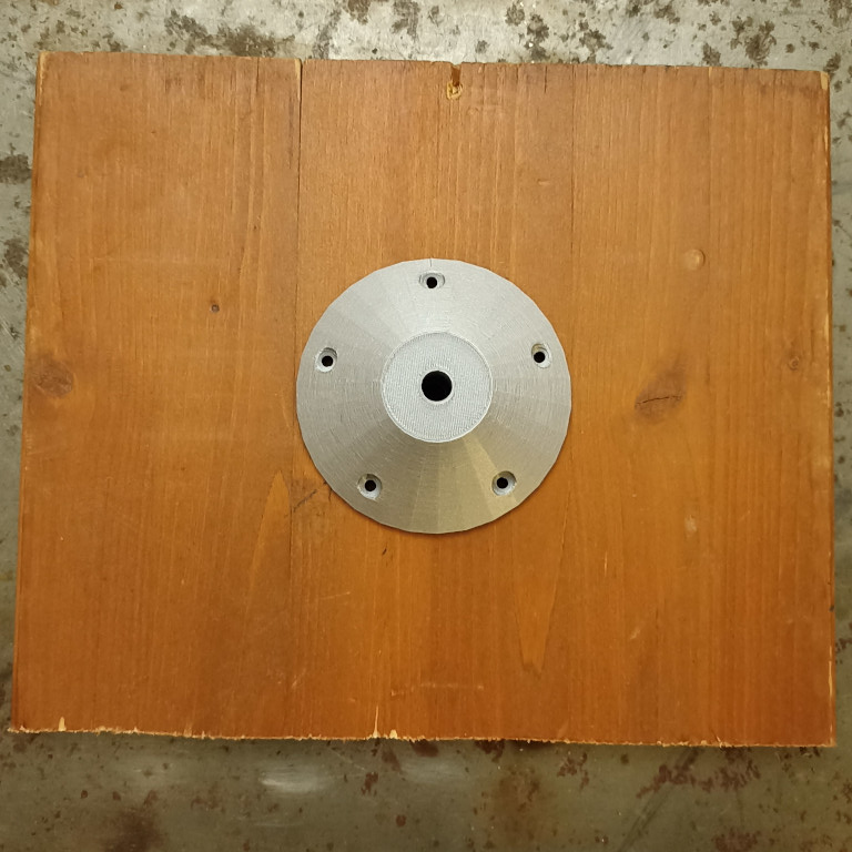
Place the 3d printed part in the center and put the screws in the marked holes. Start with screws in opposite positions. Tighten so that the 3d printed part is snuggly attached to the wooden sheet.
 |  |
Follow the same method for the rotor to drill holes and attach to the second wooden sheet. You can you a circular wood sheet if you can find the center of its circle. As before, it is important to have the 3d printed part snuggly attached to the sheet:
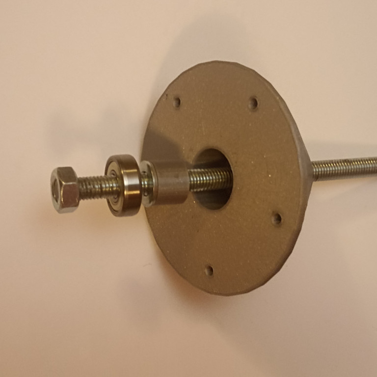
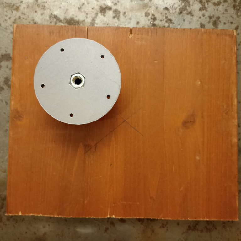
Back to the stator part, install a nut and the big washer as shown.
Let the threaded rod pass through the Stator. Tighten or push it through until its threads catch up on the (embedded) nut at the other side. Keep tightening carefully until the rod reaches the wooden sheet. You'll feel some kind of resistance when this happens. If you cannot do this with bare hands use a pair of pliers and a piece of cloth to avoid damaging the threads of the rod.
After tightening the rod in the stator part, tighten the last nut. Note, you 'll need perform these last steps once more, after disassembling (once).
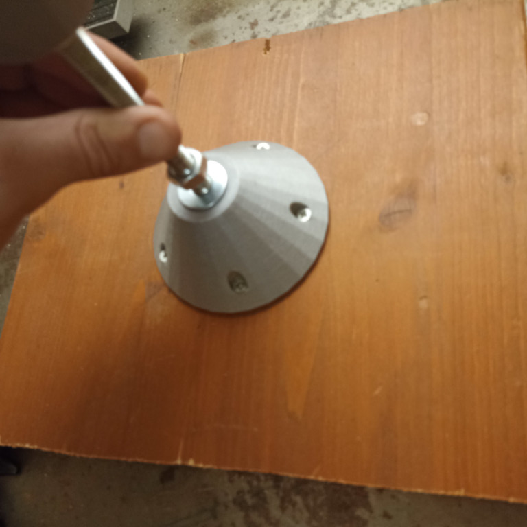 | 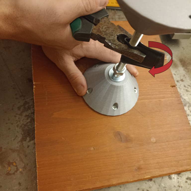 |  |
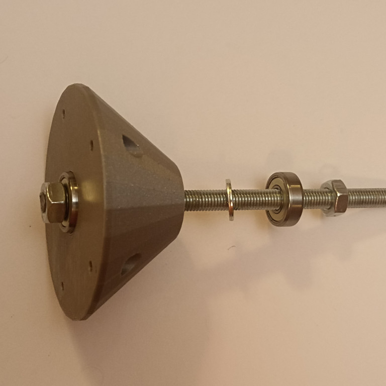
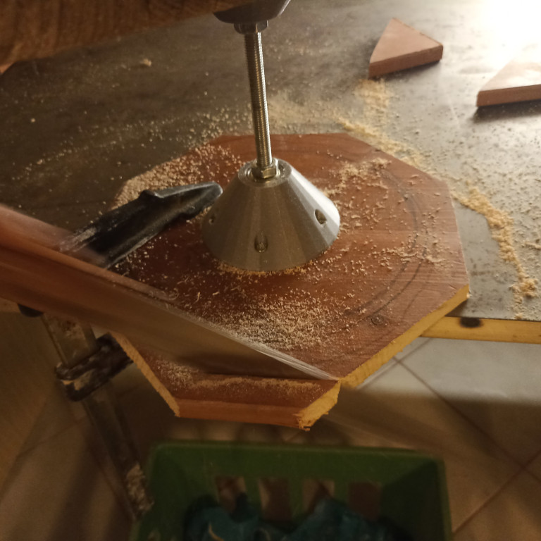
Here is how your banding wheel should look like at this point. In the photo it's fixed on a table with two C-clamps making it steady for the next move.
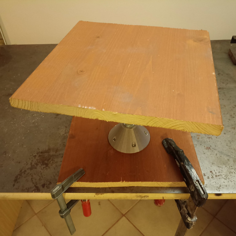
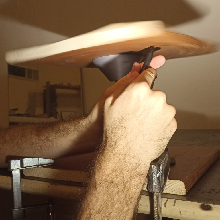
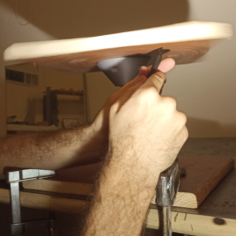
You'll now need to mark a circle on the wooden sheet. Hold the marker as steady as possible and give a spin to the rotor by hand. As the top sheet rotates mark a circle with the marker.
 |  |
After marking the circle, disassembly the stator. Release the last nut and the threaded rod just by doing the last moves in the opposite way.
Hand tight, you're almost done...
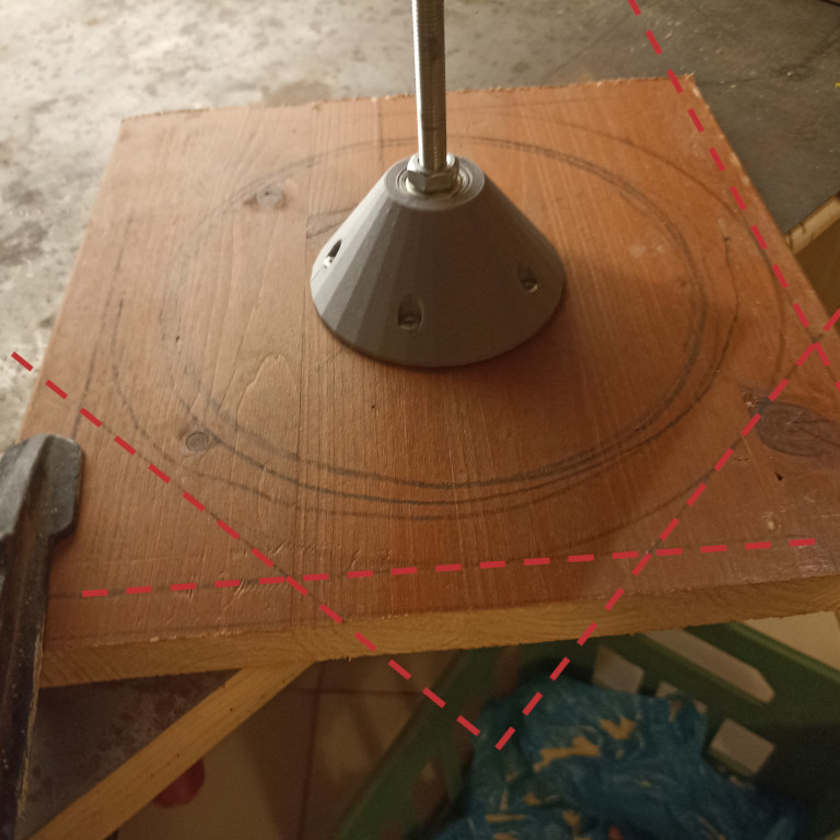
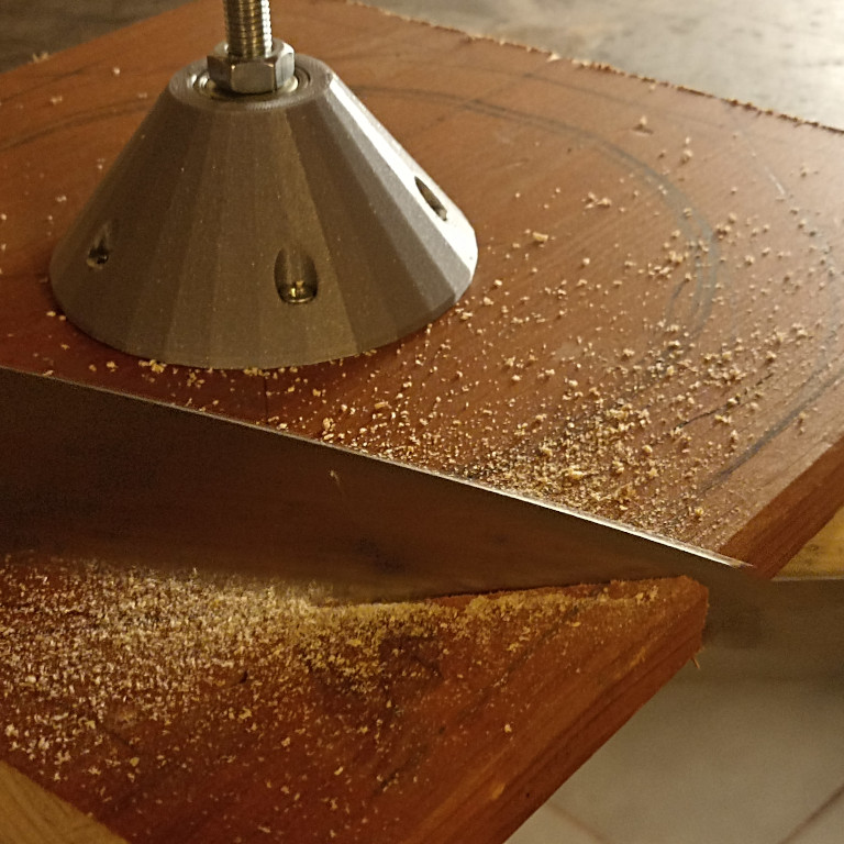
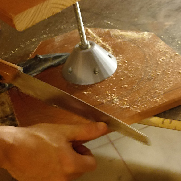
Now, you have to cut the wooden sheet of the Rotor. There are two ways to do this. Use a hand jigsaw to cut the sheet following the circle line. Or, mark tangent lines and then cut straight parts off using a hand saw. We took the second option by cutting off four corners resulting in an octagon shape as showed in the first picture.
Cut the corners off with a hand saw following your marked line. You'll notice in the picture that we didn't disassamble the stator. You don't need to suffer as we did.
 |  |  |  |
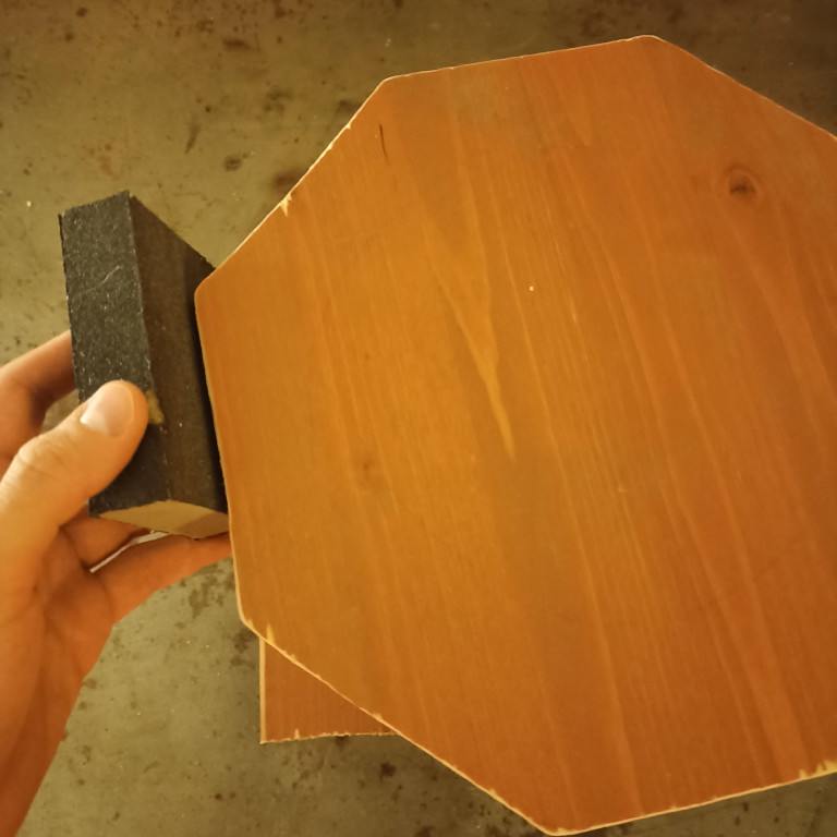
Having the wooden sheet cun in shape, assemble the stator again using last steps. Use a sandpaper to finish the edges.
Congratulations! Share your thoughts and hoping that you are satisfied with results over time.
Modifing 3d printing parts using openSCAD
In some cases, you will need to modify the 3d printed parts.
- Hardware bearings and screw don't fit in the 'calibration' part
- The materials are different from what this manual suggests
- You need a bigger or smaller banding wheel
For these cases, there are source '.scad' files to modify and render new '.stl' files. You will need OpenSCAD application for that. You can download it here.
Start OpenSCAD and open the file 'printables/setup.scad'. Make sure the window 'customizer' is runnig as you can see in it the following picture.
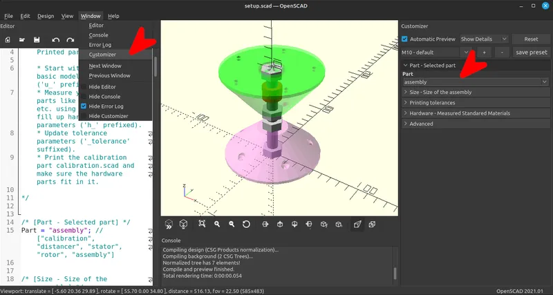
Customizer is a complete guide to modify this design. It has five tabs as you can see in the screenshot above:
- Part - which 3d print part you need
- Size - Size of the apparatus
- Tolerances - 3d print tolerances
- Hardware - materials you have measured
- Advanced - for advanced editing
Customizer - Part
Choose 'assembly' while making changes, so you can preview the complete design.
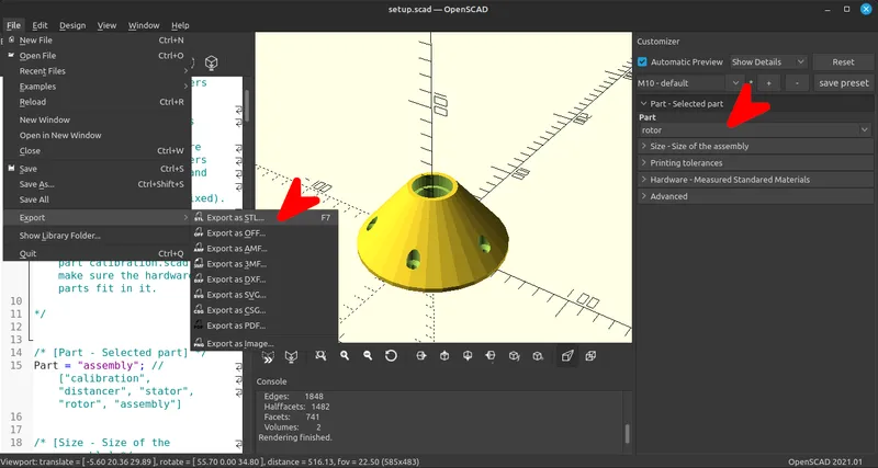
When you are ready with your new design, you will need to render new set of '.stl' files. Choose the file you will need, starting with 'calibration' to see if your design is good. Then, move on to 'distancer', 'stator', 'rotor'. After chosing the part you need, go to 'Design' --> 'Render' (F6). Wait to hear the ringing bell and choose 'File' --> 'Export' --> 'Export as stl' (F7).
Customizer - Size of the apparatus
You can easily make modifications for a smaller or bigger banding wheel. Open 'Size' tab and give the dimentions you need. Before choosing dimentions keep in mind that:
- Maximum dimentions of Stator and Rotor ensure good adhension to the wood sheets.
- In big diameters you will need more screws.
- In big diameters you will need bigger Threaded Rod (and bearings, nuts, washers)
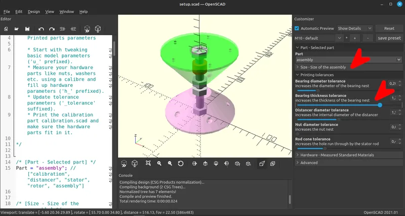
Customizer - Tolerances - 3d print tolerances
'calibration' is a small 3d printed part that has opening with exactly the same dimensions with the main parts. This part allows testing whether standard components (like bearing and screw) fit correctly in the printed parts. You can print a small part for the test with no waste of time and materials. This practice also helps cope with differences in 3d printer environments.
In customizer, open the tab 'Tolerances - 3d print tolerances' and increase or decrease following these rules:
- Bearing diameter tolerance = is added to the diameter of bearing
- Bearing thickness tolerance = is added to the width of bearing
- Distancer diameter tolerance = is added to the diameter of Threaded Rod (only for distancer 3d printed part)
- Nut diameter tolerance = is added to the diameter of the nut
- Rod cone tolerance = is added to the diameter of Threaded Rod
If the tolerances are properly set, the parts will match with hardware of differente size (ex for other size of bearings).
Common mistakes when you use calibration part:
The bearing doesn't fit
You have to first check if you have elephant foot. If your printer cannot face it, then you need to sand elephant foot. If it stil doesn't fit, then you should modify 'Bearing diameter tolerance'. Increase if by 0.30 and print calibration again.
The bearing is not fixed but it moves
You first need to check bearing's dimentions. If are right, then try reducing 'Bearing diameter tolerance' by 0.3.
The bearing fits fine, but is overhangs or is too submerged
Check bearings width first. Then, if it overhangs, increase 'Bearing thickness tolerance' by 0.3, or if it too submerged, reduce it by 0.3. Try again with calibration.
The screw is not correct
The screw has to be able to fit the calibration part without screwing. Measure screw's dimention. If it stil doesn't go through easily, increase 'Bolt diam' (customizers hardware tab) by 0.3 and print another round of calibration.
Customizer - Hardware - Standard Components that You Have Measured
It is important to know the dimensions of the materials you are using, such as nuts, washers, bearings, and threaded rods. While standardized materials are available commercially, the design can work with any material as long as you know the exact measurements, taken with a caliper. In the customizer, open the tab 'Hardware - Materials You Have Measured' and input their dimensions.
Threaded Rod
- outer diameter = 'Rod diam'
The outer diameter of the Threaded Rod includes the threading
Nuts
- distance between opposite sides = 'Nut diam'
- thickness = 'Nut thickness'
Bearings
- outer diameter = 'Bearing diam'
- thickness = 'Bearing thickness'
The thickness of the bearing should be measured on along the inner piece
Washers (only the small ones)
- outer diameter = 'Washer diam'
- thickness = 'Washer thickness'
NOTE: The large washer does not play a role in this section.
Wood Screws
outer diameter = 'Bolt diam'
head diameter of the screw = 'Bolt head diam'
if the screw is conical (milled), check = 'Bolt coned'
For screws shorter than the suggested ones, you can reduce the parameter Advanced/Bolt depth so that the length of the screw inside the wood + Bolt_depth equals the total length of the screw. If the screws are too large, you can simply cut them after installation.
Note, outer diameter includes the threading.
Customizer - Advanced - For Advanced Users
Distancer Tension Margin
In the rotor system, the two nuts are tightened along with the two small washers on the distancer. In the 3d printed part of the rotor, the bearings sit on two feet, which must have a little space after tightening. This variable increases this space. As the variable increases, the vertical balance of the rotor increases, as the nut-washer-bearing-distancer system moves, touching one foot or the other.
Tags
Model origin
The author marked this model as their own original creation.