xrp_fastcar: An alternative chassis for the XRP
Description
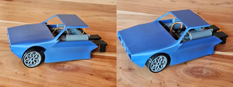
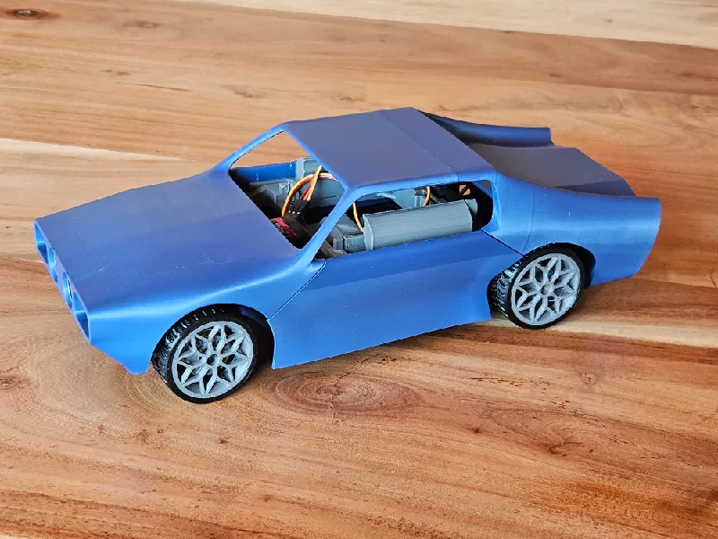
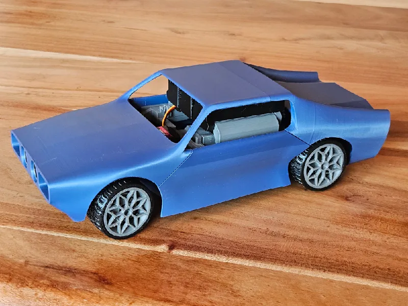
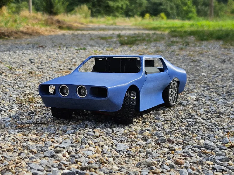
PDFThis is a full chassis replacement for the XRP kit, inspired by classic cars of the 1970s.
The chassis utilizes all the electronics found in the kit:
- Rear wheels are driven by one motor each
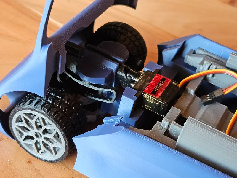
- Servo motor controls steering
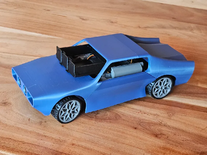
- Ultrasonic sensor for obstacle detection in the direction of travel
- Line-following sensor right behind the front wheels, facing the floor.
- Battery compartment, easily removable with no tools
- The mainboard has space in the central section of the car
You need two additional ball bearings (20x32x7mm) for the front tires.
I do not own the XRP kit, which is why I derived most of the component specific mounts from the original XRP frame.
This chassis is neither more spacious nor more expandable than the original frame. It does have inferior maneuverability and is slightly more difficult to assemble.
But the coolness factor is arguably much higher.
I personally find the kinematic model of a car much more interesting than the differential kinematic model of the original frame. The former also tends to be more relevant in control theory, as it is what is most often used in driver assistance systems and autonomous cars.
The line-following sensor coupled with the ultrasonic sensor in their respective locations make this chassis the ideal platform to prototype and test driver-assistance systems and more complex (LQ) control loops. A classical example would be a lane keeping assistant, or an emergency brake system based on obstacle detection.
Construction manual
Prepare the four tires. Required objects:
2x rim_front_outer.stl
2x tire_***.stl
2x ball bearing
2x rim_rear.stl
Choose your tire variant. Street tires recommended for the lower rolling noise. Tire stiffness can be influenced by number of parameters and infill ratio, too stiff can make the assembly tideous.
I recommend 1-2 parameters, 0-5% infill. TPU obviously.
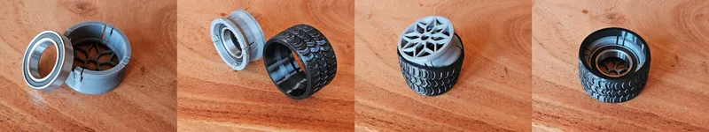
Installation on the rear rims is analogous.
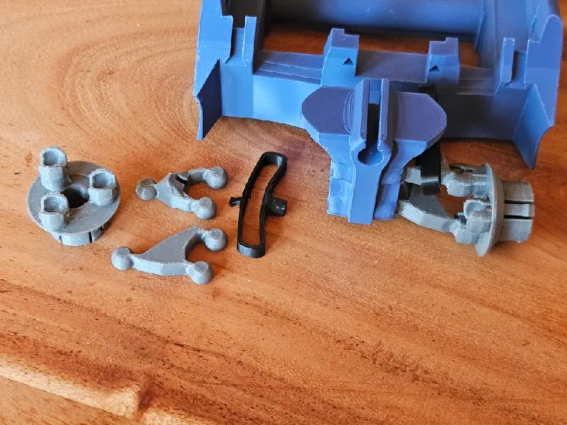
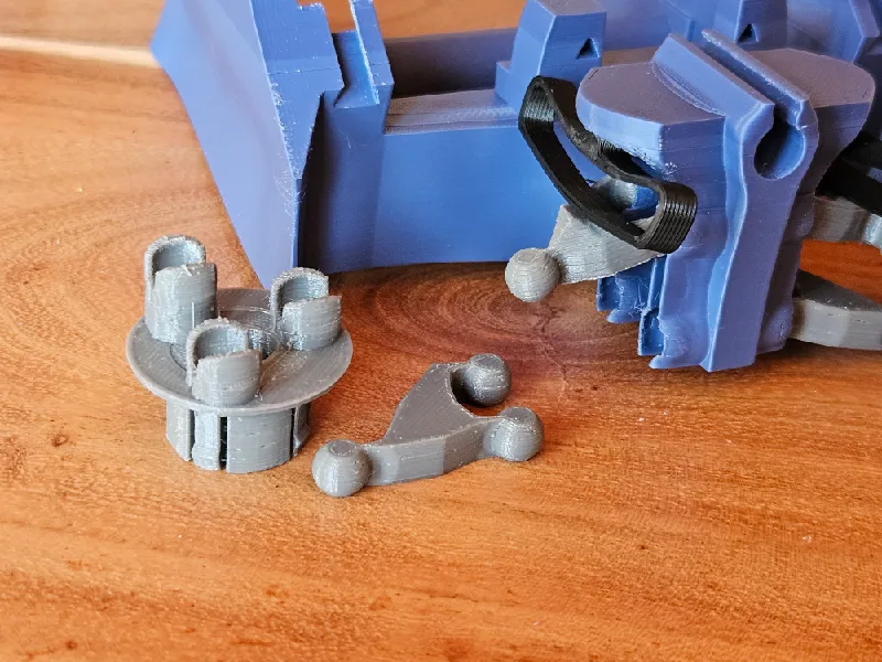
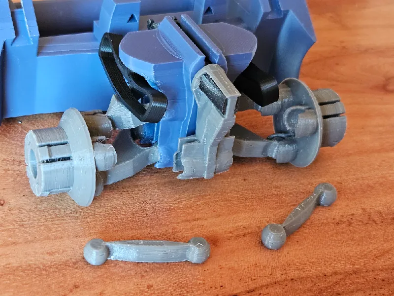
Build the front suspension. Required objects:
chassis_mid.stl
suspension_arm_lower_l/r.stl
suspension_arm_upper_l/r.stl
rim_front_inner_l/r.stl
2x spring_front.stl
Overview:
Press the spring into its designated hole in the chassis. It should be a tight pressure fit. Make sure the little latch is facing the right way.
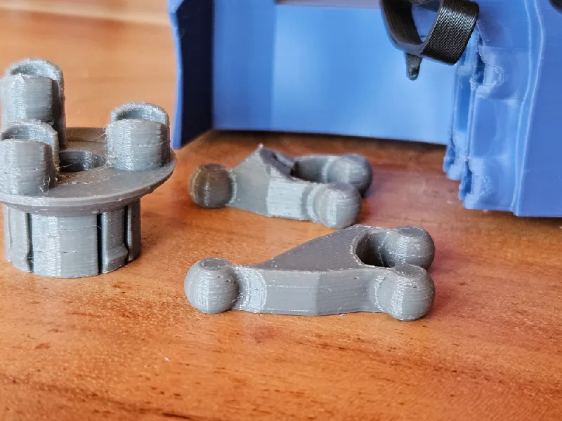
Add the upper a-arm. Insert the latch into the designated recess. The spheres should be loose but held in place firmly. if not wiggle it around until it is.
Add the lower a-arm. Make sure it is oriented correctly.
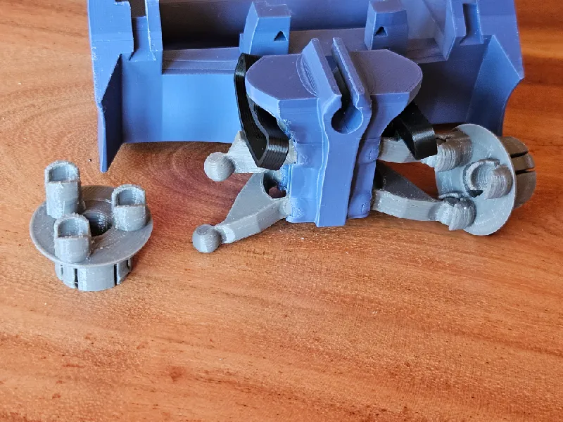
Add the inner part of the front rim. Make sure the upper a-arm is connected to the furthest extruded connector. If the slits are not oriented as shown, the rim parts might have been mixed up (left to right).
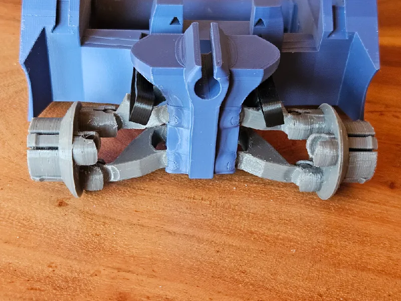
Repeat for the other side.
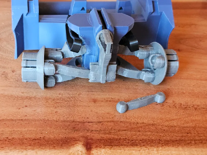
Build the steering. Required objects:
steer_axis.stl
ster_lever.stl
steer_arm_l/r.stl
Servo motor
Overview
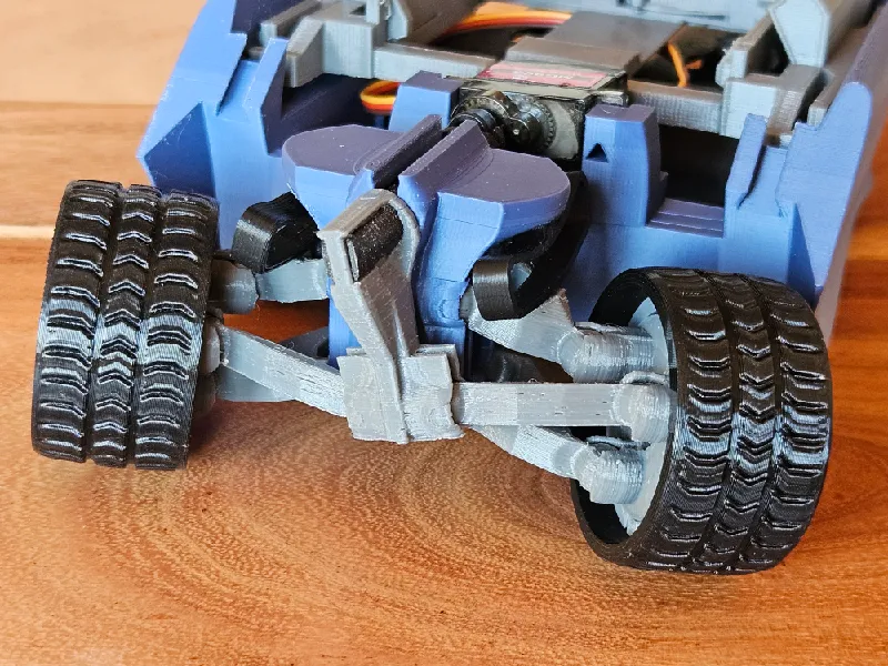
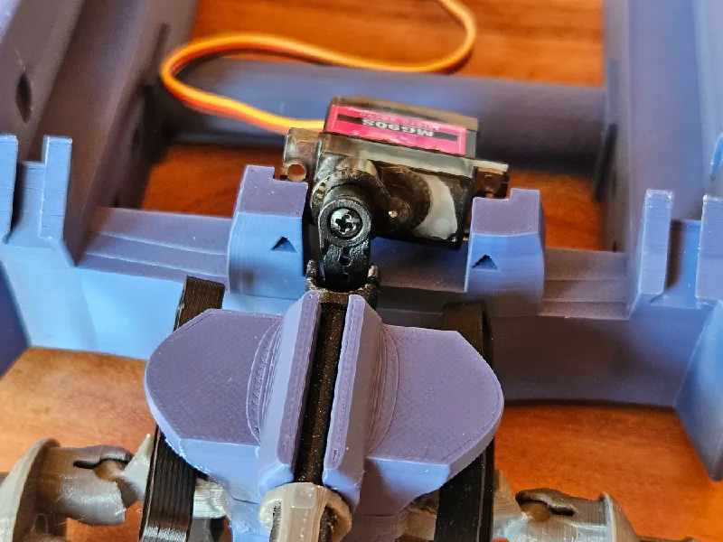
Insert the steer axis through the designated hole.

Add the steer lever. This is a pretty tight fit, might require a bit of force.
Connect the steer arms as shown.
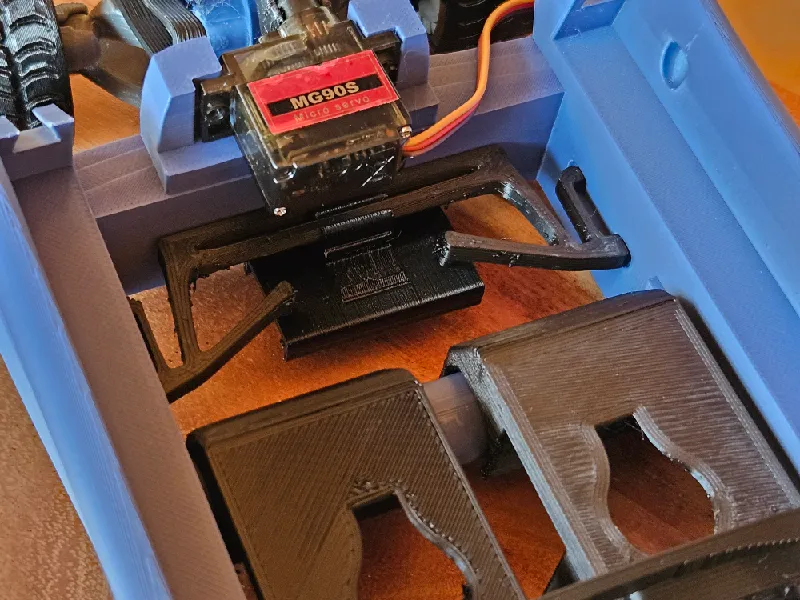
Add the servo motor to its designated spot. I have used an MG90S, which should fit the one in the xrp kit. Feel free to add screws fixing it in place left and right, although these screws are not required.
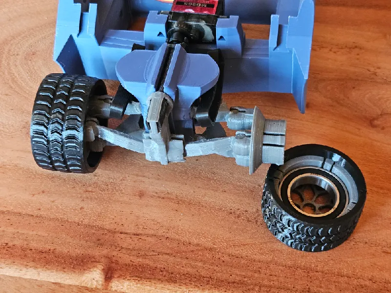
Add the tires.
Build the rear suspension. Required objects:
motorHolder_l/r.stl
spring_rear.stl
Add the motor brackets as shown.
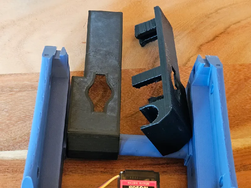
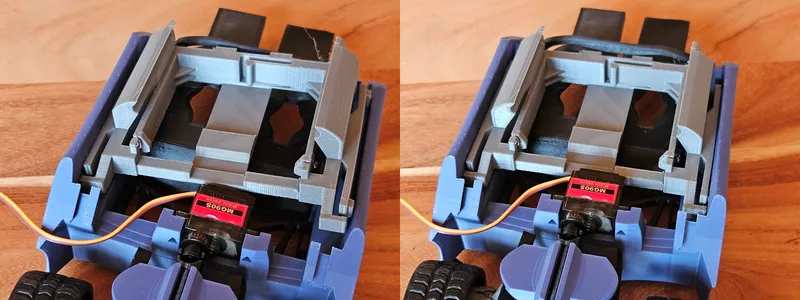
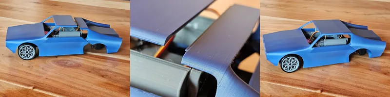
Add the rear spring. It should be bendable enough to insert both sides into the designated square hole in the chassis.
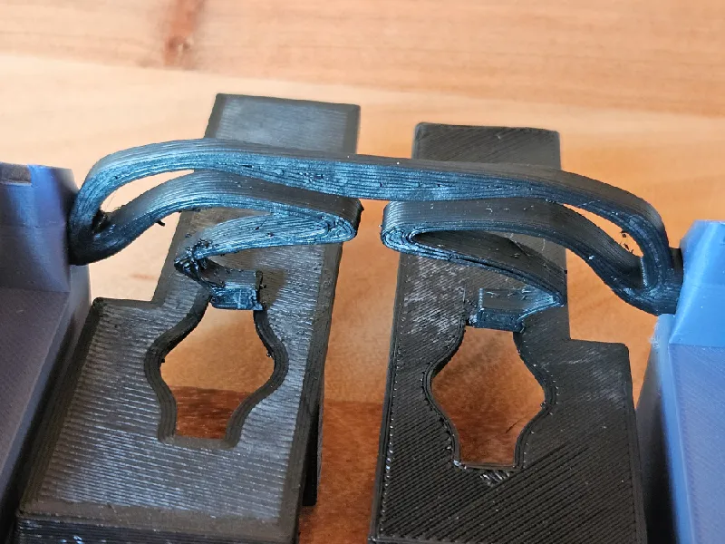
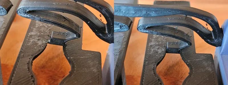
Make sure the hooks on both sides are correctly positioned, as shown in the picture.
Left is bad, right is good.
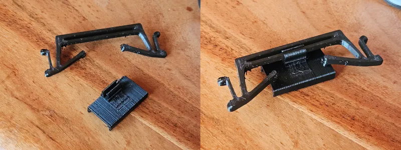
Install sensor mounts and brackets. Required objects:
mount_reflectSensorBracket.stl
Reflectance Sensor Bracket.3MF from the original XRP chassis
chassis_front.stl
mount_mainboard.stl
Ultrasonic sensor
Assemble the reflectance sensor mount as shown and install it in the mid section of the car.
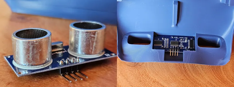
Install the ultrasonic sensor in the front section of the chassis. I have added a little bit of (transparent) tape around the cylindric part to achieve a tighter fit, as can perhaps be seen in the image.
Install the mainboard mount by first inserting one side and then sliding down the other side. This is the point where you should do most of the cabelling if you actually have the mainboard at hand.
Install sensor mounts and brackets. Required objects: The rest.
If you want to install any lights, do it now.
The chassis provides space for several 5mm standard LEDs. The inserts light_front_l/r.stl and light_rear.stl can be inserted into the chassis, or redesigned to fit other light sources or different LED arrangements. I did not install any lights on my car.
Proceed by sliding the front section of the chassis in place by lining up the two trapezoid guides left and right. The ledge below the hood will latch into the gap above the steer axis.
Slide the rear portion of the chassis in place by lining up its guides. It should click in place firmly. Make sure the stabilizing ledge of the roof is aligned with the recess in the front part, which needs to be slightly bent down for the alignment.
Add the motors with the rear tire assemblies.
Slide in the battery compartment. It will click into place.
Enjoy your fully assembled car.
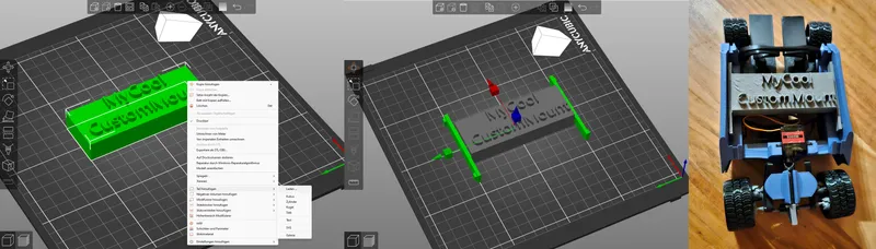
Custom mounting brackets
Should you want to create custom mounts for things, template brackets are included for the reflectance sensor and mainboard mount.
Create your custom mount, load it into your slicer, then add the respective template file (TEMPLATE_lowerMount.stl & TEMPLATE_upperMount.stl) to your design.
I have published this car in the public domain. I appreciate attribution, but I do not require it.
Do want you want with the model, as long as you have fun with it.
Tags
Model origin
The author marked this model as their own original creation.