DIY iMac Late 2014 5K monitor kit for R1811 driver board

Description
PDFTo convert my iMac Late 5K 2014 into a 5K monitor I used a Stonetasking R1811 driver board. Most of instructions here can be applied to other iMacs and other driver boards as well. Note, that my particular iMac is one with a factory VESA mount.
Highlights
- Mount for temperature controlled 80mm fan
- Mounts for R1811 board, crossovers and temperature control board
- Button panel on the rear or in VESA mount
- IR remote control holder
- IR via the existing webcam window
- Not changing the aesthetics of the iMacs frontside
- Actually, not changing much on the backside either
- Using the location of the camera for the IR receiver
- Button panel hidden in VESA mount
- I'm aware most iMacs sold don't have have this VESA mount as it was a factory-option, but maybe someone can create one that looks the same as the original Apple one
- Fan lines up with the existing ventilation holes
- Cables management via the hole for the power cable
Requirements
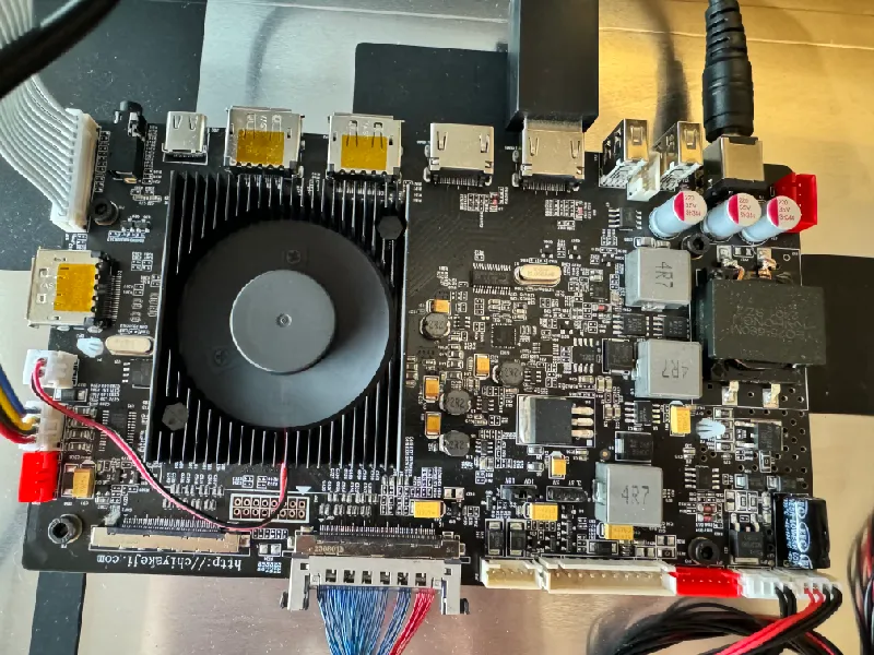
- R1811 rev. 4 driver board
- 2x YLY-8022 crossover boards
- M3 screws
- M3 inserts
- Tools
- Skills
Instructions
Preparations
- Remove everything from the iMac, except the speakers. There are instructions on the web
- Don't forget to remove the power connector too, mine was held with two screws and glue and needed some wiggling to be persuaded
- Leave the wifi antennas
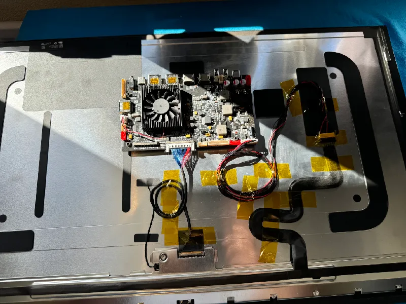
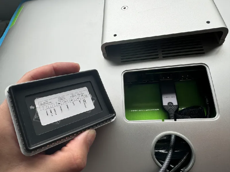
Installing the R1811 board
- I ordered the R1811 (revision 4 board) directly from https://stonetaskin.com
- Print the R1811_board mount.stl twice in PETG or ABS
- Put M3 inserts in the holes using a soldering gun
- Mount the board with screws
- Use double adhesive tape to mount the board to the LCD panel (not the aluminium casing)
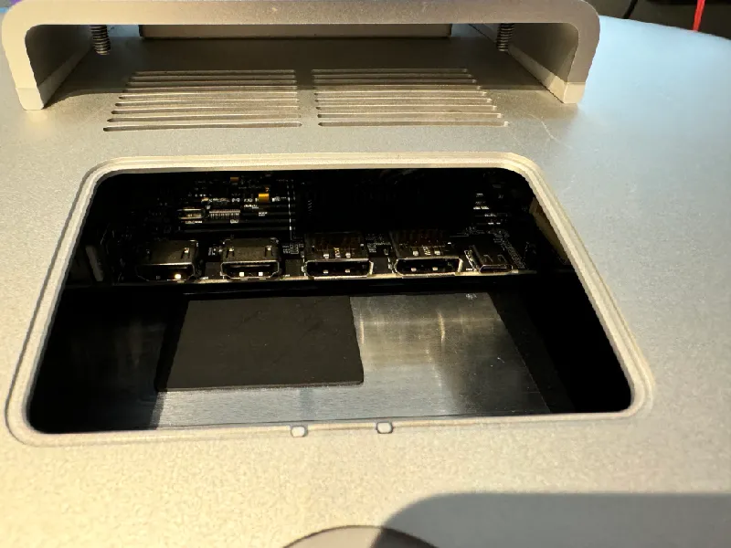
- Measure it meticulously to ensure the ports align to the opening in the iMac case (the opening used for accessing the memory of the iMac)
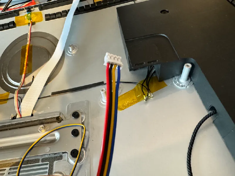
- Use the supplied cables to connect the LCD to the board (see images for the correct orientation of the plugs)
- Tape the cables down
Button panel option 1: In VESA mount
Only applicable when you have an iMac with VESA mount. This is an easy solution, but the buttons are a bit in an awkward place. Not a real big problem if you have the remote.
- Print R1811_imac_vesa_mount_button_panel.stl in PETG or ABS
- Use supports
- Print R1811_vesa_mount_button.stl five times in PETG or ABS, use supports!
- If you feel creative and have a multi-material printer: use a 0.2 nozzle and add symbols
- I have included a file for a BambuLab X1C printer with 0.2 nozzle: R1811 buttons with symbols for BambuLab X1C with 0.2 nozzle.3mf
- Use a Dremel tool to cut a hole in the to route the cables through
- As an extra option you can use the iMac's existing power button by extending the cables and soldering it to the K1 button on the button panel board
- There is a hole for the IR receiver to be accessible, but you can also opt for moving the IR receiver to the front
- Do the buttons in the button panel casing in this order:
| K1 | Power |
| K2 | Next |
| K3 | Previous |
| K4 | Menu/Select |
| K5 | Exit/Input Select |
- Screw the board to the button panel casing, I used some aesthetically pleasing screws I sourced from this iMac
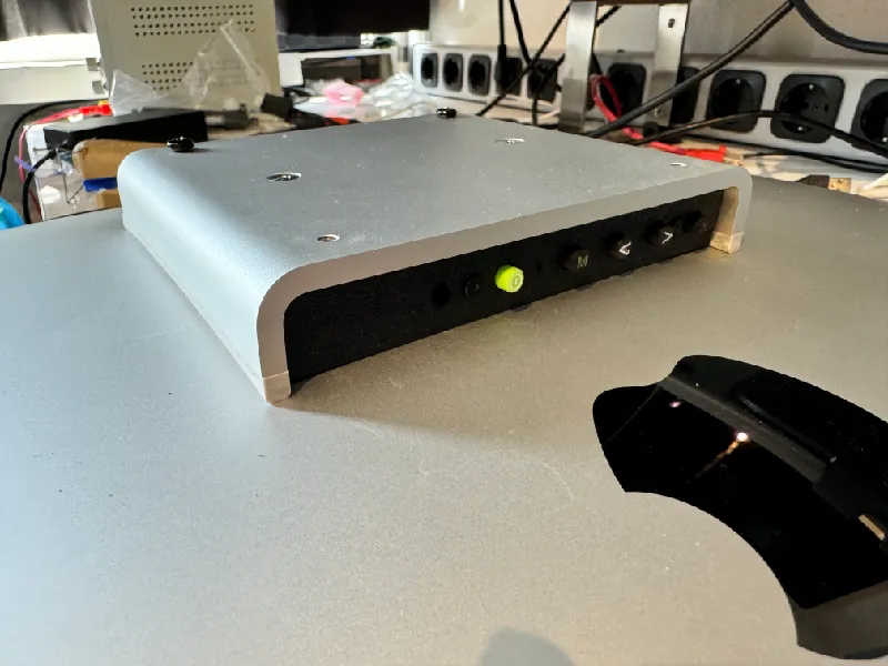
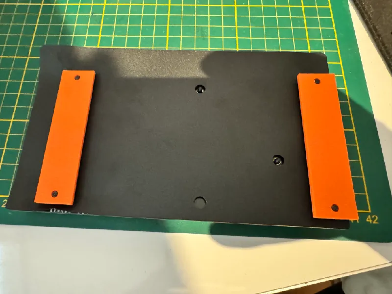
Button panel option 2: At the back side
This solution requires drilling in the case with a dremel tool and some more fiddling, but it's worth it as it as the buttons are in a very intuitive and handy position. And I did the heavy lifting for you with designing the 3D printed parts.
Requirements
- 2x DIN 7791 18mm M3 screws
- 2x M3 bolts
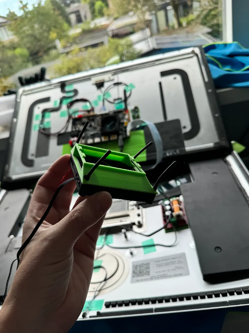
Overview of the assembly
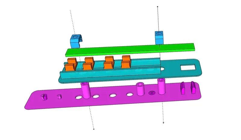
The purple part is the button panel on the outside of the case. The cyan parts is the mount on the inside. The orange parts are the buttons. The green part is the board and the blue parts are the holders for the m3 nuts.
Assembly instructions
- Cut a hole in the rear:
- Print R1811 rear button panel cutting template.stl
- Remove the jack plug from the inside with a flathead screwdriver. It is glued to the case
- Use the printed template to draw lines with a permanent marker
- The template has notches to correctly align
- Use dremel tool to cut the hole
- Print all the parts:
- R1811 rear button panel.stl
- R1811 rear button panel mount.stl
- R1811 rear button panel button.stl, no supports needed, print 4 or 5 times (see below)
- R1811 rear button panel nut holder.stl, print twice
- Decide if you need 4 or 5 buttons
- The fifth button is the power button
- If you use the power button of the case, you don't need to do anything here
- Otherwise you need to drill an extra 6mm hole in the marking on the backside of the rear button panel
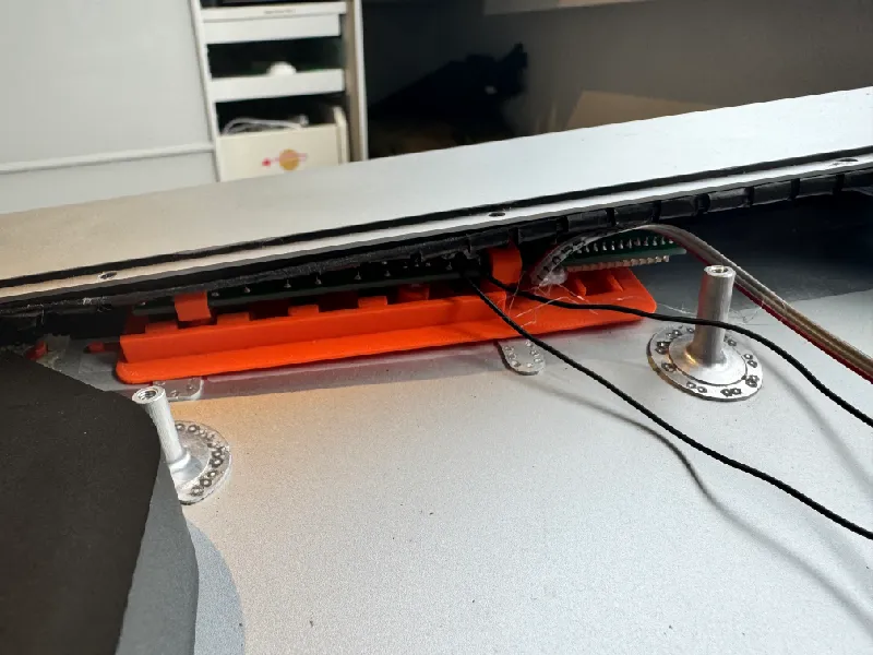
- Mount the front part first, use glue to fix it in place
- Then mount the rear mount from the inside
- IIt should slide over the 3 pillars. File the holes if needed
- If one of the screw pillars break, no worries, glue it back because the strength comes from the screws
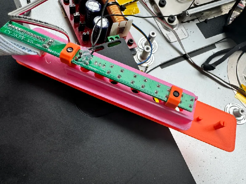
- Then the buttons
- I found it easier to first add the buttons in the rear mount, but you can also do it afterwards with tweezers
- See the previous section (option 1) on using the power button of the case on printing symbols on the buttons
- Do the nuts in the nut holders and clips those on the board
- This is a true life saver, I have tried it without these nut holders which sometimes also works
- You are welcome
- Then fiddle the board on top, align the holes and screw everything down

Remote holder in VESA mount
When you have a VESA mount and you have chosen for button panel option 2, then there's room for a remote holder.
- Print R1811 VESA mount remote holder.stl
- Push in the VESA mount. It's a very snug fit, but you are a grown (wo)man, you can do it.
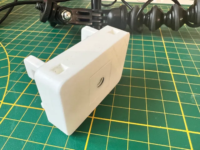
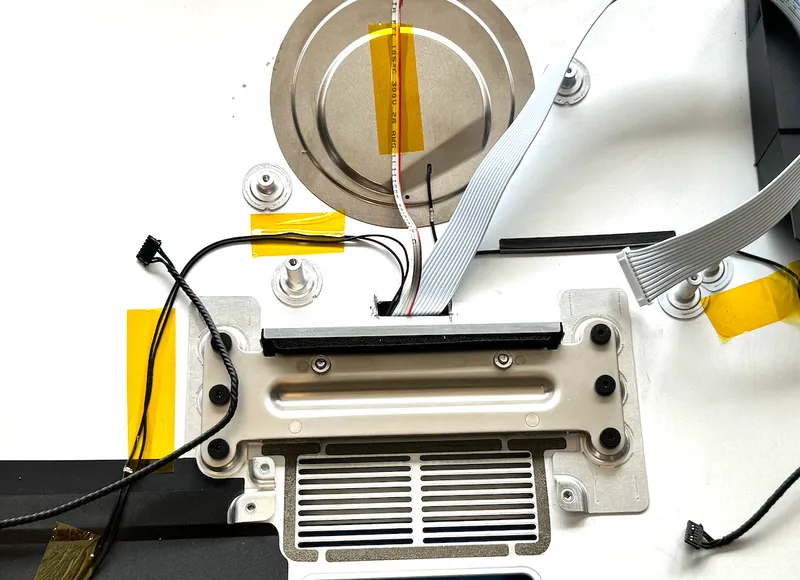
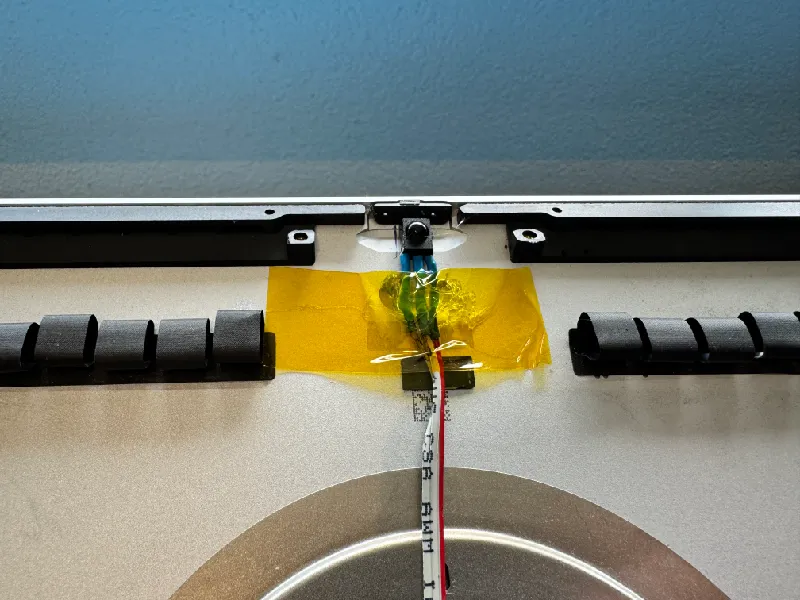
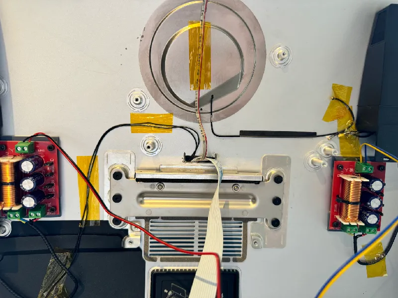
Moving the IR receiver to the webcam position
- Desolder the IR receiver component from the button panel board
- Extend the cable
- Glue/tape the IR receiver in place of the location where the webcam was
- Print R1811_ir_cover_for_button_panel.stl to cover the IR hole in the button panel casing
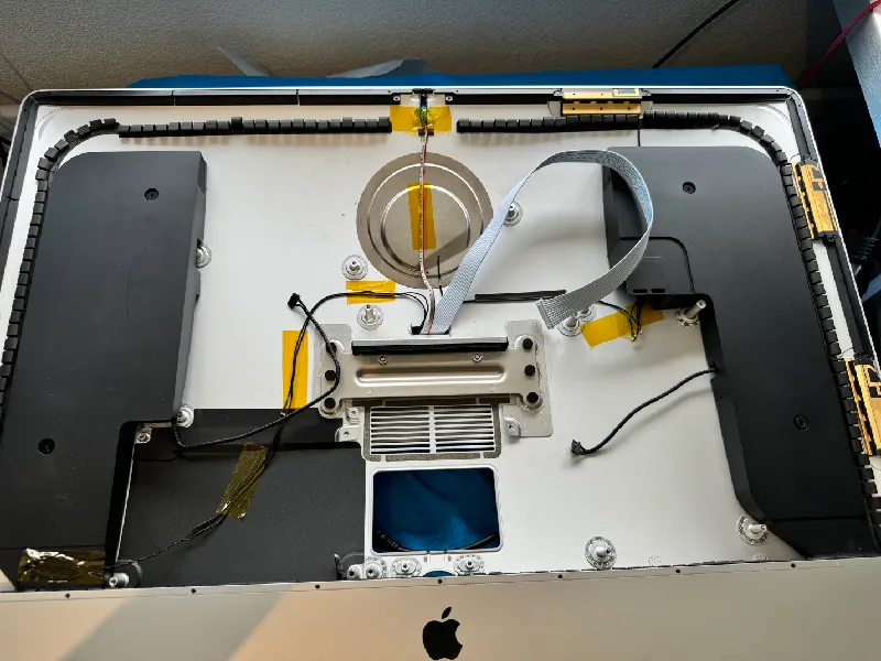
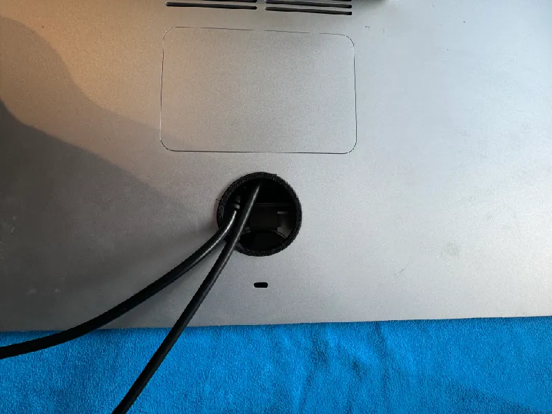
Connecting cables
You can open the memory cover with your finger by using the hole beneath it. Use the memory hole to connect all the HDMI/DP/USB-C/USB/power cables, but route the through the hole beneath it. Then close the cover.
- Print iMac_5k_hole_protection_tpu.stl in TPU to protect the cables
- Use supports for printing!
- Insert it in the hole
Connecting the speakers
- Both speaker casings contain two speakers. You need a crossover to connect them.
- Google, AliExpress, Ebay and Amazon are all your friends here: search for ‘imac 5K crossover’ to find a plug&play solution
- Alternatively you can find a more generic YLY-2088 board. It's cheaper but it doesn't have the correct connectors. To connect this:
- You need to find out the correct order of the cables (Apple most of the times only uses black cables for everything)
- Strip the cables and connect them to the board
- Leave all jumpers connected (JP A to JP D) as I found this to be the best sound quality
- With jumper B connected the impedance load on the amplifier chip (CSC3110) will be lower than specced, but I have tested and the chip doesn't get hot. See https://forums.macrumors.com/threads/diy-5k-monitor-success.2253100/post-33307182 for more info.
- Cheap ass as I am, I used the generic YLY-2088
- Print the yly-2088 crossover board mount.stl four times in PETG or ABS
- Put M3 inserts in the holes using a soldering gun
- Use double adhesive tape to mount the board to the iMac case
- Mount the boards using M3 screws
- The pinout for the speaker connectors in my iMac (where pin 1 is the one marked with an arrow on the connector) is as follows:
| Pin | Color of the heatshrink marking in the pictures | |
| 1 | Woofer + | Red |
| 2 | Woofer - | Black (no heatshrink) |
| 3 | NC | |
| 4 | NC | |
| 5 | Tweeter + | Yellow |
| 6 | Tweeter - | Blue |
- These are connected to the woofer and tweeter inputs on the YLY-2088 as can be seen in the pictures
- The connector on the R1811 board is a PH 2.0, the pinout is as follows (note the markings on the board are wrong!):
| Pin | Color of the cable in the pictures | |
| 1 | Left + | Red |
| 2 | Left - | Black |
| 3 | Right - | Yellow |
| 4 | Right + | Blue |
- The sound of the speakers is amazing, much better than I anticipated
Optional: bigger, quieter fan
Requirements:
- 12V 80x80x10mm 4 pin fan (I bought an NO-8010-PWM fan on AliExpress)
- 4 pin PWM temperature controller (I bought this one on AliExpress)
- Silicon fan mounts (for example these ones)
Then:
- Drag R1811 80mm fan adapter rev 7 top.stl, R1811 80mm fan adapter rev 7 middle.stl and R1811 80mm fan adapter rev 7 bottom.stl into your slicer and choose import as single object (or something like that, this works in OrcaSlicer)
- Reason: there is an error in R1811 80mm fan adapter rev 7.stl, the above works
- Print with supports in ABS or PETG
- Optionally print R1811 80mm fan adapter gasket.stl in TPU for further vibration reduction
- Remove the old fan from the heatsink (3 screws)
- Tape the temperature sensor in the heatsink
- Mount the fan on the fan adapter using the silicon fan mounts with (optionally) the gasket in between
- Slide the fan adapter from one side over the heatsink, then the other side
- Note the the longer side (the overhang) is pointing towards then connectors-end of the board
- Check that the heatsink is not be tilted
- I configured the PWM controller so default rpm is the lowest and the low threshold temperature is 35 degrees celsius and the ‘width’ is 15 degrees (so the high threshold is 50 degrees).
- Most of the times the fan will be off (logic on the R1811 board), and when it turns on it will turn inaudibly. It increases linearly when the temperature rises.
References
This forum deserves all credits: https://forums.macrumors.com/threads/diy-5k-monitor-success.2253100/
Go there if you have another iMac model or board to find useful information
Model origin
The author marked this model as their own original creation.