Clock Gear Train Assembly

Description
PDFBackground
The primary aim of the project is to provide a clear technical illustration of the inner workings of a 3D printable pendulum clock. In my research on the topic it was incredibly challenging to find clear illustrations of key concepts and how and why those decisions were made. The aim is to clearly illustrate and explain, therefore please comment and ask if anything is not clear.
Drivetrain Description
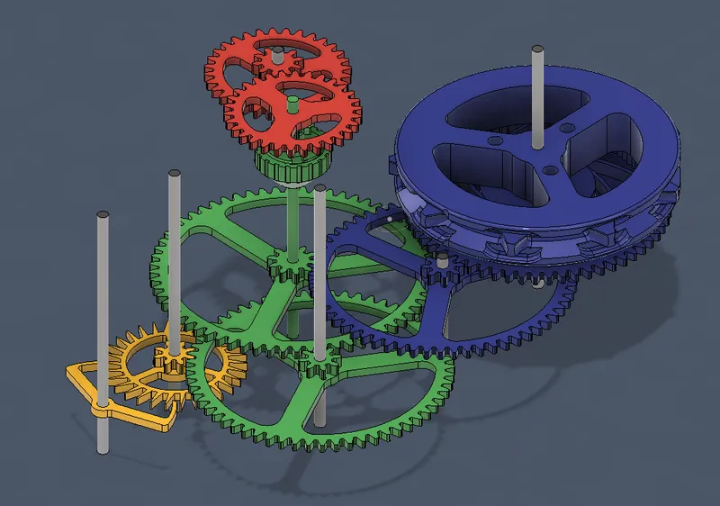
The drivetrain layout, currently V11 in this project evolved over 3 major design iterations. In the selection process of gear ratios you have to consider the ratio but also the physical dimensions of the gear that results from the ratio with pivot points that do not intersect with the gears or teeth.
The easiest approach is to simply align in a straight line, but turning the gears away at angles shortens the total length and creates a smaller compact design.
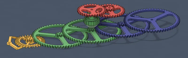
The final rotation position was chosen to aligns the escapement in yellow with the shaft holding the hour and minute hands. Then the blue parts arranged so the weight will be hanging in line with the centreline of the assembly to keep the system in balance.
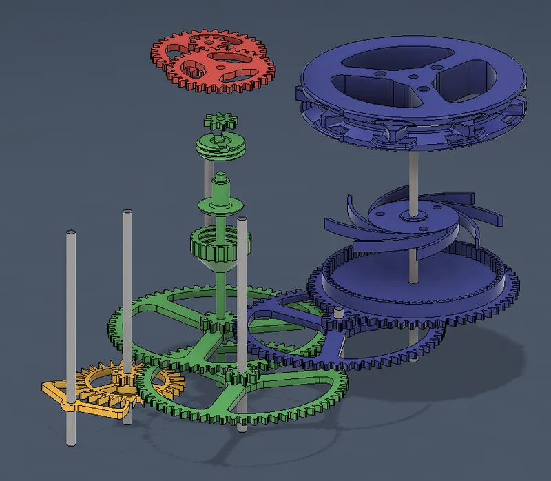
The exploded view then helps to show the assembly and facilitates functional description.
The Escapement Assembly
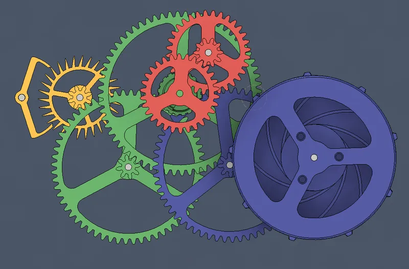
The escapement assembly is shown in yellow and is designed around a 98cm pendulum. 98cm corelated with the gravity constant and creates a 2 second tick-tock heart beat, and with 30 teeth in the escapement gear results in the yellow gear completing one full rotation is 60 seconds.
The Minute Gears
The two big green gears have 60 and 64 teeth respectively. On top of those two gears are two small gears called pinion gears and they have 8 and 10 teeth respectively. The gear ratios however are determined by the yellow pinion gear and the first green pinion gear of which both have 8 teeth. So 60/8 gives a first gear ratio of 7.5 and 64/8 a second ration of 8.0. Combined then you have a ratio of 7.8x8.0=60 that gives the green shaft a full rotation every 60 minutes.
The Friction Clutch
In the middle of the green gear shaft between the bottom pinion gear and the top pinion gear is the friction clutch.
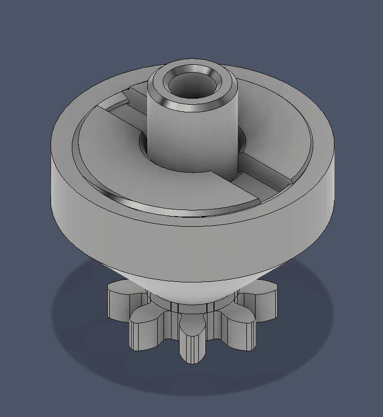
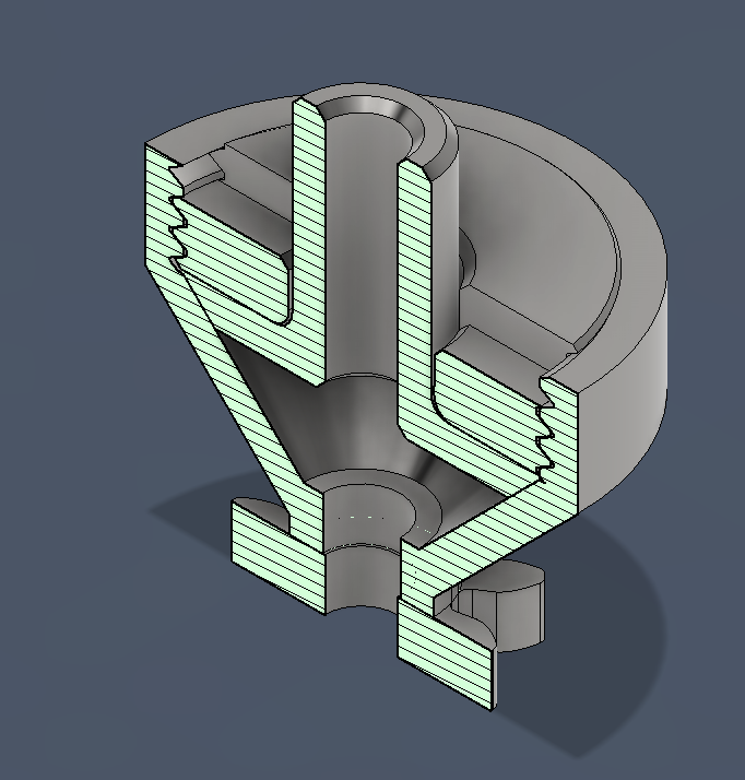
The friction clutch disconnect the minutes gear shaft from the rest of the assembly with a clutch mechanism that is friction adjustable. Under normal operation it drives the shaft normally, but allows the hour and minute hands to be adjusted to reflect the current time. This adjustment is possible by moving the minute hand directly on the face of the clock.
The Hour Gears
The hour gears in red, are finally driven by the top green pinion gear with 8 teeth driving a 32 tooth gear with a ratio of 4.0. On top of the red 32 tooth gear is a 10 tooth pinion gear driving a 30 tooth gear resulting is a ration of 3.0, Combined then we have a ratio of 4x3=12. The final red gear make one complete revolution every 12 hours, directly driving the hour hand.
That is the timekeeping part of the clock sorted.
The Click Power Source
The blue gears creates the clock power source. The size of the gears are mostly determined by the physical sizes of the other gears and then secondly to get a chain drive that is slow enough the take 10 days to work through 1.5m of chain so the clock can keep running for 10 days without human intervention.
The chain spool pitch diameter is 93.25, so will go through 156cm of chain in 162,000 seconds
| Teeth | Pinion | Ratio | Comb | seconds | min | hours | revs/24h | 93.25 |
| 30 | 8 | - | 60 | 1 | ||||
| 60 | 8 | 7.5 | 450 | 7.5 | ||||
| 64 | 8 | 8 | 60 | 3600 | 60 | 1 | 24 | 7031 |
| 60 | 10 | 7.5 | 27000 | 450 | 7.5 | 3.2 | 937 | |
| 60 | 6 | 45 | 162000 | 2700 | 45 | 0.53333 | 156 |
That means the chain spool will complete about a half a revolution per day and take ten days to move the weight to the ground with 1.5m of chain.
| hours | revs/24h | 93.25 |
| 1 | 24 | 0.2 |
| 7.5 | 3.2 | 2 |
| 45 | 0.53333 | 10 |
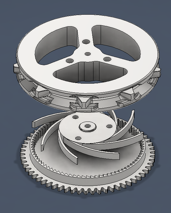
The chain spool has a ratchet mechanism that allows the other end of the chain to be pulled and get the chain weight back to the top again without having to stop the clock and rewind the chain.
That's it, the full clock drive train. The fusion 360 model is included with the project files.
What's next
- Design an adjustable pendulum assembly
- Design a 3D printable chassis to hold the full assembly
How to print the parts
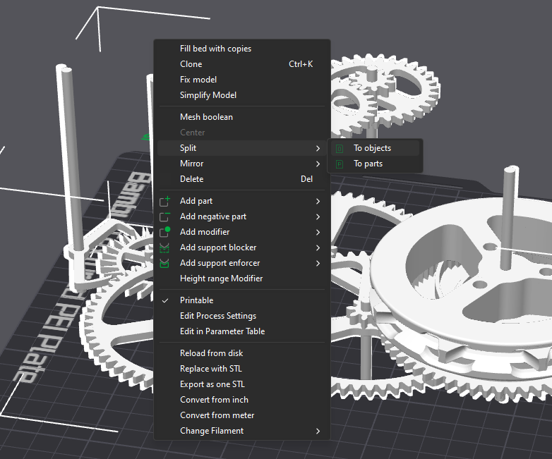
Import the stl file into your slicer and select “Split → To objects”
Tags
Model origin
The author marked this model as their own original creation.