Afterburner & Variable Nozzle


Description
PDFIntroduction
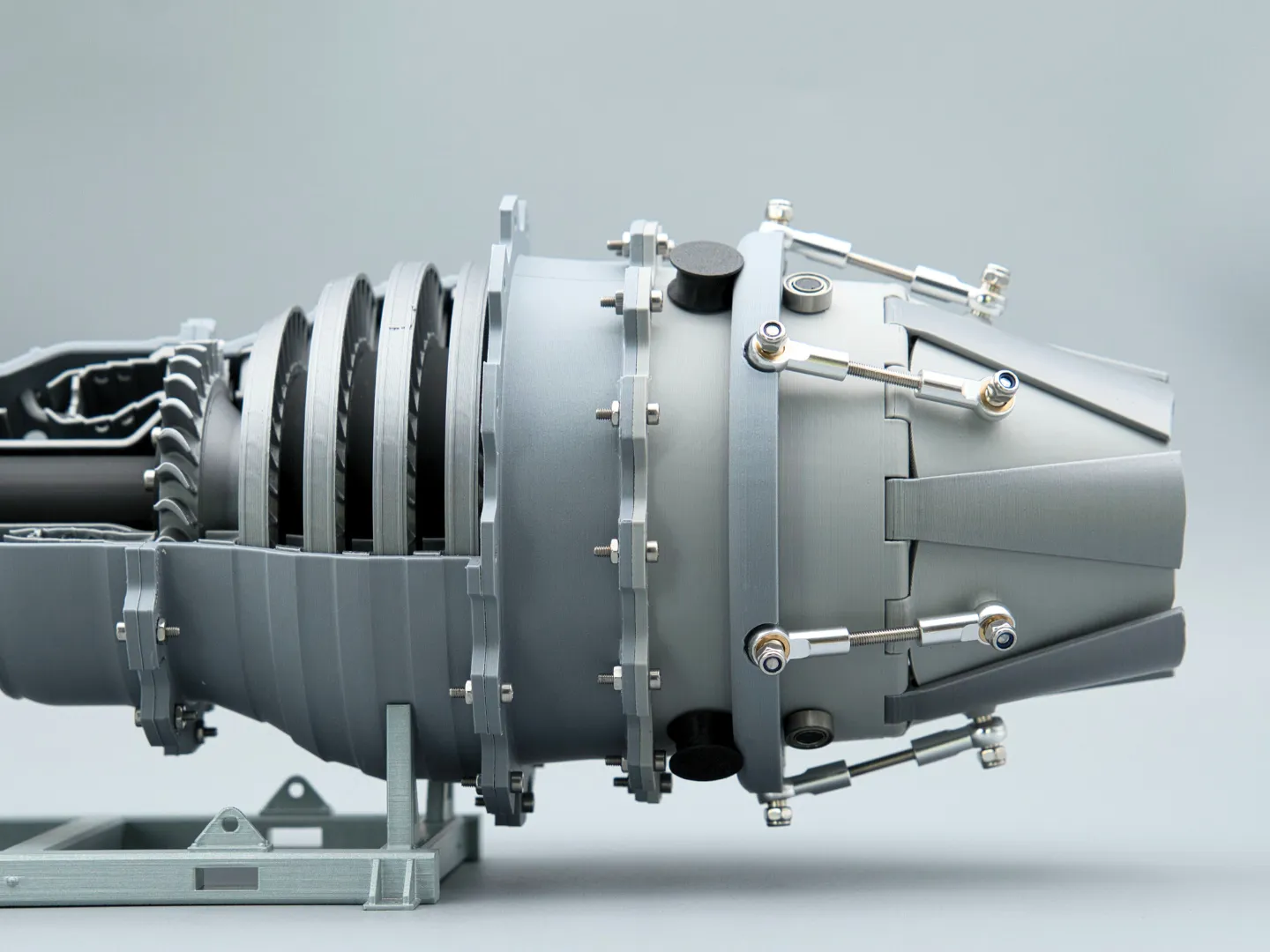
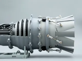
The 3D Printable Jet Engine is great! However, I wanted a turbojet or low bypass turbofan to complement the original. So, I got to work designing the turbojet, afterburner and variable exhaust nozzle.
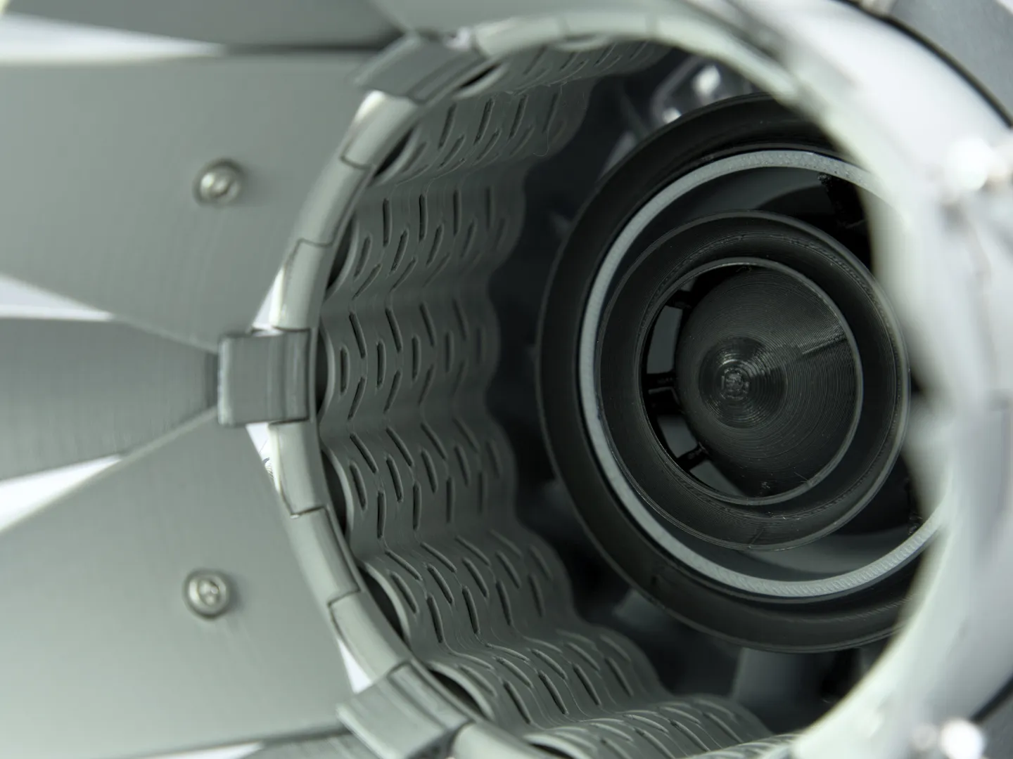
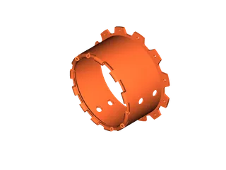
For this build you'll need additional hardware. It adds afterburner and nozzle, making the model longer. The design philosophy matches the turbofan, with hints of the GE J79 visible in the liner and flame holders.
I designed a stand. Making the jet sit low to the ground. It works great!
I made a video and written instructions for assembly. ( Video is more thorough).
My print profile (Bambu Studio) uses three colors and 0.16mm layers for smoother hinges.
I offer a great kit on my website. It provides quality hardware and greatly supports my work. Thank you.
Check out the Turbojet engine!
Happy printing and great success! Message me with any questions!
(The tolerances are optimized for BambuLab Printers.)
Required Components
- M3 Nyloc Nut 12x
- M3 12mm Bolt12x
- M3 25-30mm threaded Rod 6x
- MR105 bearing 6x
- M3 Tie Rod End 12x
- 270mm 1.75mm Filament 1x
Tools used for assembly:
- M2 & M2.5 Screwdriver
- Pliers or anything that can hold nuts
- Plastic Glue
Assembly
| Only glue on the bottom three pins for now. Use plastic glue. |  |
| This is a press fit. Don't use glue. |  |
| Again a press fit. Don't use glue. |  |
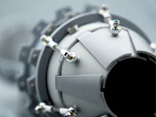
| Screw the tie rods onto both sides of the threaded rods. |  |
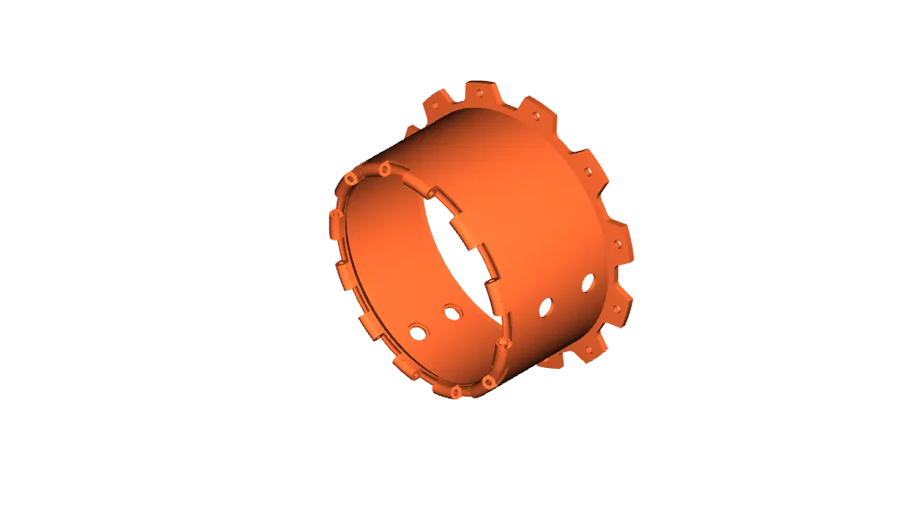
| Use six Nyloc Nuts to fixate the rods onto the control ring. Make it tight. Make sure you don't deform the plastic too much. |  |
Use the 270mm filament as a hinge for the primary and secondary petals.
On the main body, feed the filament through the hinge with the larger hole.
Start by adding a primary petal. Then alternate ending with the secondary petal with the knob on it.
Push the filament all the way into the larger hole using your screwdriver. Now attach the secondary petal. Make sure everything moves freely.
For visual explanation go watch my video. | 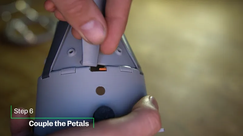 |
| Easy… | 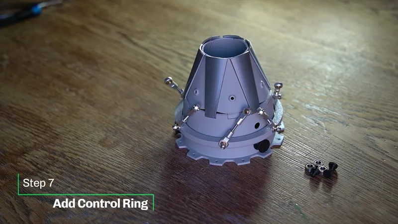 |
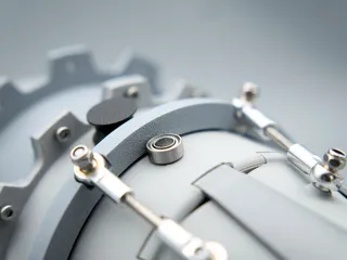
Now add the second pair of bearing pins. ( I don't glue them on in case I want to remove the ring.
Attach the remaining three bearings to them.
The control ring shouldn't have to much freedom up and downwards. |  |
Insert a bolt into every primary petal.
Adjust the length of the tie rods. In a vertical position the petals should be in the closed condition.
Don't rush this step. Take your time. It will be great! | 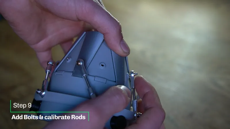 |
| Secure the rods with six Nyloc nuts. | 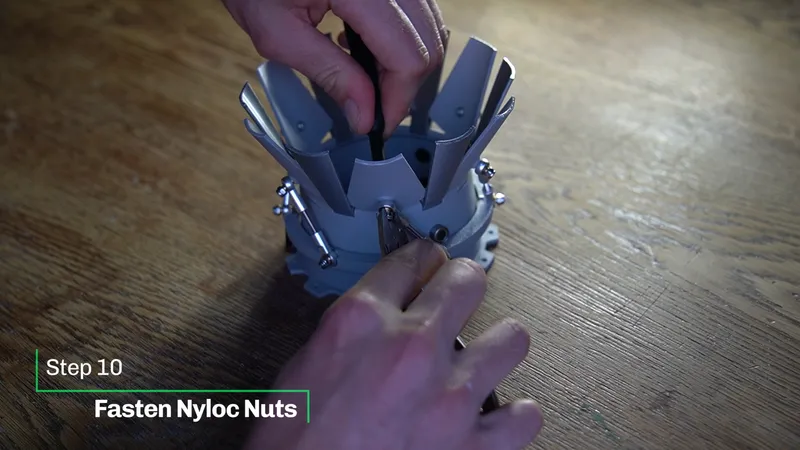 |
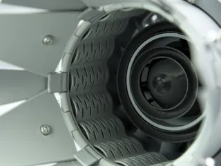
Align the corrugated liner using the three slots.
Bolt the Assembly onto the jet engine. (I had difficulties attaching one screw.) |  |
| Last step… Make sure everything works. Congratulations! Thanks for printing! |  |
| Placement of the engine on the stand |  |
Designed by linus3d
My website: https://linus3d.de/
Tags
Model origin
The author marked this model as their own original creation.


