Meshtastic Gendemik CHUNKY "MAXIMUS" HeltecV3 Remix


Description
PDFHow to and schematics in progress!
WARNING! This is a pretty advanced build! You have to know your way around with soldering lots of tiny and fragile wires, electronics etc. There is no programming involved but you need a steady hand and some knowledge when it comes to connecting electronic modules and Lithium Ion batteries together!
________________________________________________________________________________________________
I got special permission from Gendemik to share my remix! I had to choose “Original, I made it” to publish the remix as I am not able to link to the original design as its license does not allow sharing and remixing.
AGAIN the BASE DESIGN IS NOT MY CREATION! I just got permission from Gendemik specifically for my REMIX that allows me to share it!!
Dont miss out to check their other creations and leave them a like for allowing me to share my remix with the world!: Gendemik | Printables.com
You can find the original design this remix is based of here: GDMK Heltec v2/v3 Chunk 18650 (modular case project) Meshtastic inspired by Gendemik | Download free STL model | Printables.com
_____________________________________________________________________________________________________
:
You probably started off with Muzis H1 or Tony Gs Heltec cases, which are totally awesome but they do lack in the runtime compartment.
With muzis H1, 1 day max at best, with tony G maybe 2 but probably less. This is fine in the beginning because the designs are awesome and your just happy it works and looks nice, but it starts to show its weakness when you really wanna “use” it, constantly having an eye on the battery charge kind of sucks not knowing if you will make it over the day in addition the heltec board charge super slow…..well its really not great.
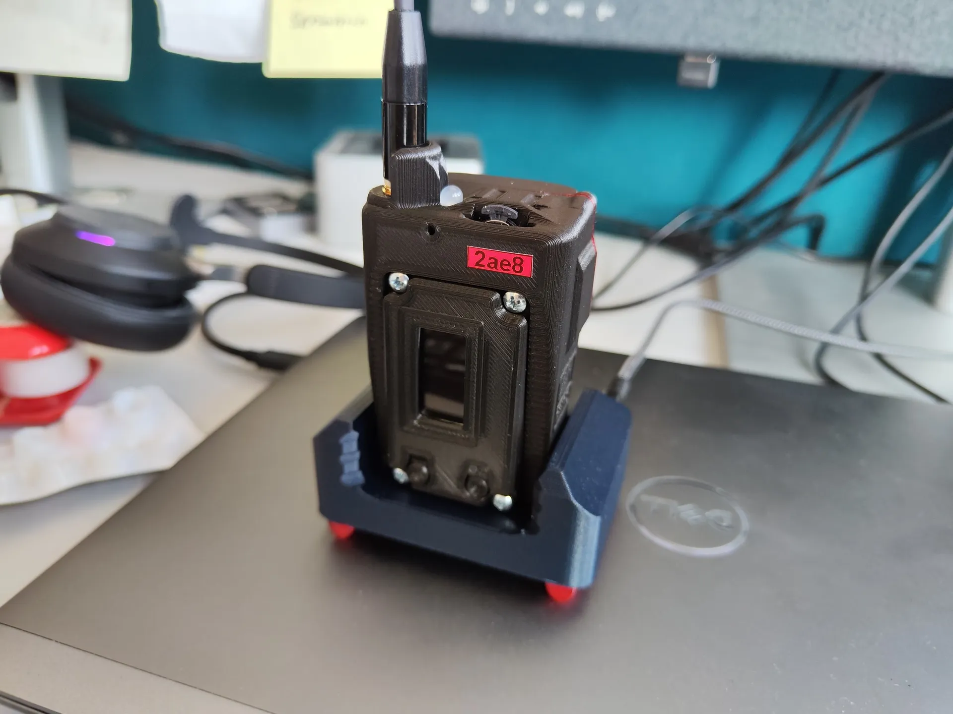
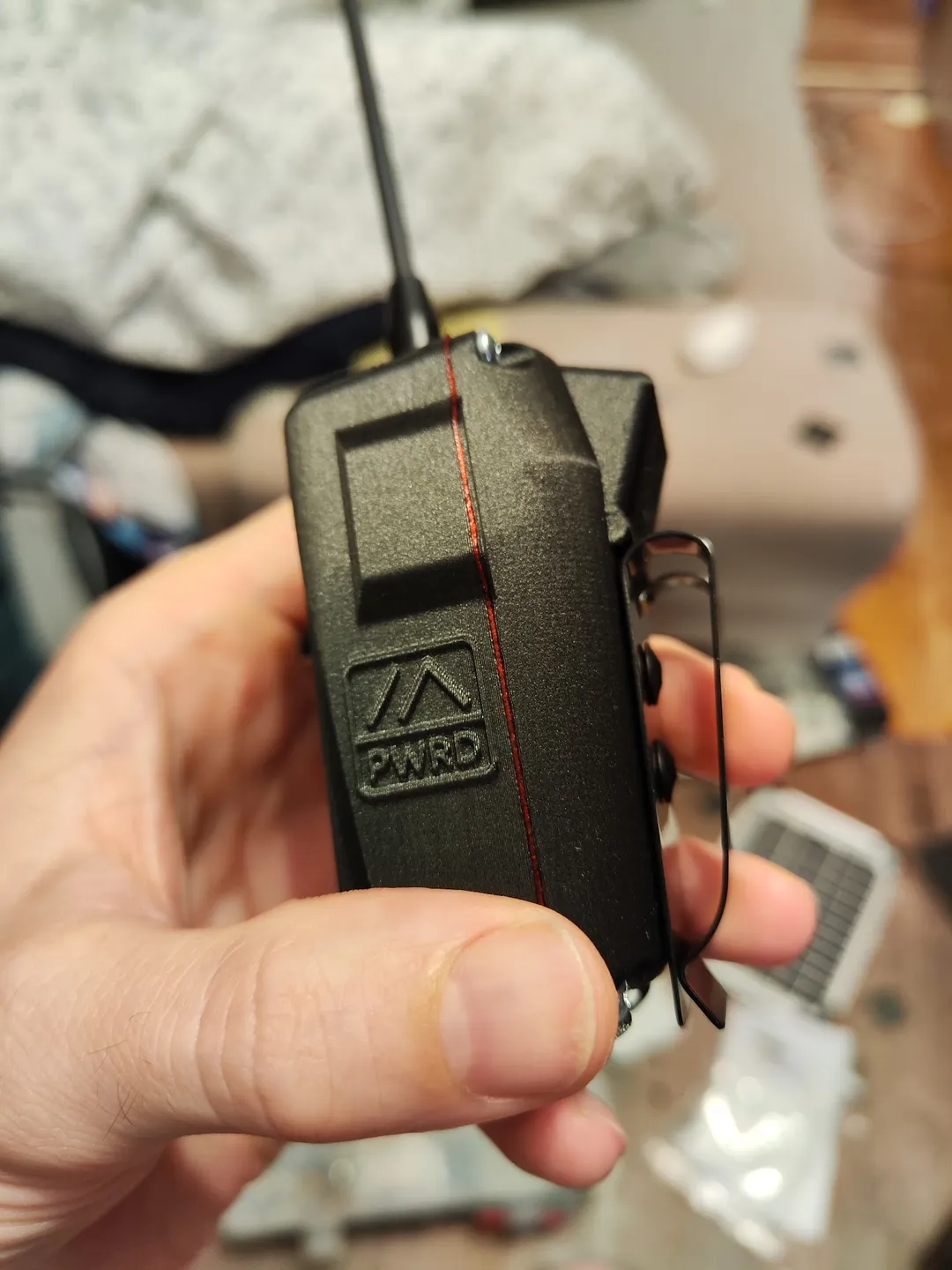
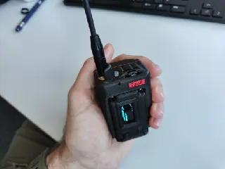
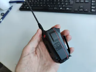
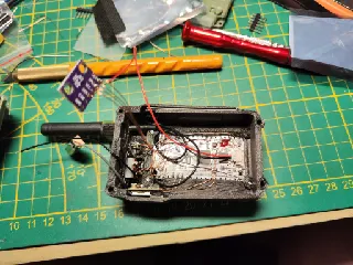
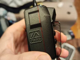
The CHUNKY Maximus is the swiss knife of Heltec V3 Meshtastic devices.
It packs more features and runtime then any other heltec V3 meshtastic device available for its size as of now!
CHECK OUT ALL THE CHANGES and UPGRADES DONE TO IT BELOW AND YOU WILL APROVE THE PROUD NAME “MAXIMUS” :D
:
_______________________________________________________________________________________________________
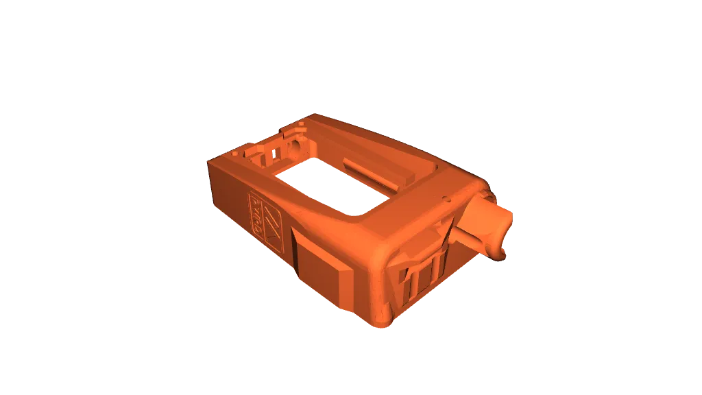
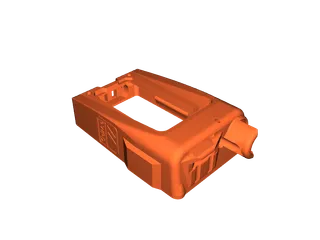
Print orientation and support material:
Print the three main case parts in the orientation shown in the preview and use supports up from the print bed. Structures that need additional support like the cutout for the magnetic pogo pin connector has supports already in place, other cutouts should be fine with just small bridging.
If your printer bad with bridging you can go with " supports everywhere but its a pain to remove it especially on the upper side of the middle frame.
____________________________________________________________________________________________________
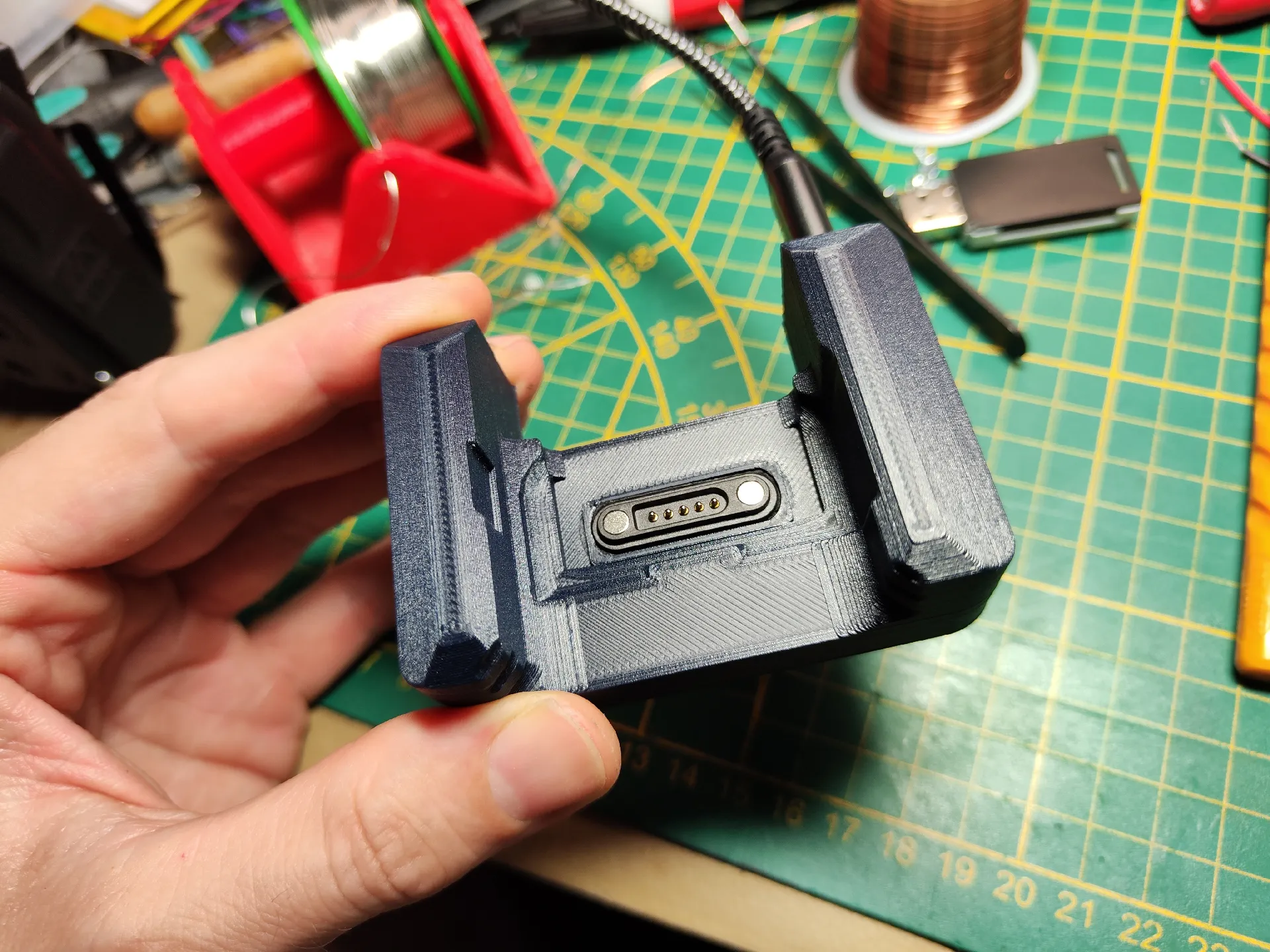
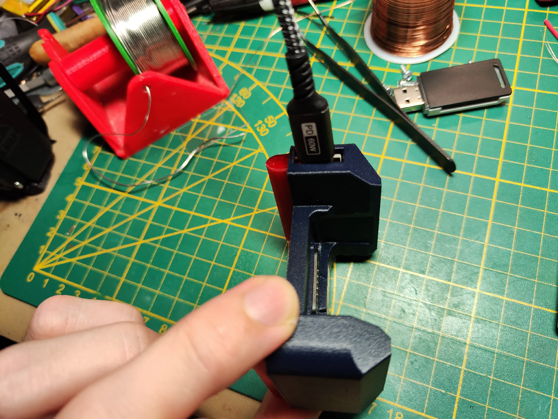
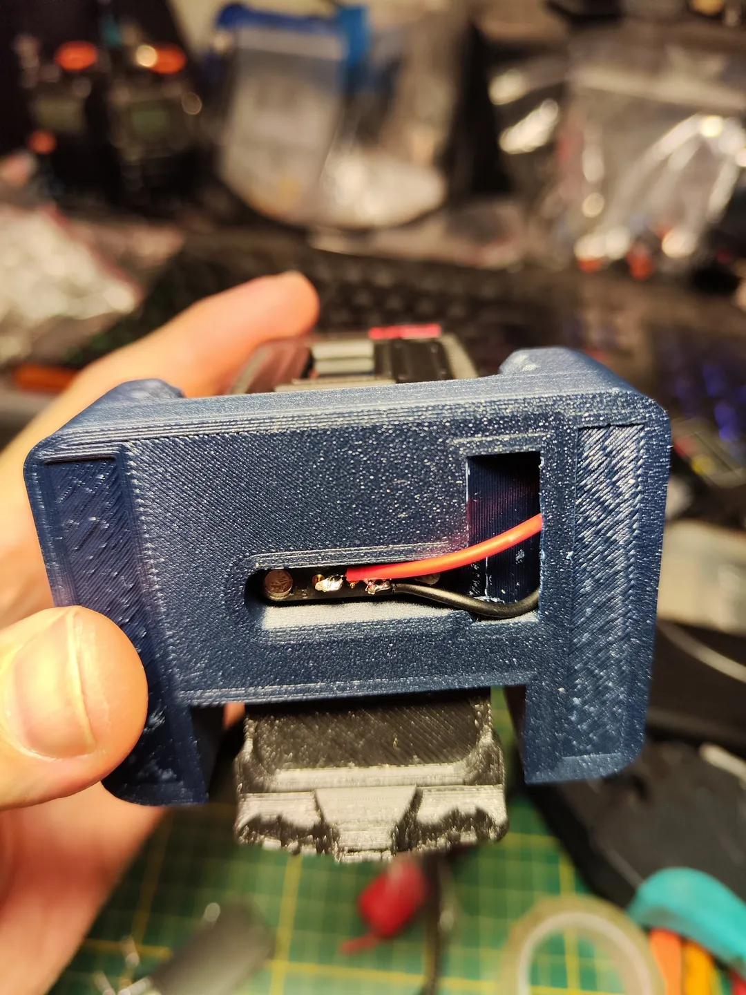
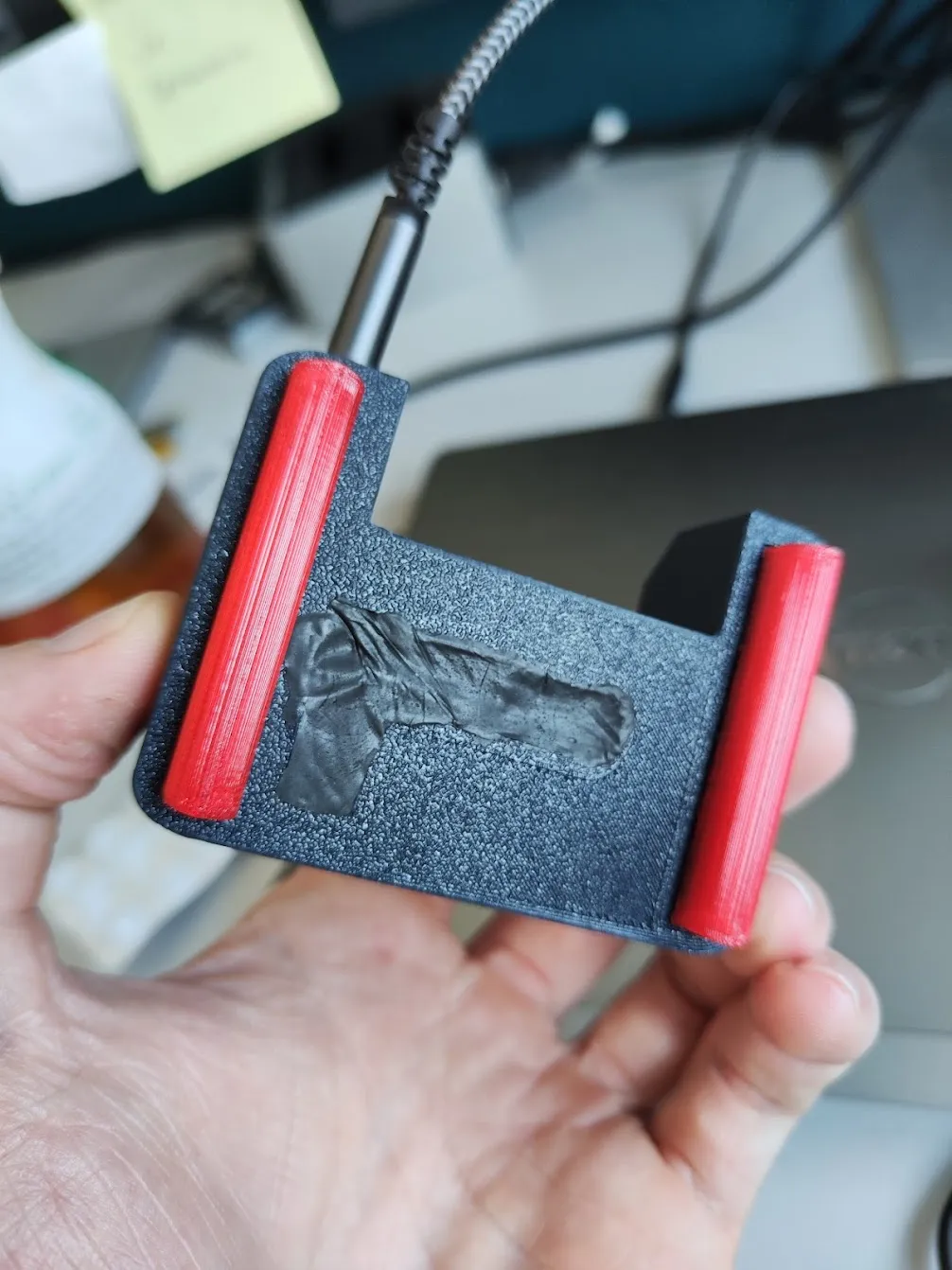
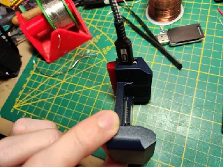
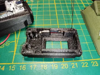
Charging cradle:
The easiest build of the project.
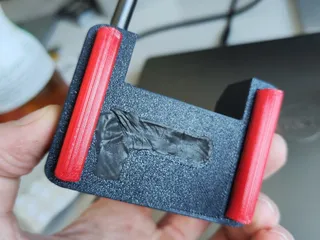
Print the feet in TPU and the main part in PLA /petg.
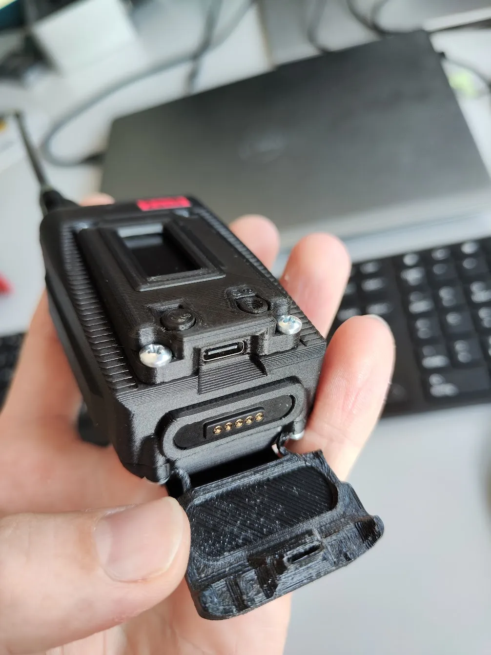
for a perfect connection between the connector on the charging cradle and the lower side of the maximus I simple used some 2 component epoxy kit you can form with your hands easily like play dough. Lower the finished maximus in the cradle with the counterpart coming from the other side before they meet and attach to each other.
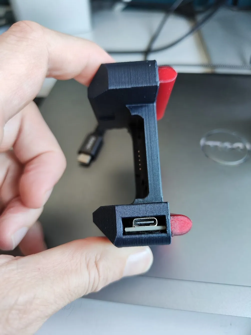
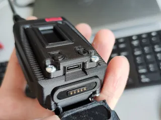
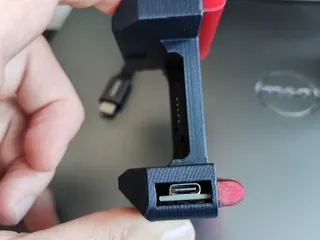
I used double sided tape to glue the USB C charging board to the inside of the slot you slide it in, the USB C connector of course facing outwards so you are able to attach a usb C cable to it.
use epoxy to fill up the whole back cavity ( check pictures) and make sure that both halves of the magnetic pogo pin connectors are still locked while doing so.
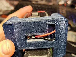
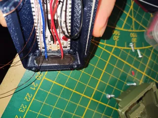
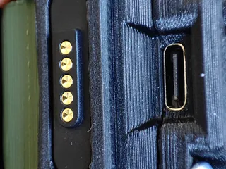
Of course before filling up everything with epoxy you need to connect the USB C charging board with the magnetic pogo pin connector. Choosing a 5 pin connect the + and - cable from the charging board needs to be soldered to 2 connectors each, leaving the middle one unused.
No worries here each pole from the charging board utilizing two contact points is enough for 15 watts as I did this in many many other builds the same way and never encountered a problem with heat!
I left the maximus in the cradle over night to let the epoxy harden completely, that way I was absolutely sure the distance between the two connectors is perfect! ( check pictures)
__________________________________________________________________________________________________________
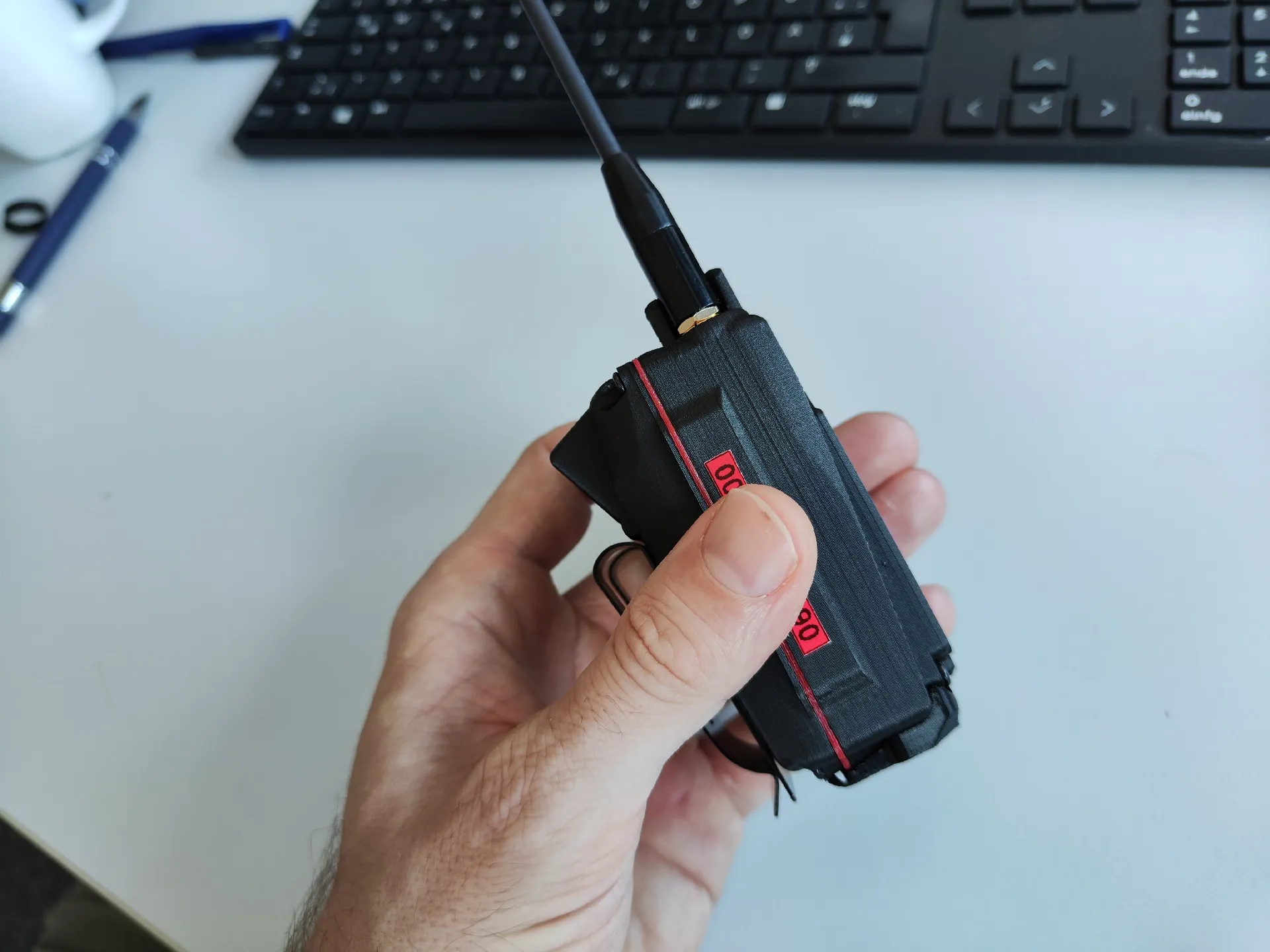
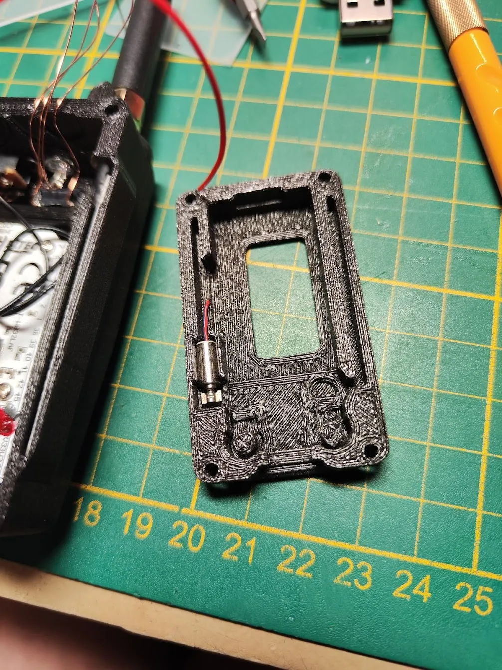
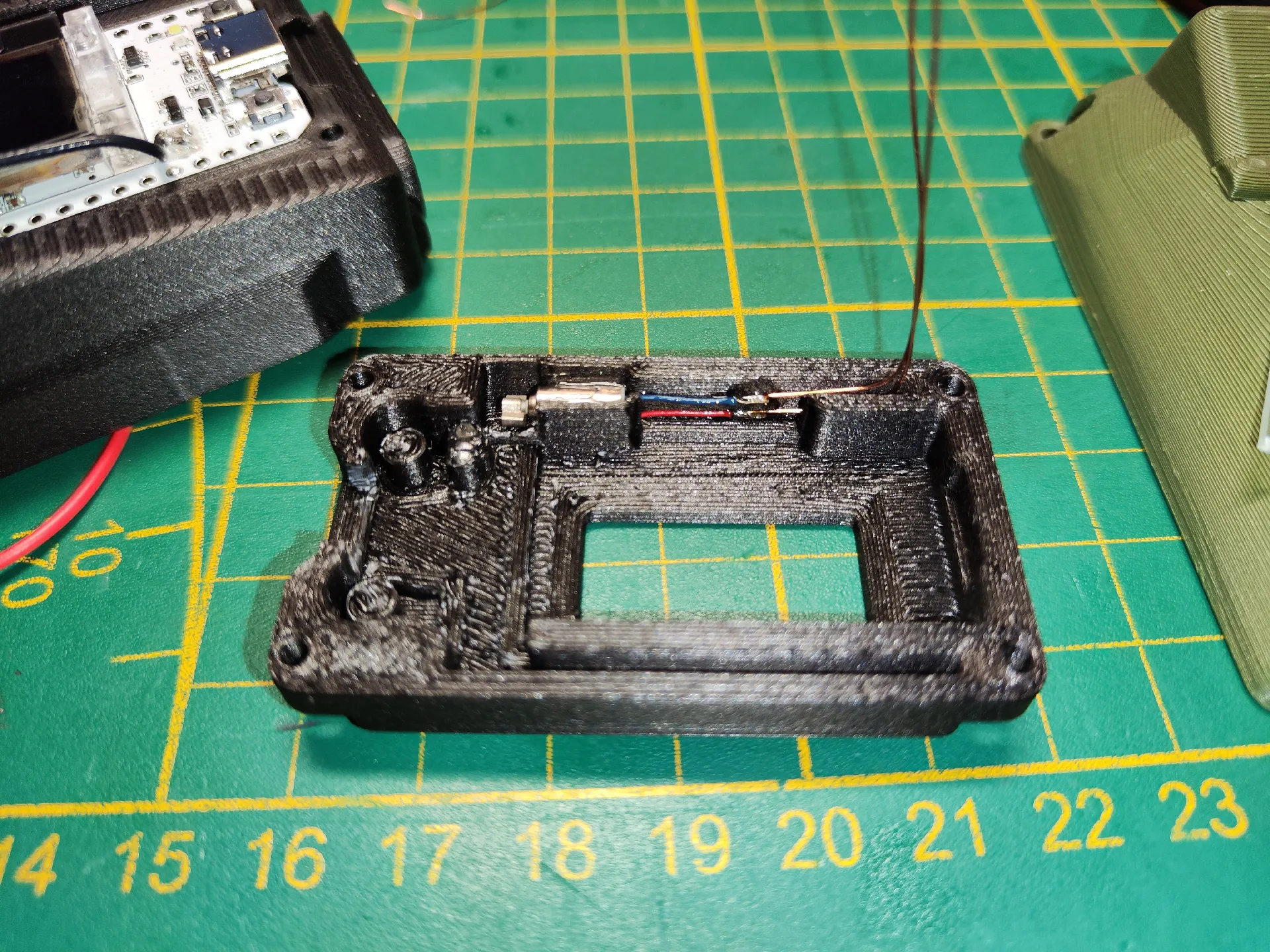
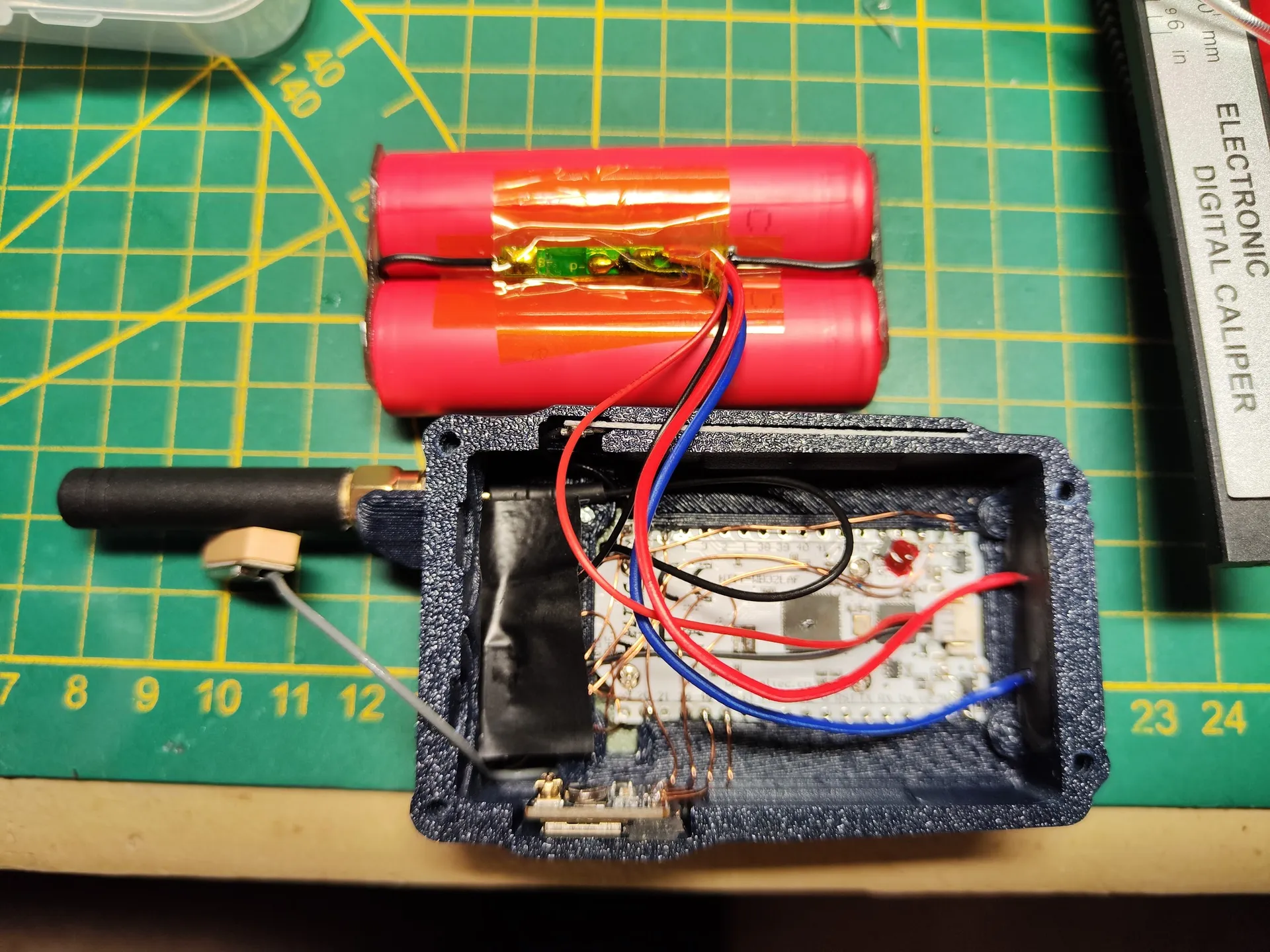
External Wifi/ bluetooth antenna:
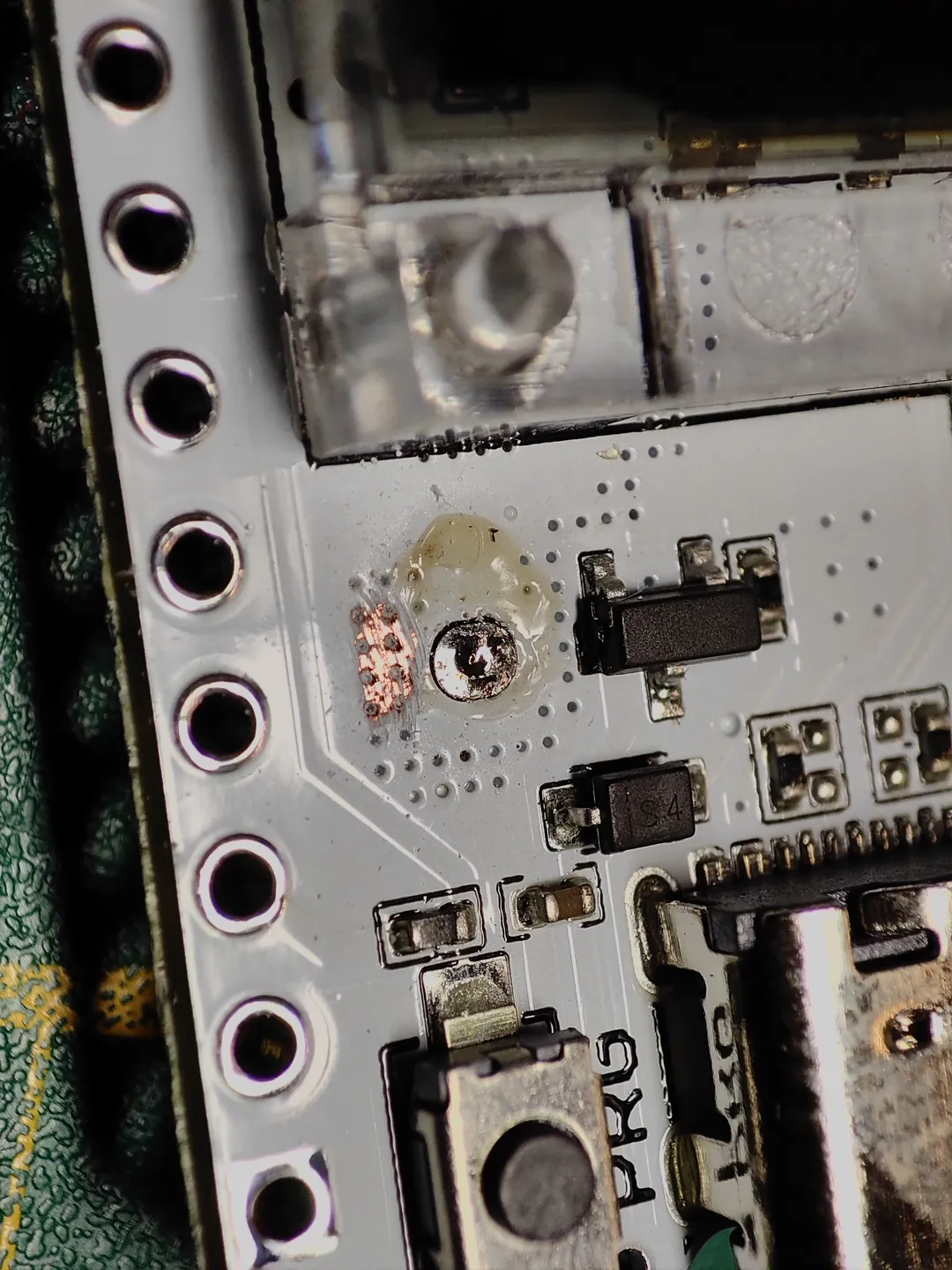
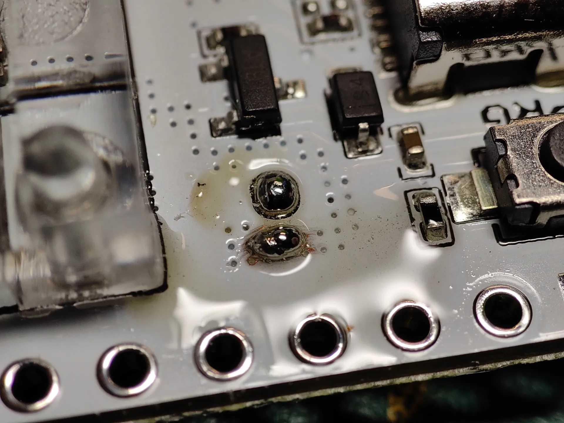
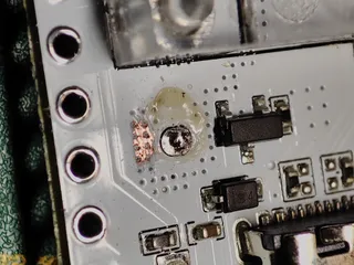
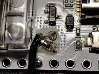
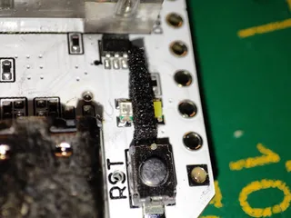
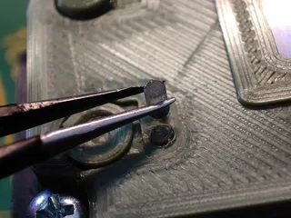
Unsolder the original coil antenna.
Use a scalpel to scratch the white paint away right next to the desoldered antenna connection point ( check pictures) carefully until you see shiny copper ( dont scratch to hard or you scratch away the copper layer!)
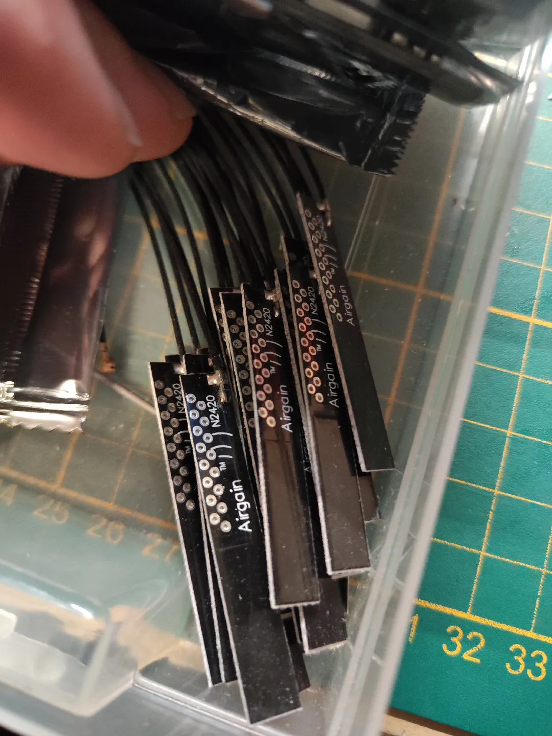
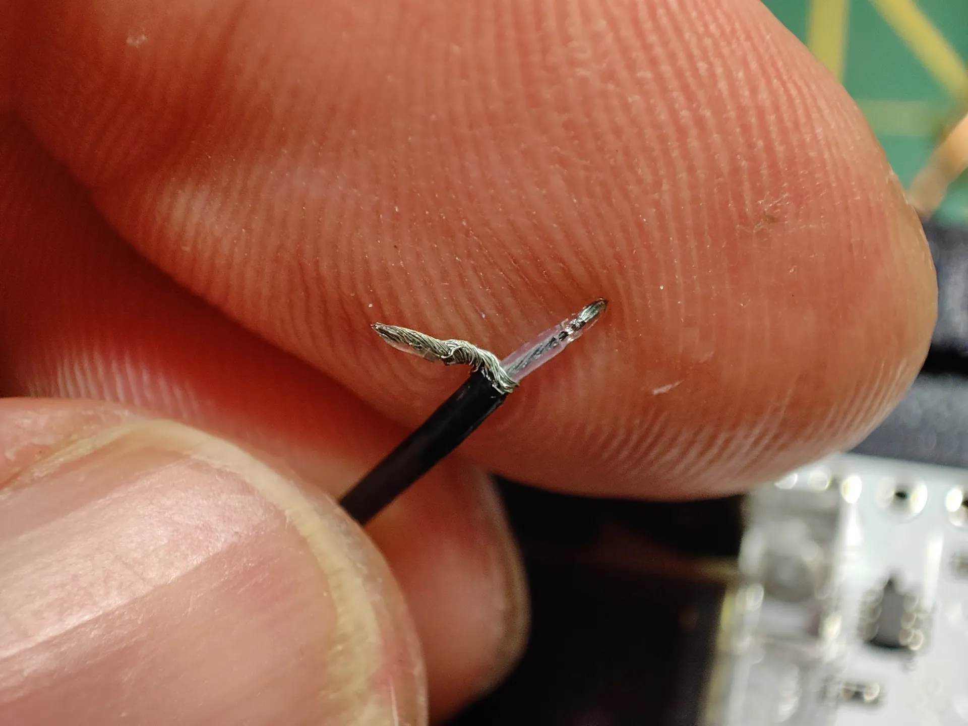
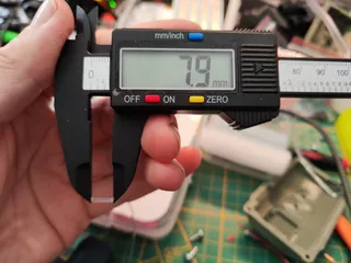
Take the PCB Airgain antenna and cut off the Ipex connector at the end. carefully strip the cable 2.5mm and get rid of the black outer mantle, then twist the cable shield together and bend it to the side, strip the middle cable exposing the actual antenna signal cable. solder the signal cable to the coil antenna spot and the shielding to the scratched open ground.
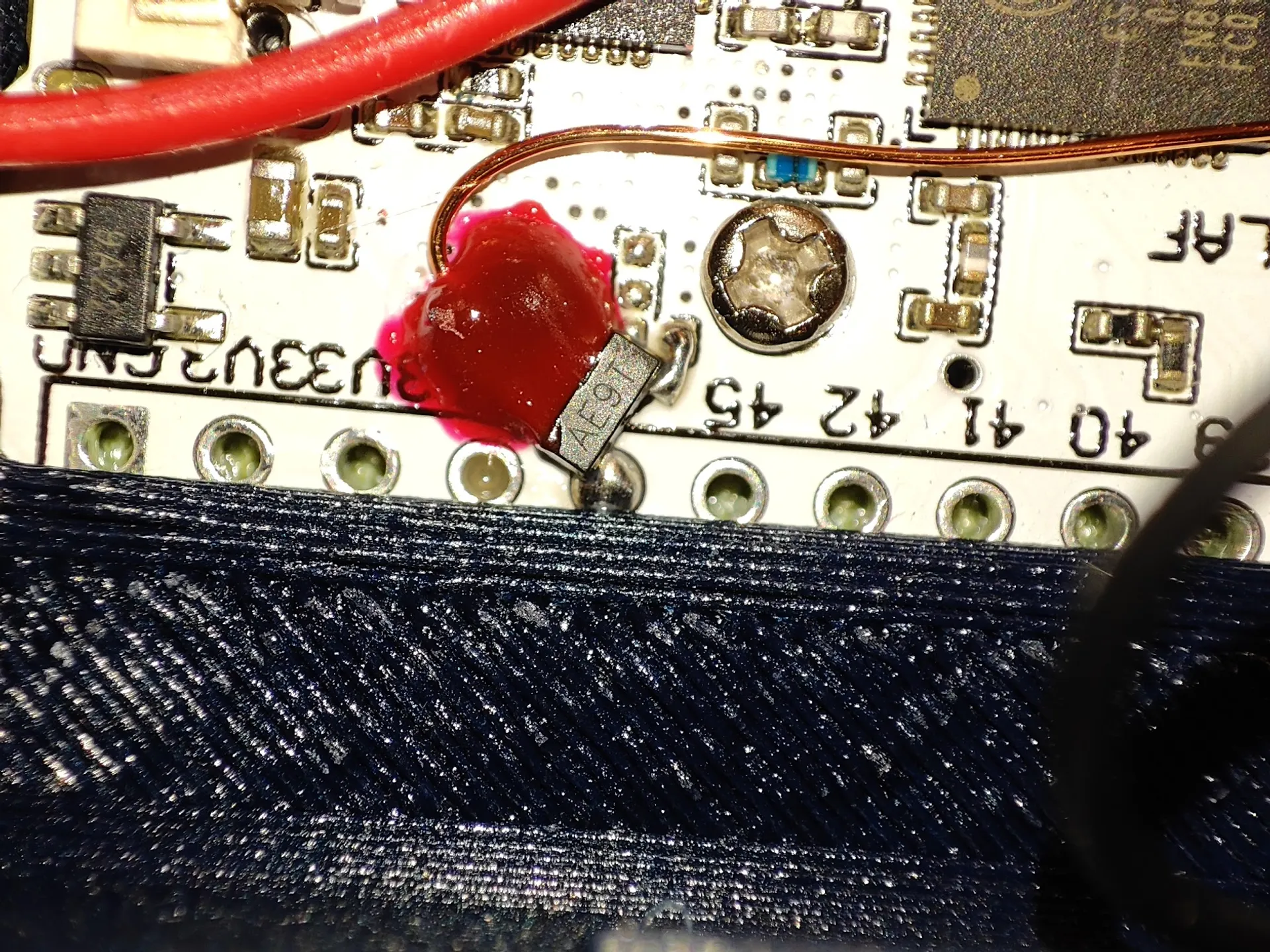
you can use some PCB glue, or hot glue, or uv hardening resin to fixate the contact point and take stress off the connection of the solder spots.
_____________________________________________________________________________________________________________
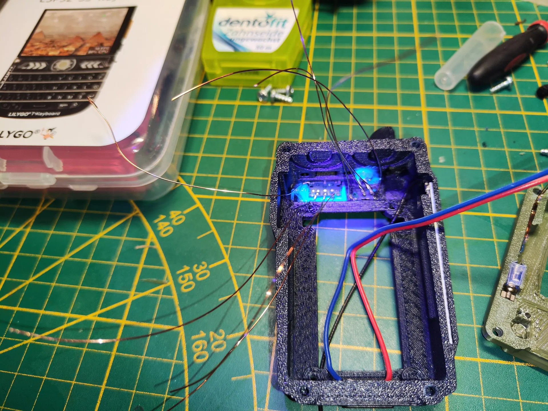
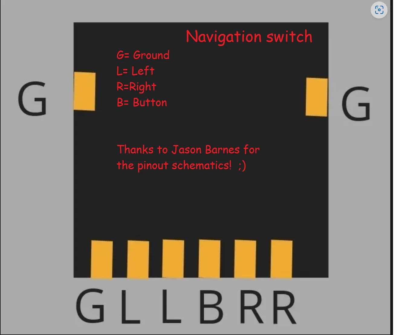
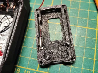
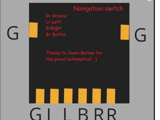
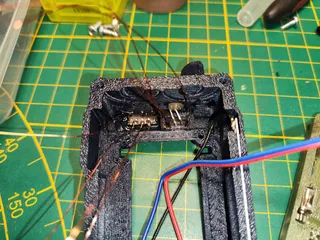
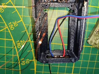
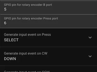
Navigation Switch and main power switch:
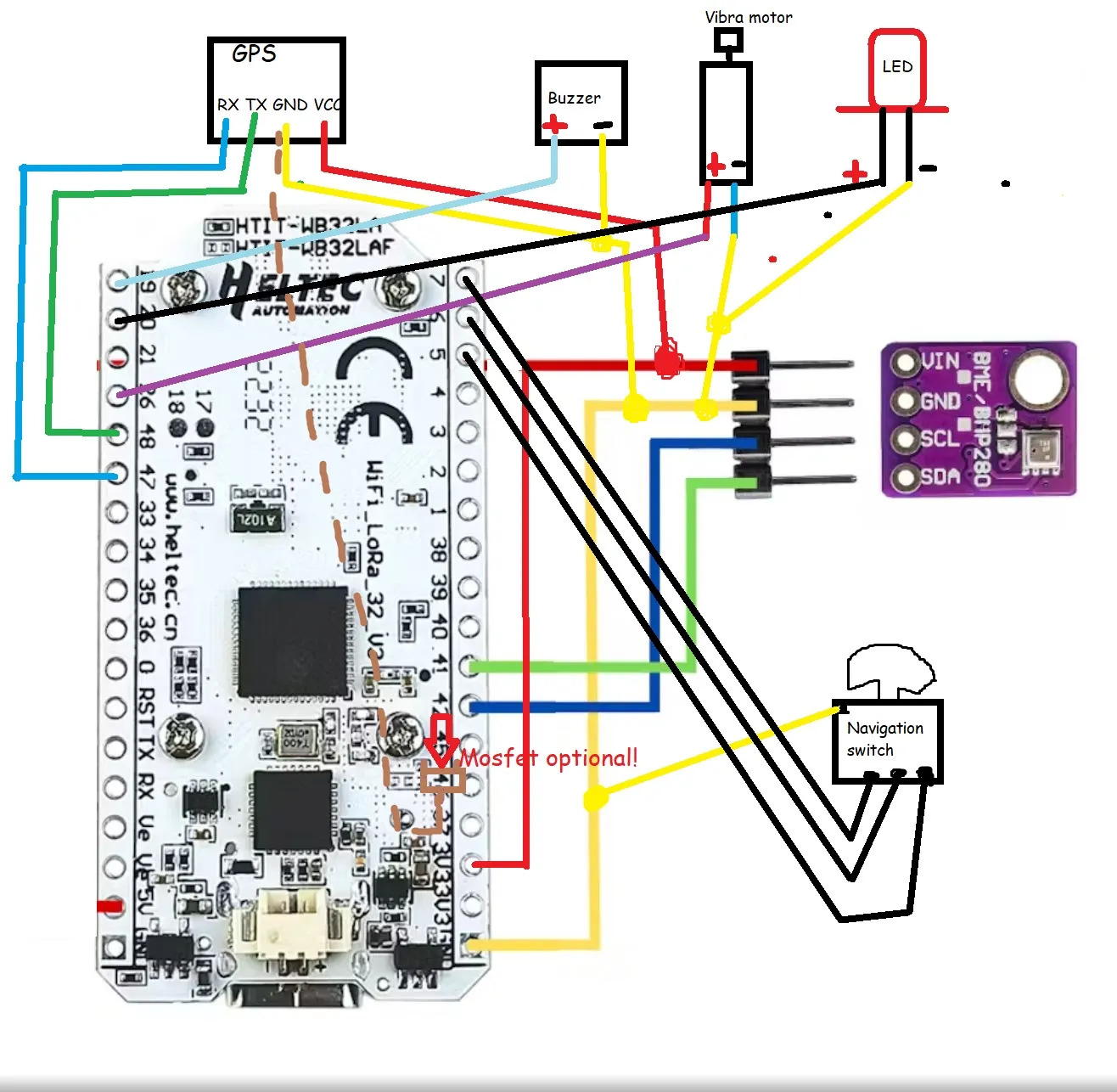
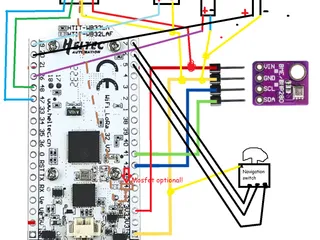
Navigation switch gets slotted in from the top. Use some glue to fix the switch in its printed frame. Make sure the switch is aligned all the way before gluing it down, There is a slight groove in the printed part, push it in until it hits the end of that groove. Solder wire to the ground point and 3 lower points ( check schematics picture)
over the Navigation switch comes the main power switch, I had some small screws at hand to mount it in without the need of glue. I used some very small screws I had left from a laptop repair. The switch goes in between the Minus cable coming from the batteries BMS to the heltec.
____________________________________________________________________________________________________________
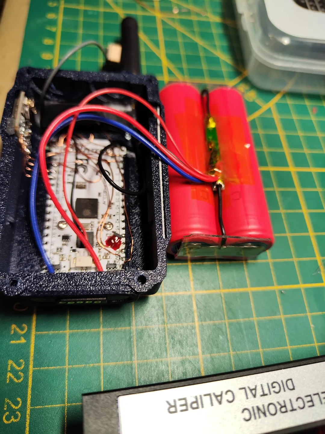
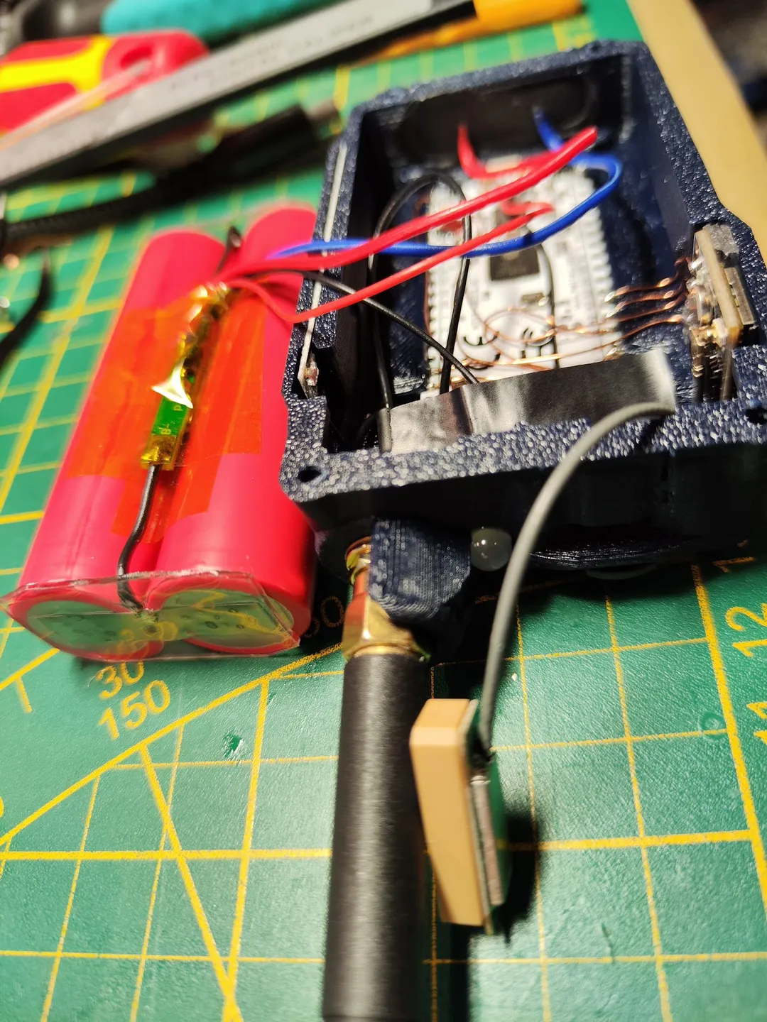
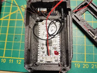
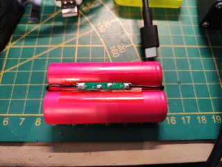
Battery pack and BMS ( Battery Management System)
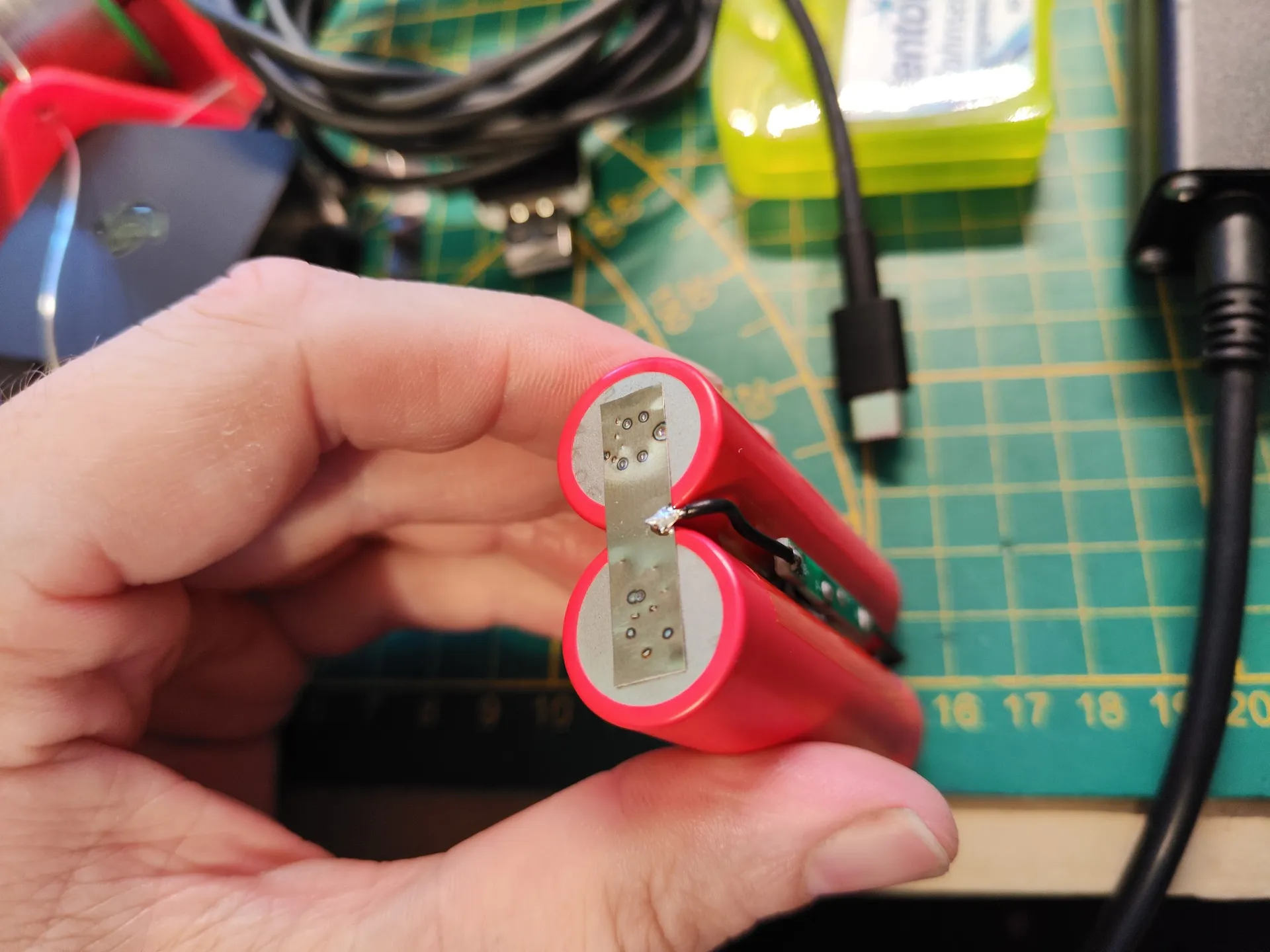
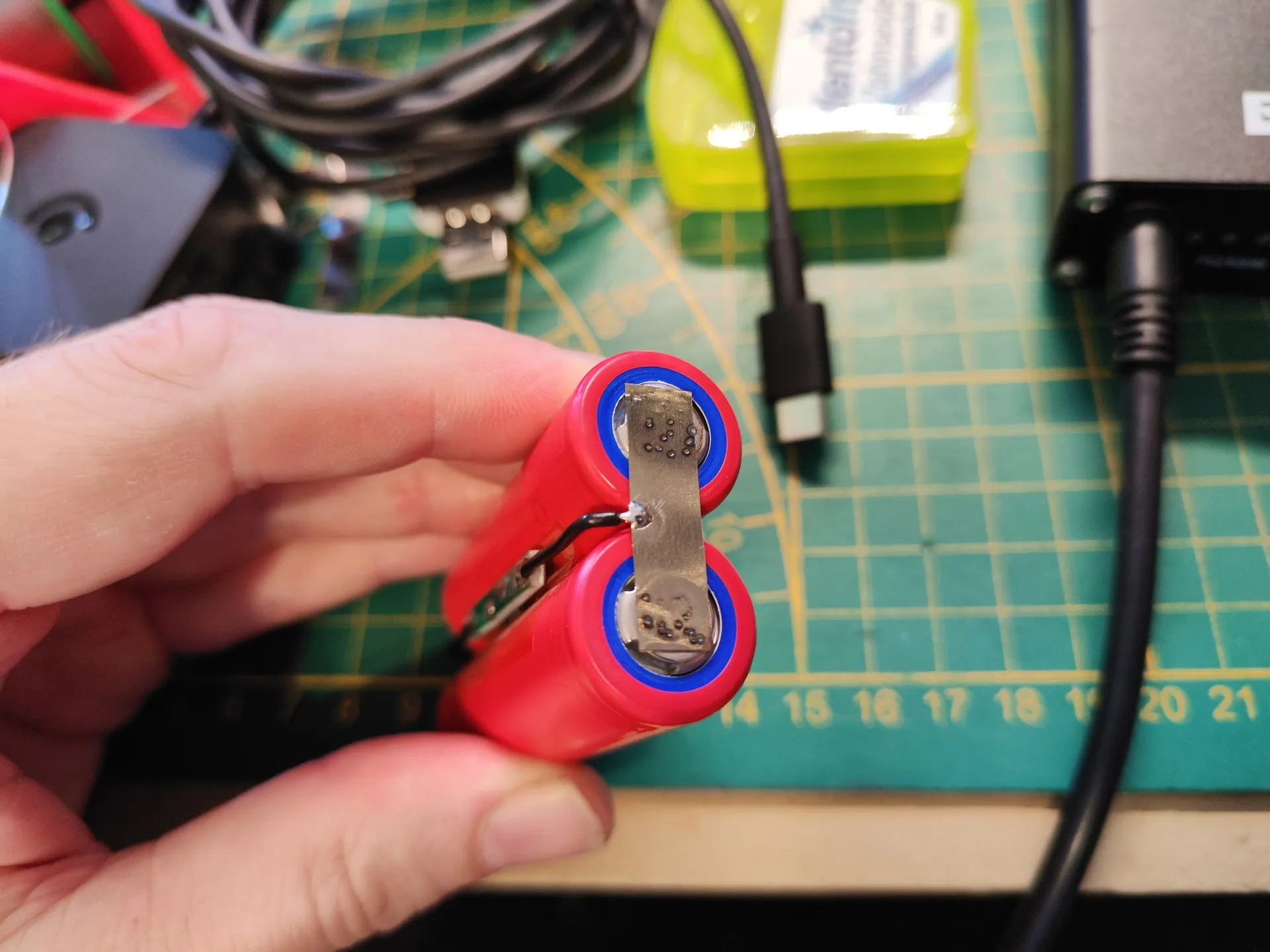
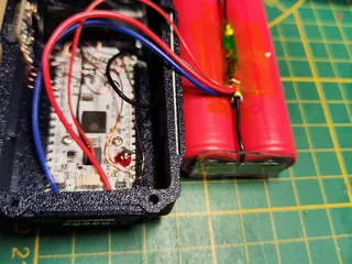
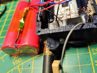
Before connecting 2 18650 Lithium Ion cells in parallel make sure both cells have the same voltage. If not you have to bring them to the almost exact same level by either draining or charging one of them. I would recommend to charge both to max as it is much easier. I f you have a spot welder and metal band always go this route over using solder and a soldering iron. ( its messy, big solder spots adds to the overal length of the pack and could cause fitting problems, heating up the solder points for to long is not great for the battery cell)
Connect both batteries in parallel, after that is done connect the BMS circuit to the cells. (check pictures) As it is a very tight fit its important that if you solder them togehter that there are no big solder drops on top and bottom as this could prevent the pack from fitting into the maximus and even worse if pointy, could puncture a cable and short things out!
___________________________________________________________________________________________________________
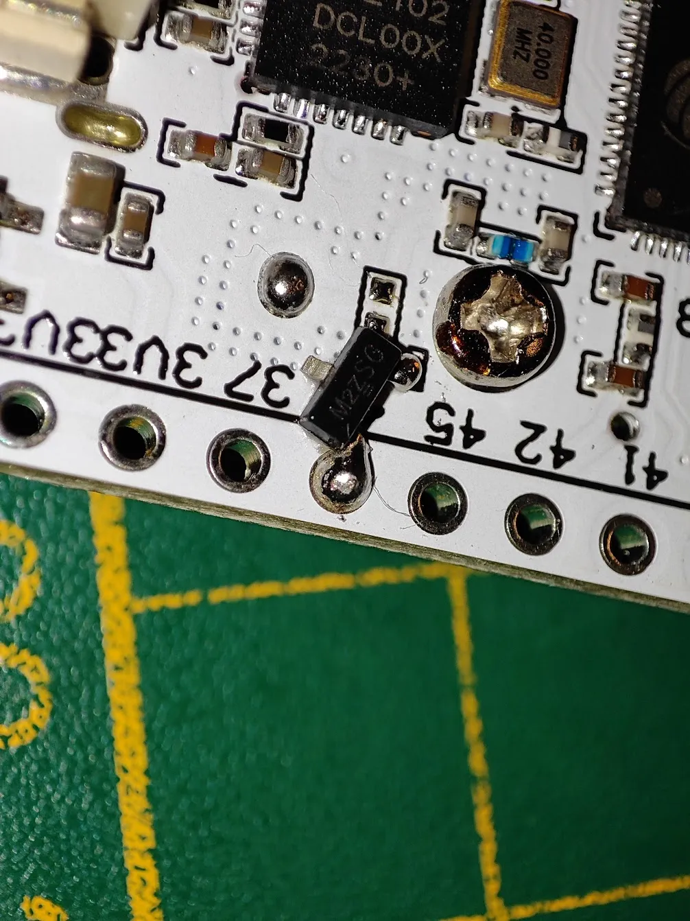
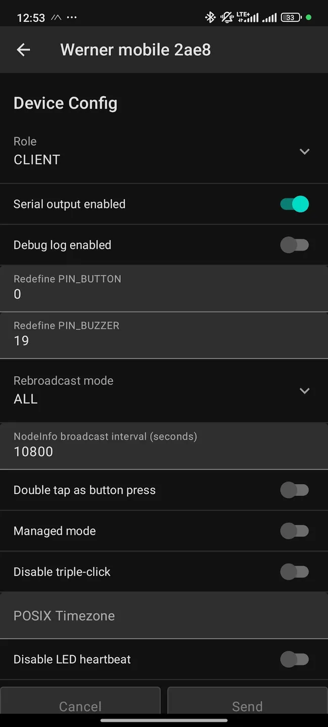
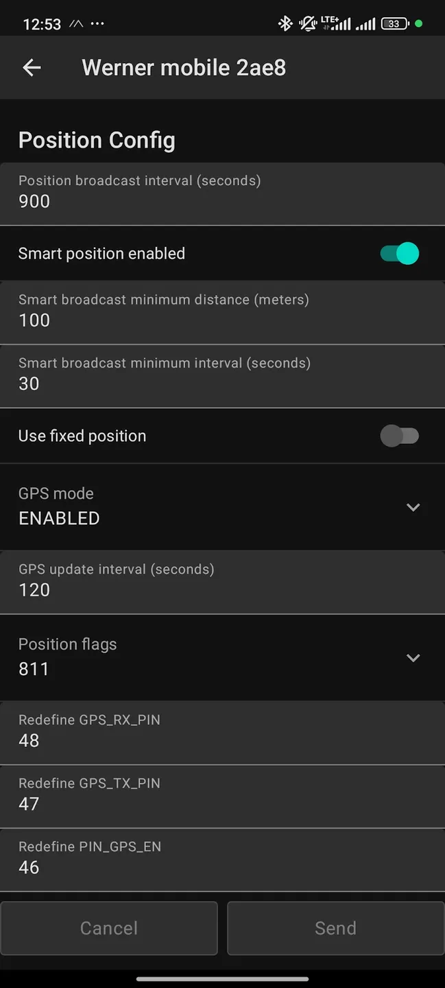
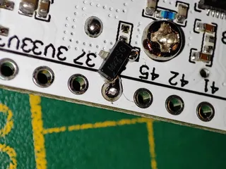
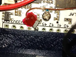
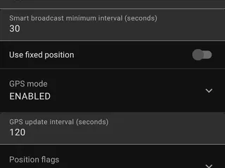
Mosfet controlled GPS power switch: (Optional but absolutely recommended!!)
With the GPS module turned on constantly it will almost drain your battery twice as fast!
Therefore it is advised to make use of the software controlled mosfet switch.
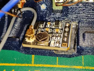
Check pictures, there you will find a schematic and pictures with the mosfet in place.
The ground pin from the GPS module is connected to the mosfet like shown on the picture.
There is a dotted line and a solid one on the rough schematic, of course ground only gets connected to either the mosfet or constant ground depending if you go for GPS constantly switched on or being controlled by the software based mosfet switch.
____________________________________________________________________________________________________________
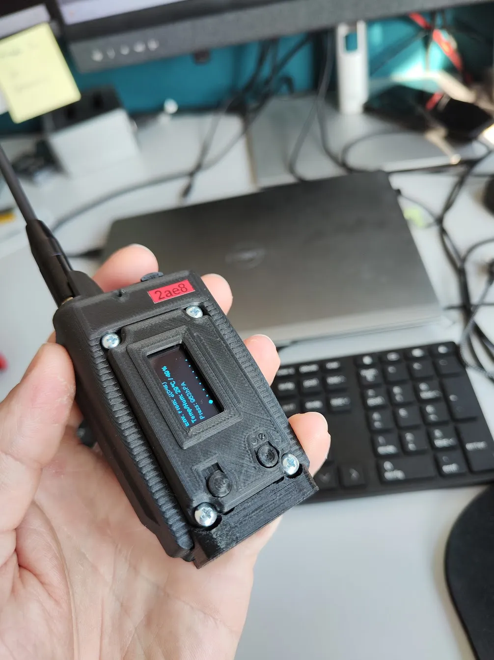
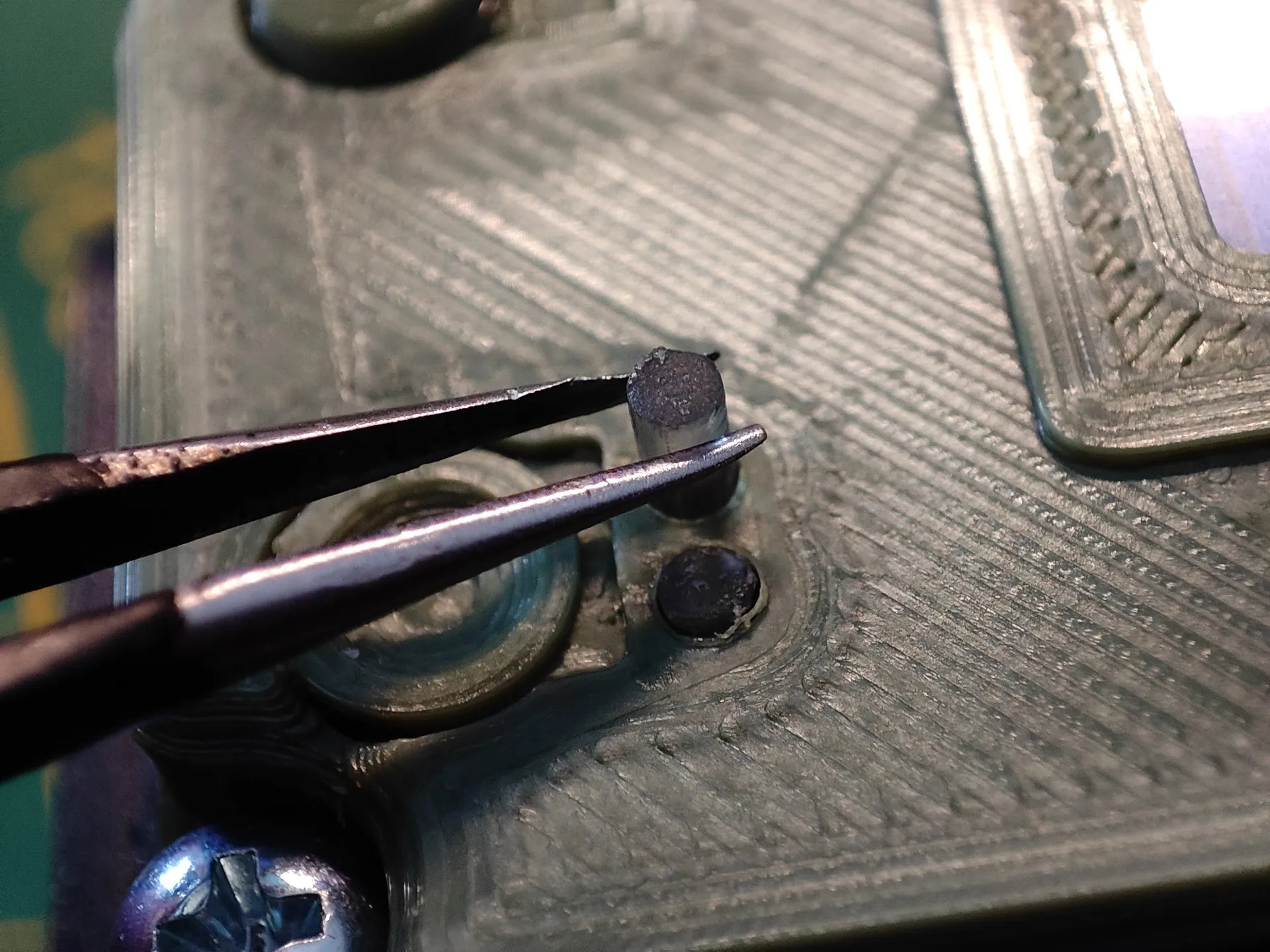
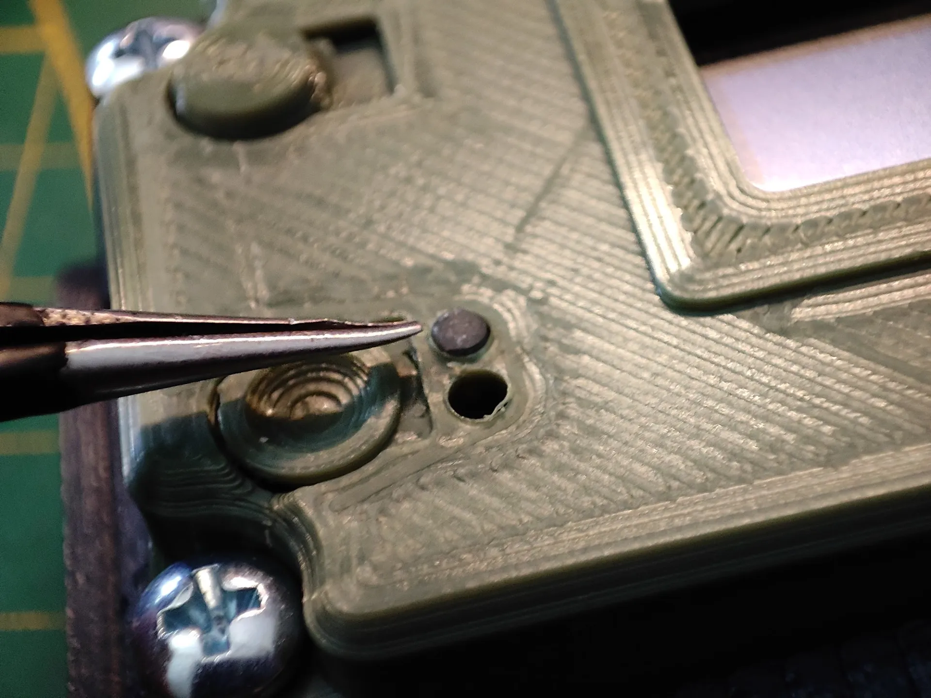
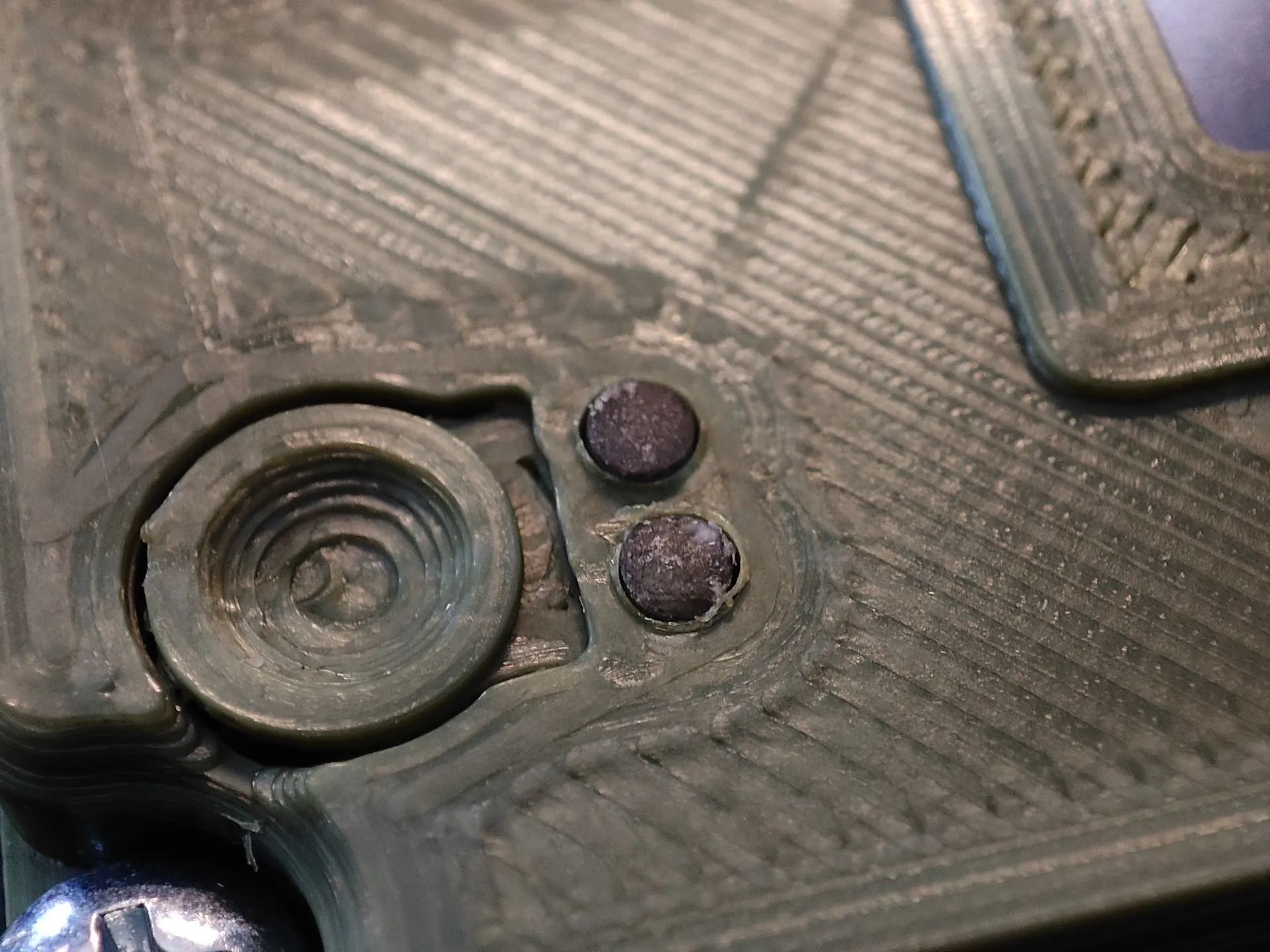
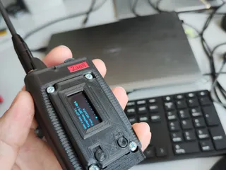
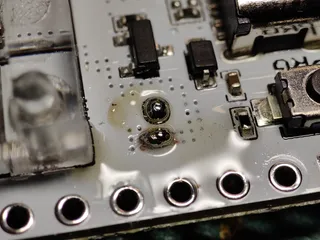
Charging LED / Status Led light bleeding:
With such nice fiber optical status lights you really wanna see the orange charging light properly separated by the breathing/ status light.
That for you simply glue a little piece of black sponge between the two LED s on the Heltecs Mainboard. (check pictures) that way you have two nicely seperated LED s with zero light bleed in between both.
____________________________________________________________________________________________________________
Parts you need for this build:
GPS Module ( Dual GPS + Beidou)
USBC 15 watt quick charging PCB: ( for desk charger + quick charging)
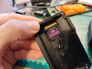
2 Telemetry sensor options, you only need one!!:
Telemetry sensor BME280 ( Temperatur, humidity, air pressure) !!!3.3Volt variant!!!
Telemetry sensor BME680 (Temperatur, humidity, air pressure, Air quality:
Much better antenna then the stock one the heltec comes with, select correct frequency for your region: (optional)
Mosfet to switch GPS on/off by software (optional): SI2312
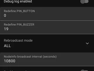
Buzzer: (8.5x8.5.3mm 3volt)
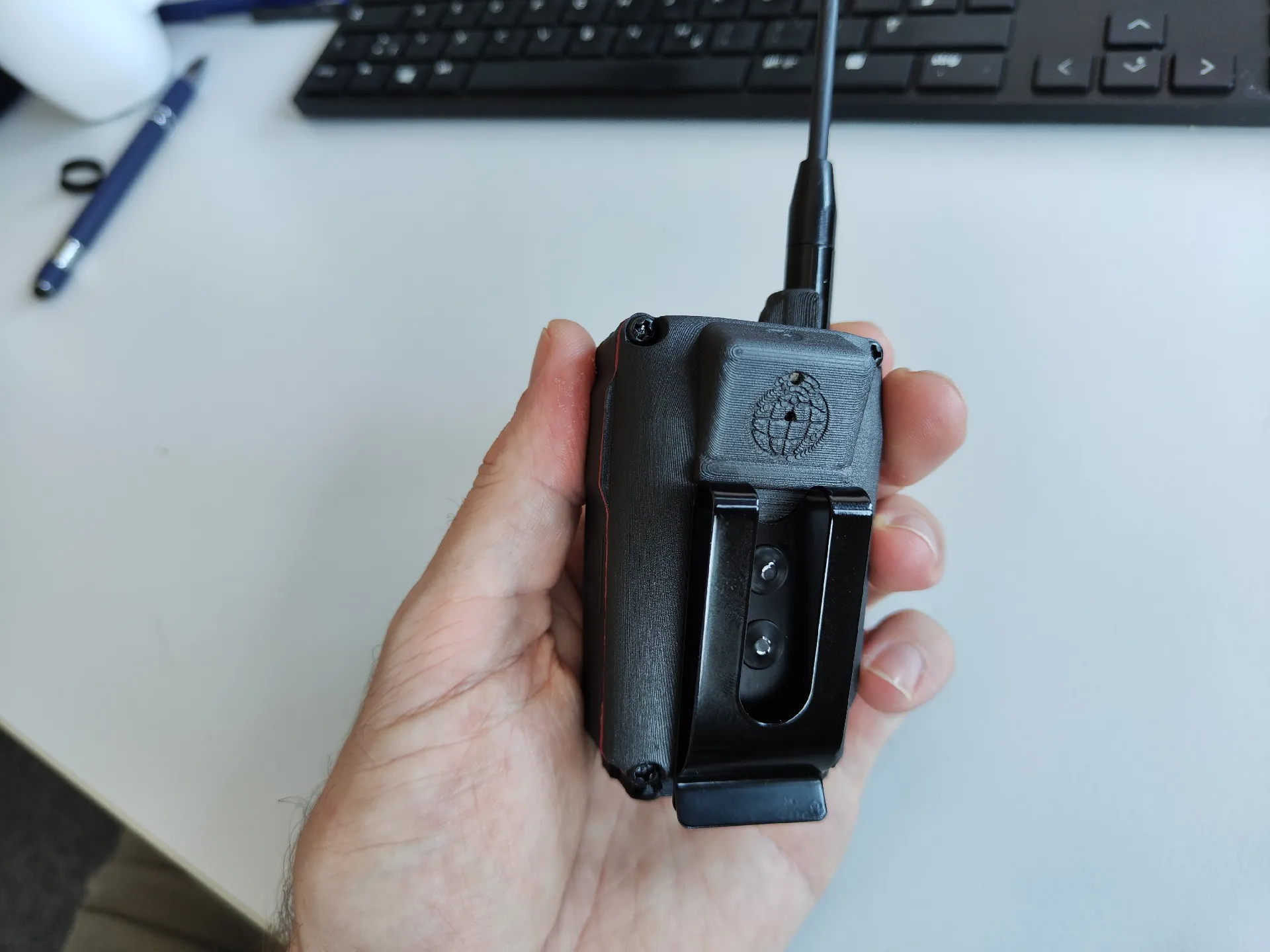
Metal belt clip including mouning rivets (2,5x5.5cm):
Vibrator motor:
Notification LED (RGB led): Diffused anode or cathode
Magnetic Pogo Pin connector ( 5 pin straight):
PCB wifi/bluetooth antenna:
Wiring cable 0.3mm:
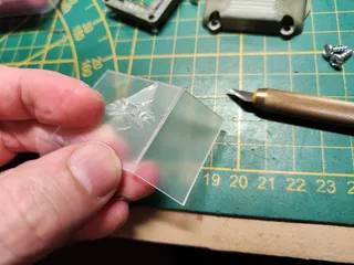
Acrylic glas (display protection) optional:
Navigation switch for canned messages K2-02 hollowed shell:
Main power Switch:
Case screws: M3 20 pieces 8mm length
2x 18650 batteries: I would recommend Panasonic NCR18650GA 3500mAh
Source them locally. Make sure both batteries have the exact same voltage before permanently connecting them in parallel!!
Battery management System (BMS): 3A
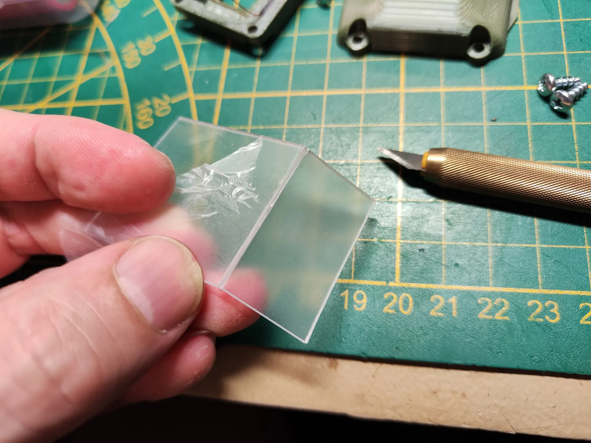
Additional Display protection: 35x20x1mm Acrylic sheet (optional):
The original design already featured space for 2x18650 cells, so I am rocking 7000mAh in mine!
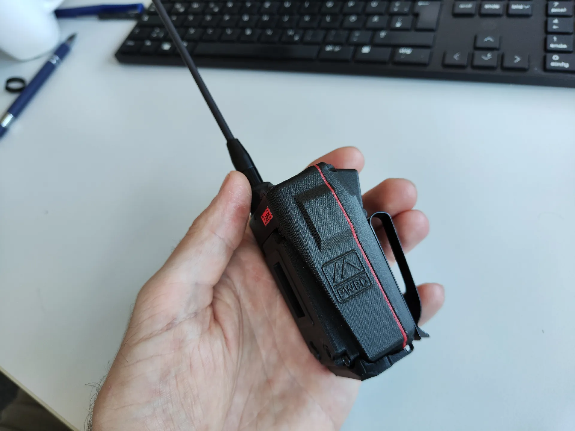
It also already utelized a manual main power switch (protected from accidental switching) which I of course kept. Sleep mode is fine but off is off.
______________________________________________________________________________________________________
Changes and upgrades I've done to the original Design:
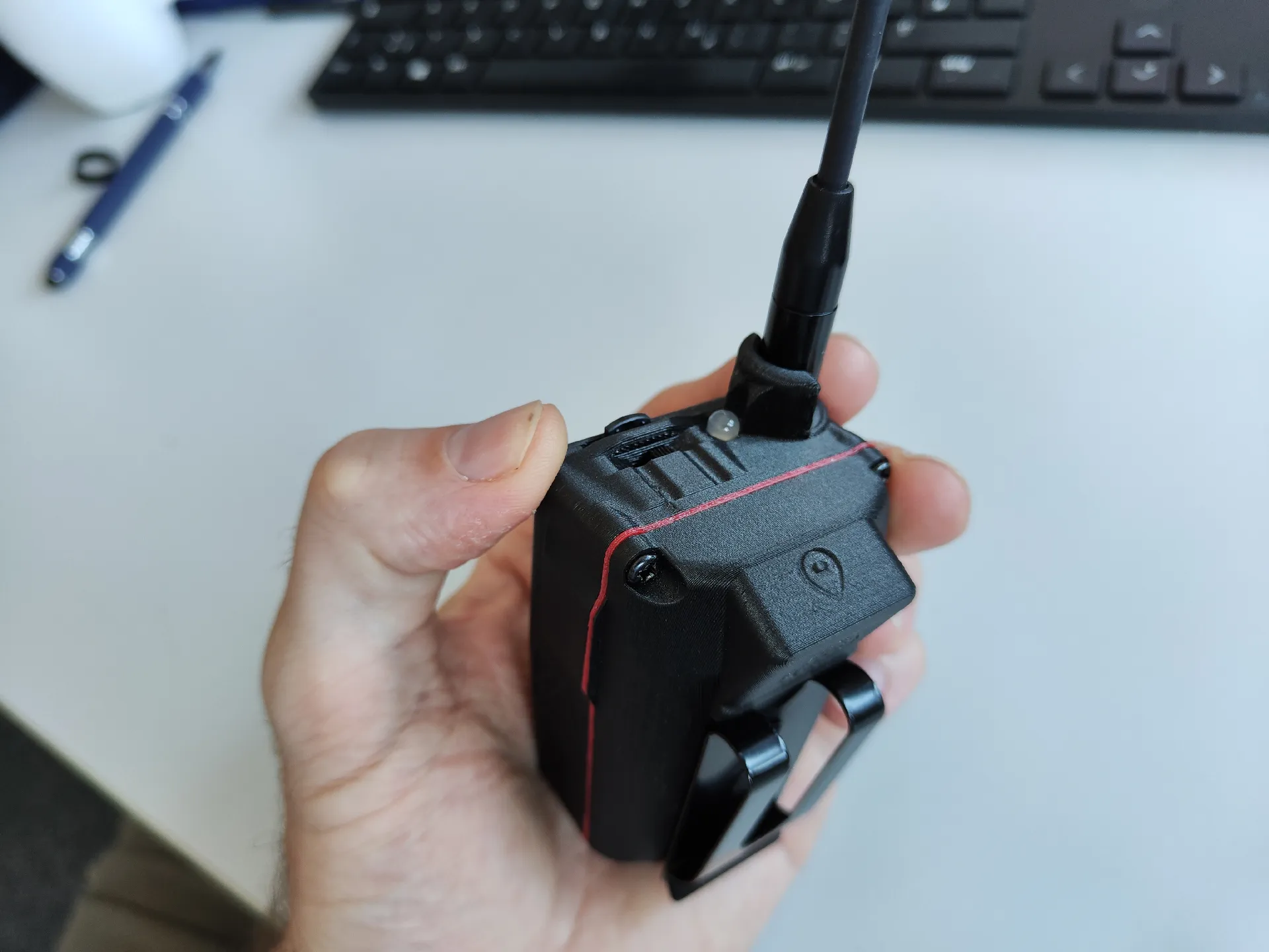
- Added antenna base protection
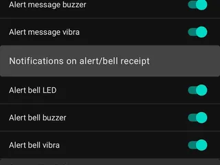
- Added Notification Buzzer
- Added Notification vibrator
- Added Notification LED
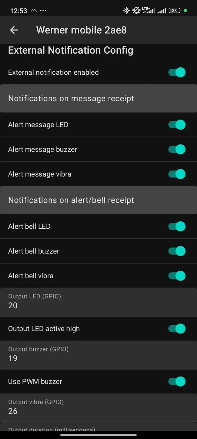
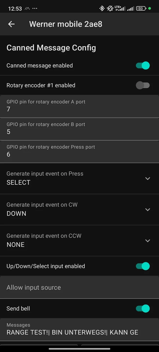
- Added Navigation Switch for canned messages
- Added GNNS/ GPS Module ( Beidou+ GPS)
- Added environmental Sensor BME 280/ 680 (temperature, humidity, air pressure,(AIQ))
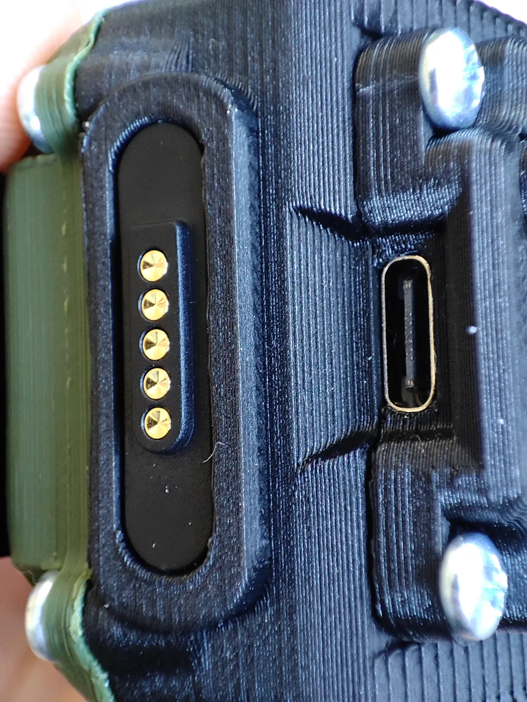
- Added Magnetic pogo pin connector for 15 watt quickcharging
- Added tethered TPU foot ( protects the magnetic pogopin connector+ USB C port)
- Added TPU sealing for back cover ( more for looks then actual watertight ;) )
- Replaced tiny wifi/Bluetooth coil antenna with external PCB antenna with great range!
- Mounting point for Metal belt clip
- GPS Power on/off switch by meshtastic software and mosfet
- Acrylic 1mm display protection
- Lifted user button for better feedback
- Transparent filament fiber optics system status lights
- Cleared out back cover so 18650 cells connected with metal band ( spot welded) can fit
- Wifi/ Bluetooth antenna cable routing channels in front face plate
- Mounting point and cable routing for vibra motor in front face plate
- Deleting original coil antenna cutout
- Added SMA hex nut key (with the antenna base protection in place its otherwise hard to tighten the nut properly)
- 15 Watts Desk charger (15 Watts external quick charging compared to 3.5 Watts from heltec V3 onboard charging circuit)
Tags
Model origin
The author marked this model as their own original creation.