DIY Joystick - Parametric

Description
PDFI wanted a joystick i could use with games like farming simulator or flight simulator, but i didn't want to buy one since i am planning to incorporate it into a farm sim side panel. And i find it fun making my own stuff.
Printing:
The only models that require supports are the ones that have 3mf files.
Parts:
- Arduino Pro Micro: Or any Arduino with the ATMega32U4 chip.
- Hall effect sensor x2: Make sure the sensor you are buying is linear. The one i have is S49E, but there are multiple different models.
- Bearings x4: If you are planning to use the stock .stl files provided without modifying the parameters in CAD then u have to use 625zz bearing. However if you have different bearings just open the CAD file and change the bearing dimensions to suit yours.
- Springs x4 or x8: I used two 25 mm springs for each corner, but you can use whatever springs you want based on the stiffness you want, you could even use rubber bands.
- Jumper wires
- Dupont connectors
- Screws: You need 4 screws that are the same diameter as the bearing hole. I used m5x12. And for the joystick assembly and base i used six m3x16.
- Magnets: I used a round 8x4.5mm magnet. This can be changed.
- Buttons (optional): I used 6x6x6mm push buttons
- Joystick module (optional): I used HW-504
Tools:
- Soldering iron
- Crimping tool (optional): You can crimp the connectors with pliers.
- Hot glue gun or CA glue
- Thread tap set
- Double sided tape
Assembly:
I also recommend using the assembly in the onshape file as reference. For this you don't need an account.
You can change the pins used in the code based on your preference.
Base:
Print all the parts for the base.
Take the Roll, tap the corresponding threads into each hole (except the two bottom ones) based on your screw's thread. Cut away or sand down any high spots that are left around the holes.
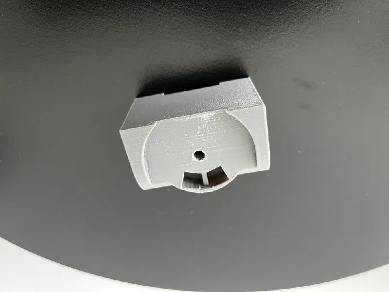
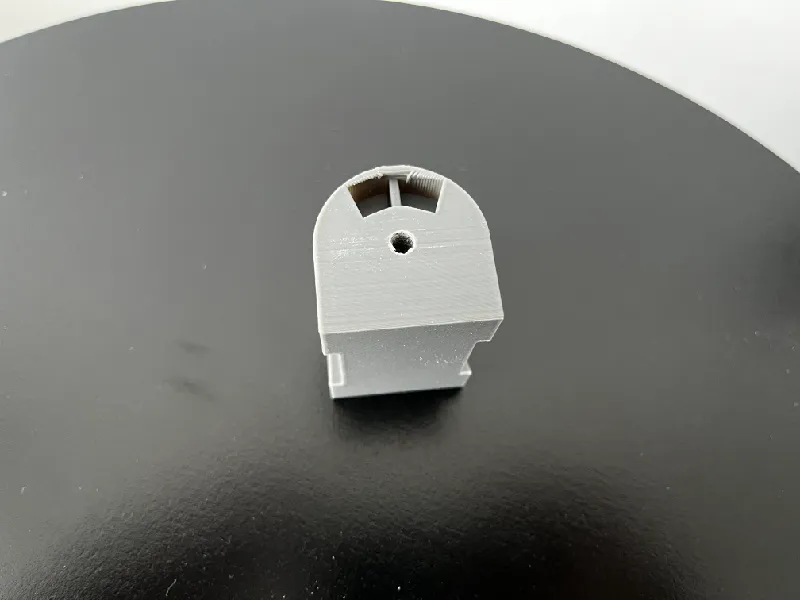
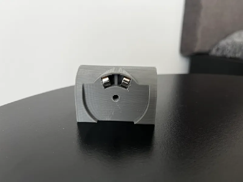
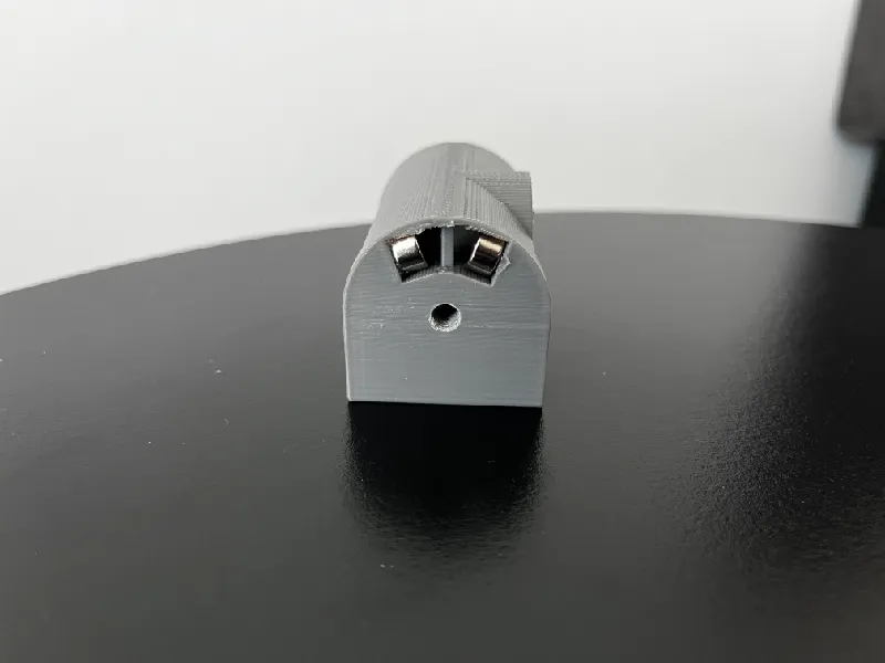
Glue magnets into the opening like it is in the image below. I used hot glue and pressed it in place. Make sure the polarity of the magnets is reversed on the second magnet. Take 2 magnets stick them together, glue one of them pointing so that it pulls the second one to it, turn the second one around and glue it to the other side. If a some hot glue flows out cut it off.
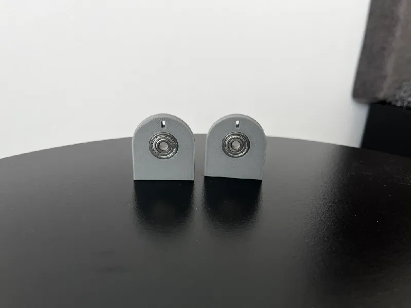
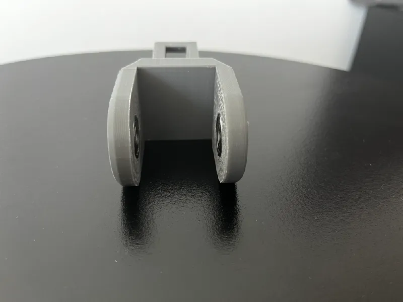
Take the Pitch and Roll holder and press the bearings into the openings. For Pitch I recommend sanding down the surface around bearings before you press them in, to make sure the movement on Roll is smooth.
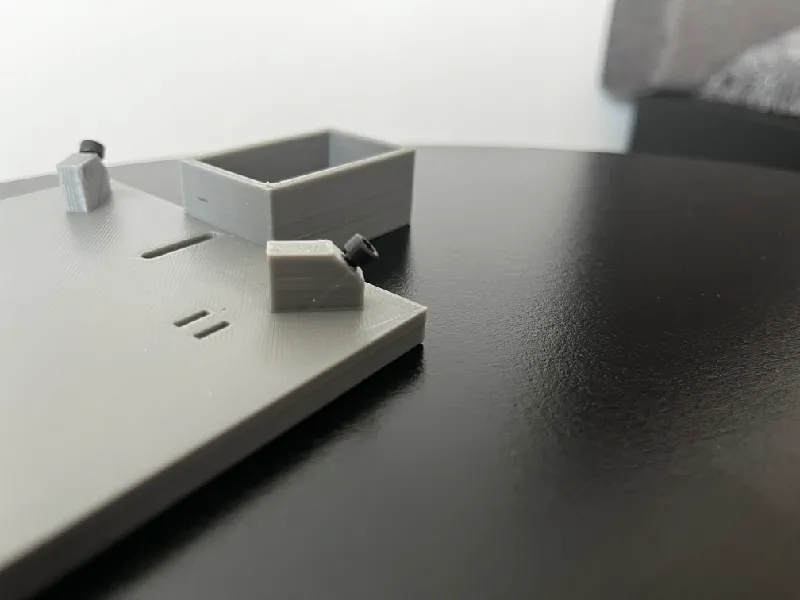
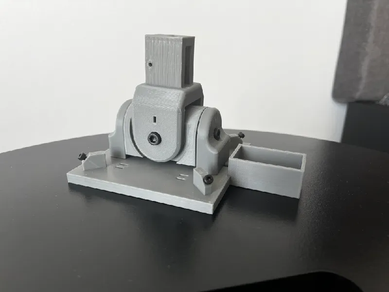
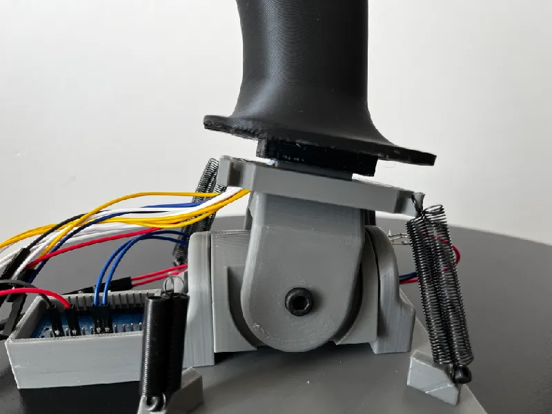
Take the Base and screw the screws into the 4 holes around. Make sure they aren't tightened all the way, but there is a bit of space left, like in the picture.
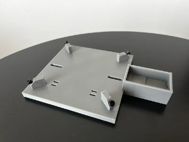
Now screw the Pitch and Roll holder to the Roll, make sure Pitch has the hole above the screw on the side that has magnets and screw the whole assembly to the base using the screw holes on the bottom of Roll holders. Make the assembly is somewhat centered on the screw rails.
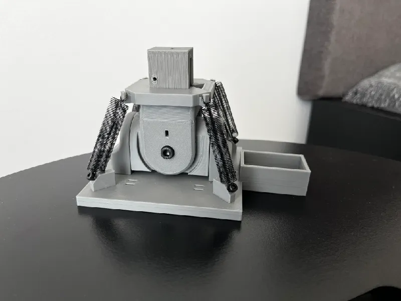
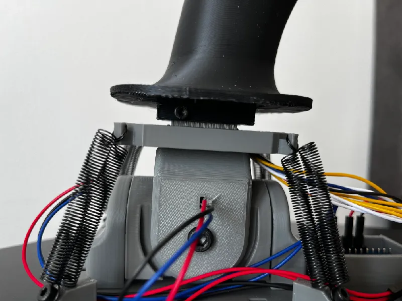
Add the spring holder on top with the notch facing the notch on Pitch. Put the springs on, like you see below. I used 8 springs, 2 per corner since it makes the self centering a bit heavier, but this depends on what springs you got.
Insert the hall effect sensor inside the holes until it cant move forward anymore, pull it a tiny bit back and glue it from the outside with hot glue. Solder the wires to the contacts based on the datasheet for your model. For S49E i used, this is the datasheet.
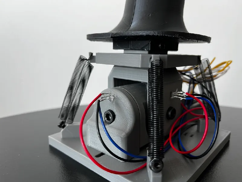
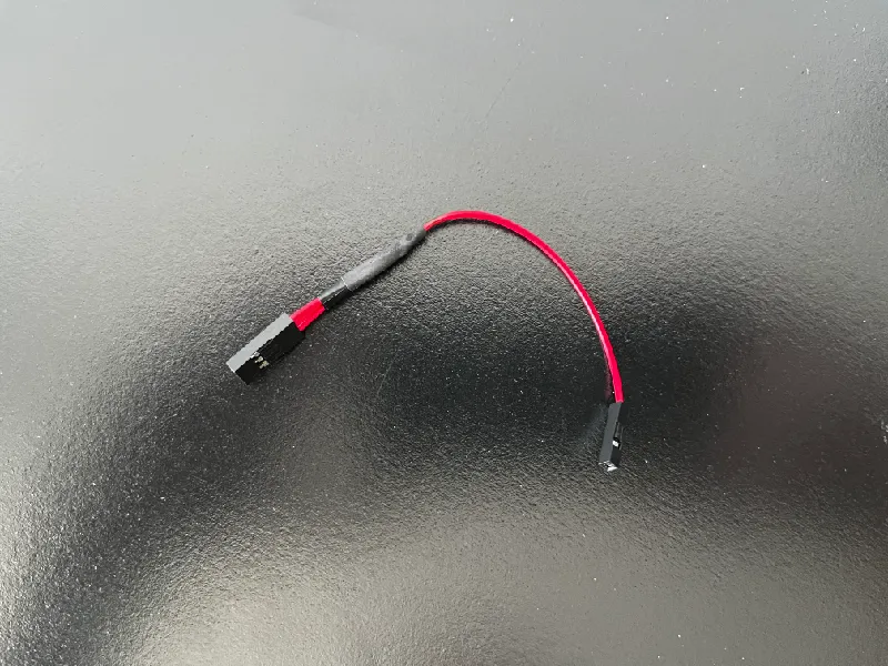
Connect the OUT wire of Roll to A0 pin and OUT wire of Pitch to A1 pin. For the power and ground i made these. It's 3 wires soldered to a single wire. This goes to the VCC pin, the equivalent for ground to GND.
Joystick:
Print all the parts for the joystick. If you want you can design your own joystick as well.
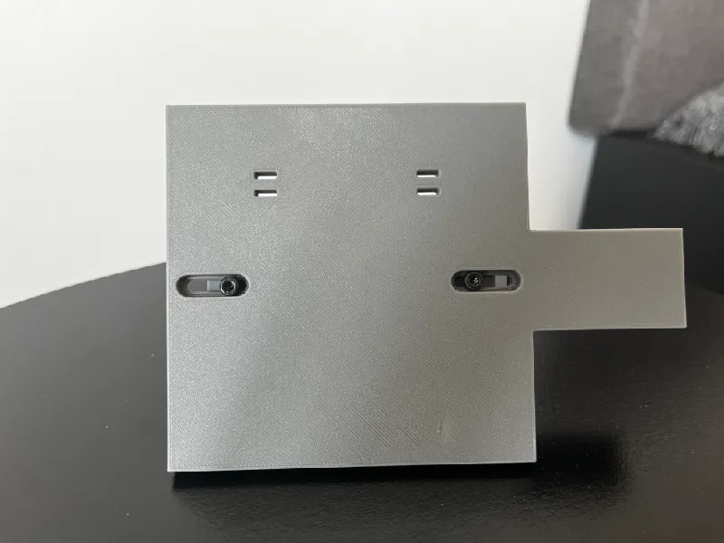
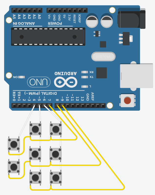
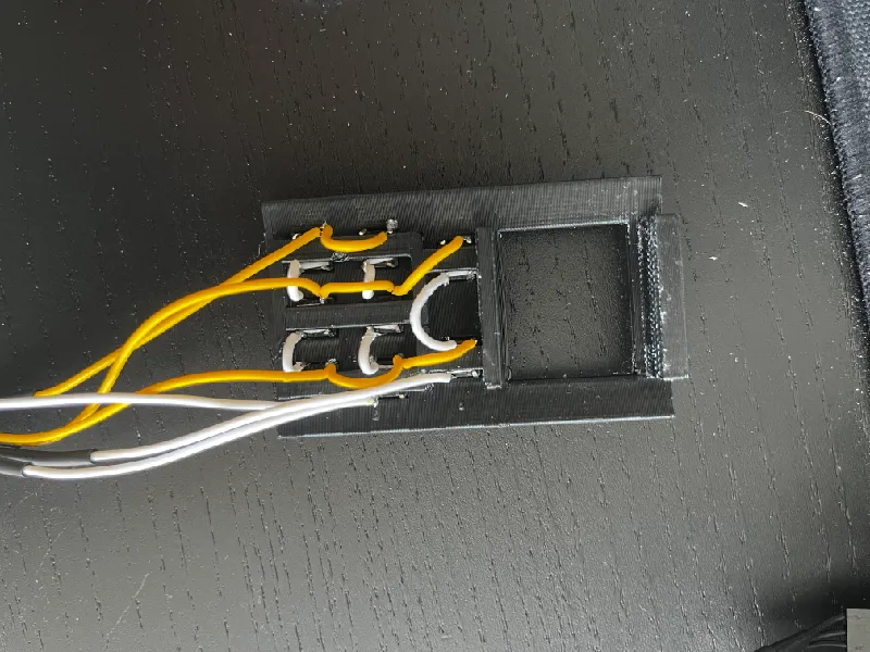
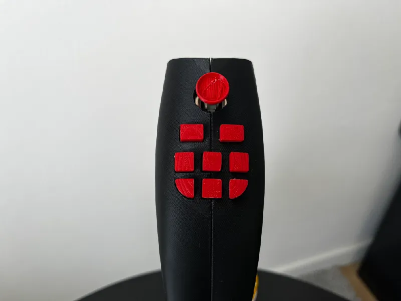
Put a small square of double sided tape on the bottom of each button and insert the 8 buttons into the Backplate. Solder them in a matrix like on this circuit. The Arduino Uno is just an example since tinker-cad doesn't have other Arduino boards. I used pins 4, 5, 6 for the columns (white) and pins 7, 8, 9 for the rows (yellow).
Tips:
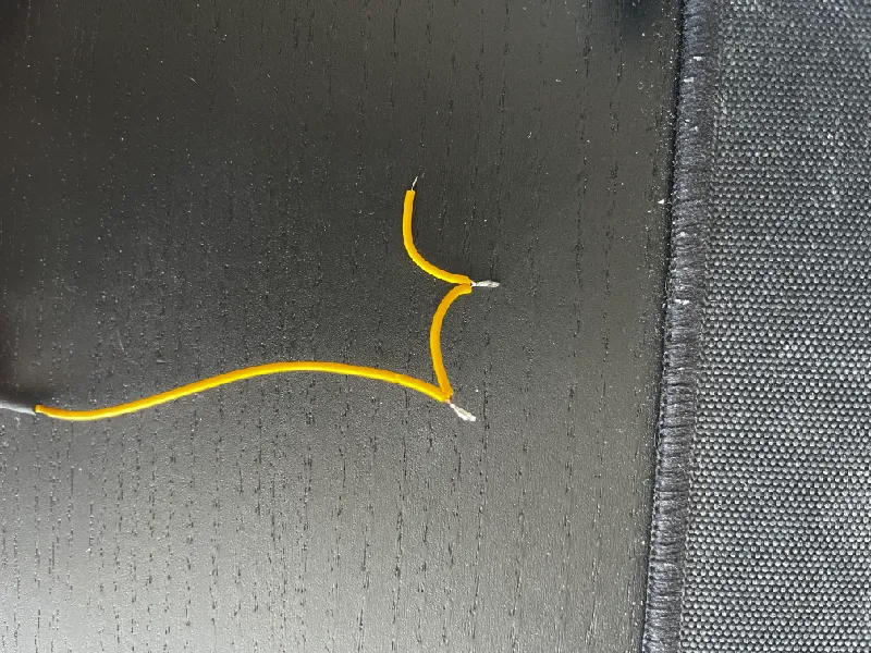
For the yellow wires I winded them up like shown below and soldered the contacts. Now its a lot easier soldering them to buttons in the tight space.
After that if you also want to install the joystick module. De-solder the pins and solder the wires directly to the contacts, since with the pins it doesn't fit very well. They are connected to the pins on arduino like the following: SW: 10, VRX: A3, VRY: A2 and power, ground. Stick the module with double sided tape to the 2 walls above the buttons. I recommend looking at the onshape assembly to get it right.
Insert the backplate into the notches on the joystick halves. Route the wires out around the screw holes. Once it all fits, screw it together. Slide it onto Pitch with the wires going through the hole.
Screw the joystick to the base.
You can now hot glue the button caps and slide the joystick module cap in. If any of the buttons don't fit just sand the walls of the button a little.
Adjustments:
If the joystick is not centered on the pitch axis you can unscrew the screws a little bit on the bottom of the base and move the assembly forward or backward so that pitch is centered and tighten it back.
Software:
Clone the GitHub repository or just copy the code from main.cpp and send it to your Arduino using your preferred way. I used PlatformIO.
Calibration:
Windows:
win + r → joy.cpl
Click on your device properties and calibrate. This will set the center point and limits.
Linux:
I recommend jstest-gtk which also has calibration option.
Credits:
The models i used in the assembly as an example:
Tags
Model origin
The author marked this model as their own original creation.


