Xbox Controller Accessibility Mod


Description
PDFUpdate 2.2.3!
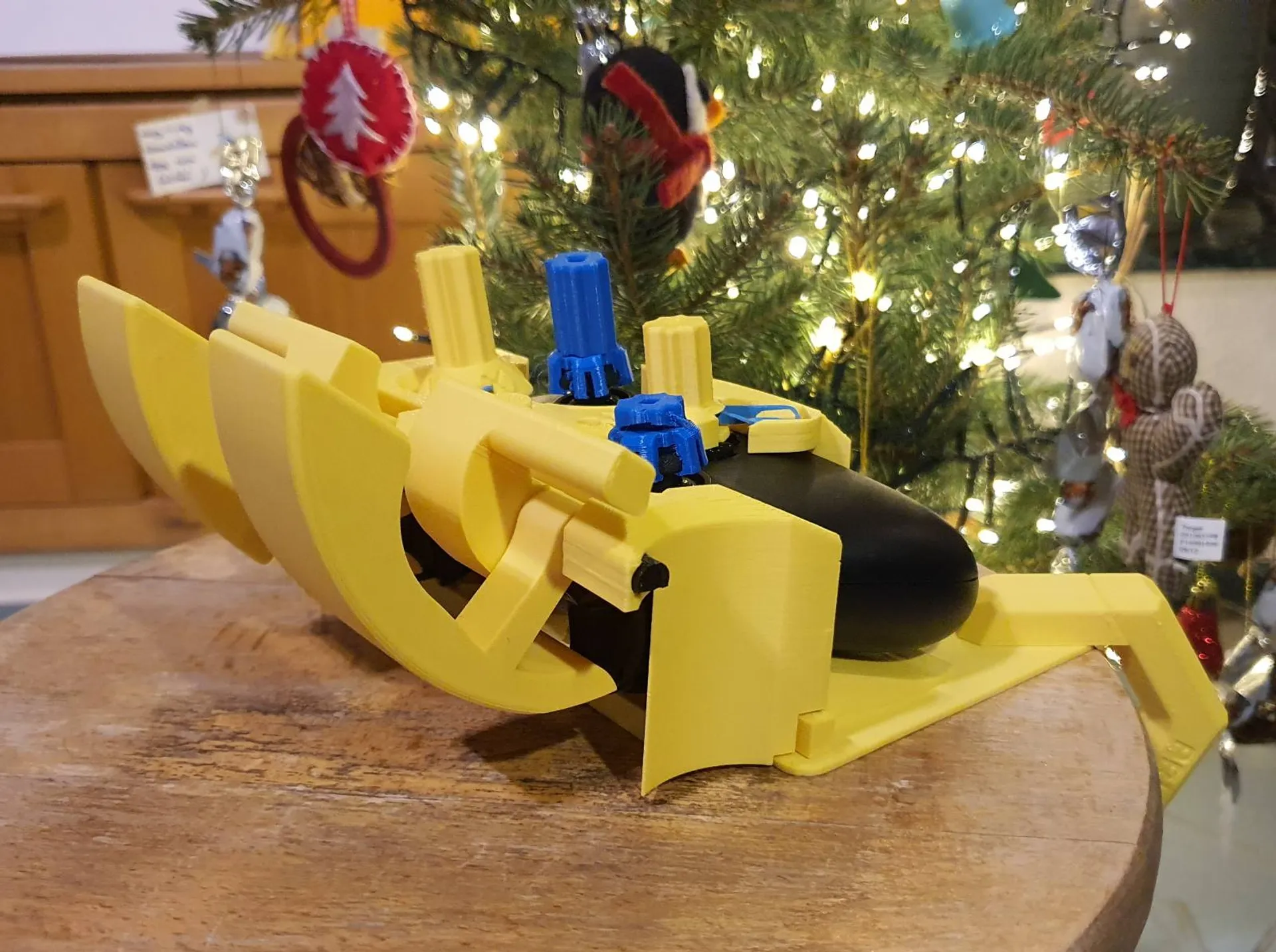
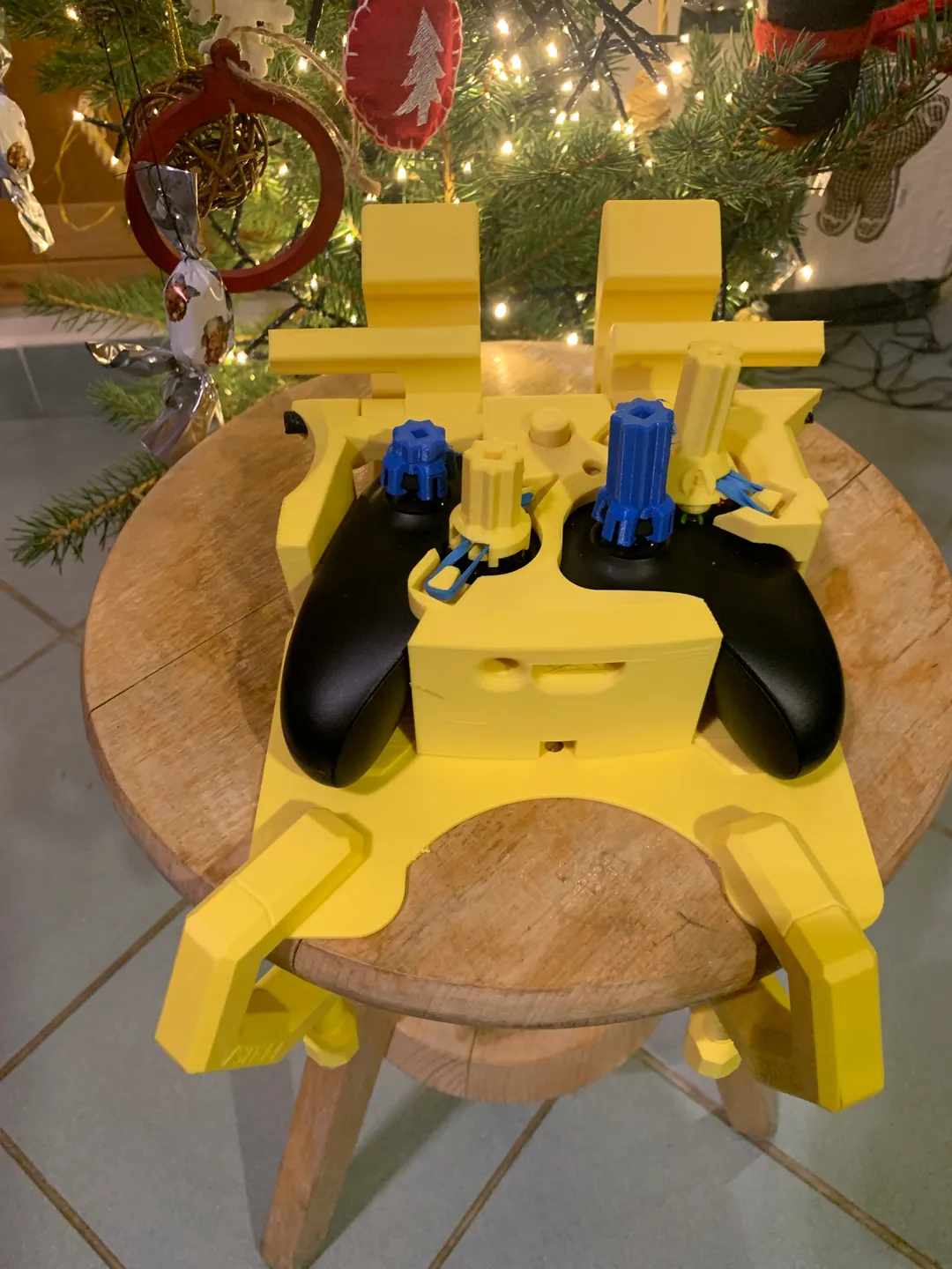
This new version stops the triggers from flipping onto the controller, makes it print way cleaner, makes the joystick clips slightly better, adds two parts that make it possible to strap to one's leg and cleans up some ugly chamfers.
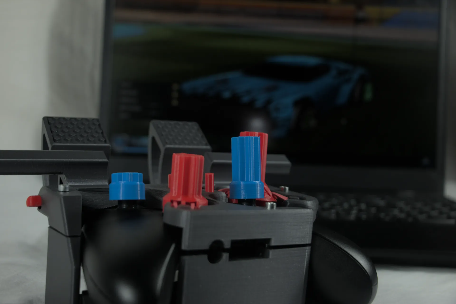
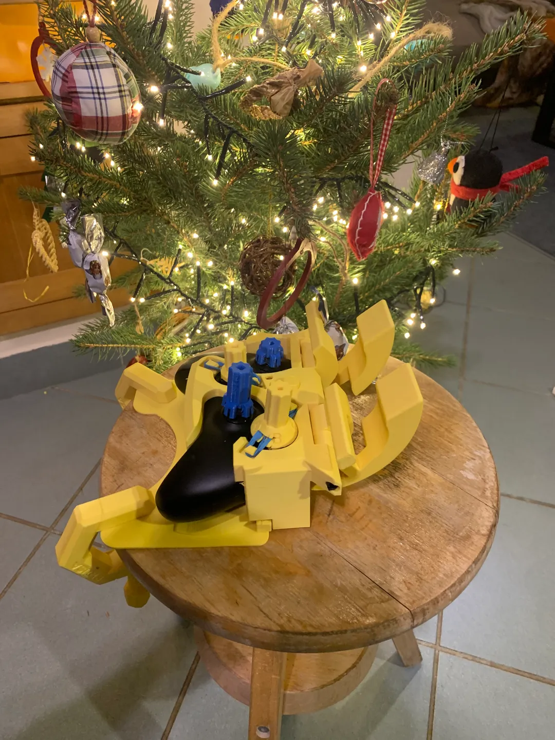
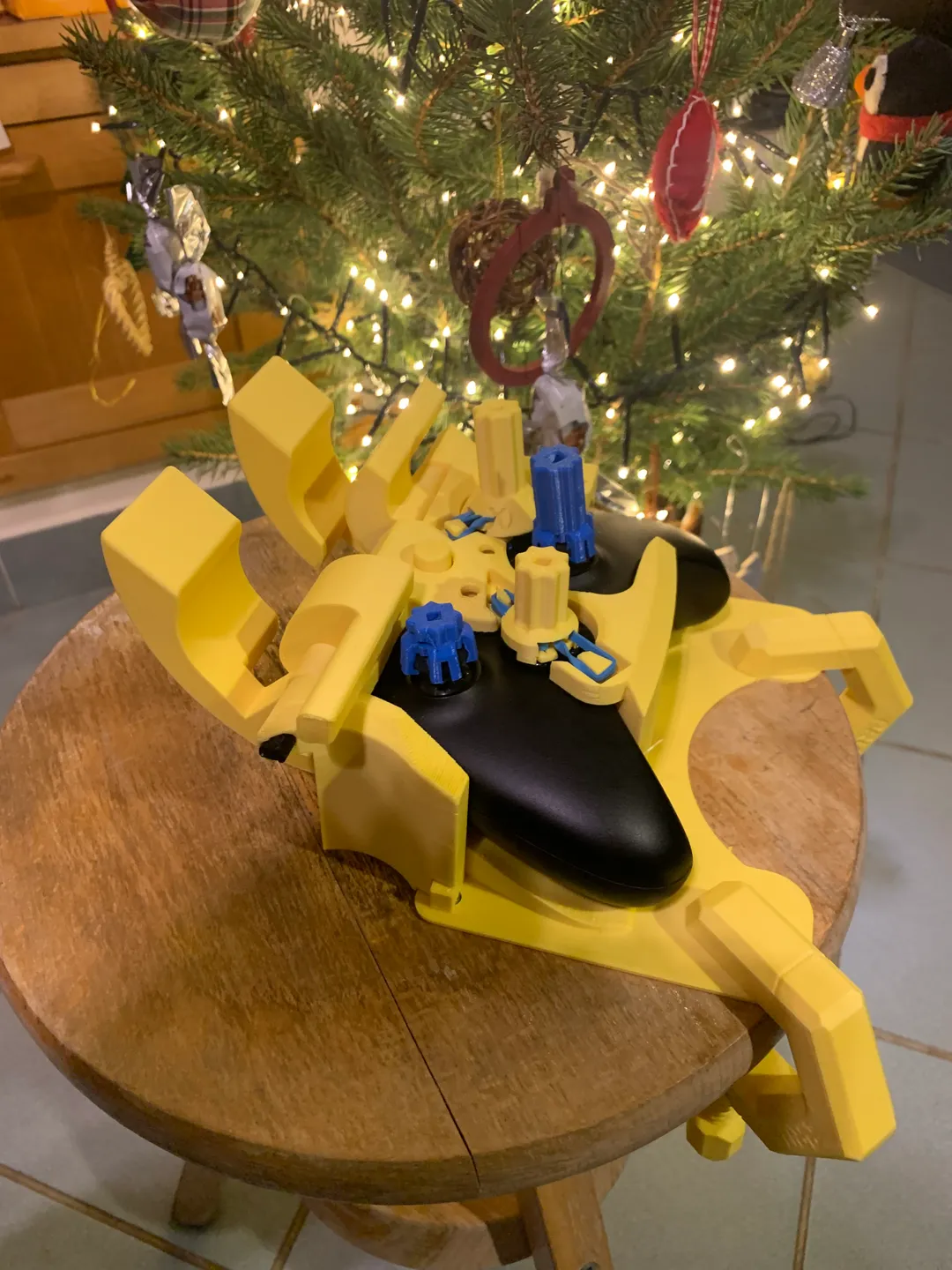
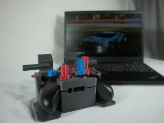
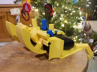
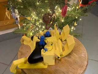
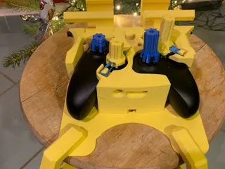
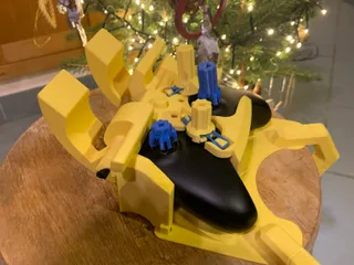
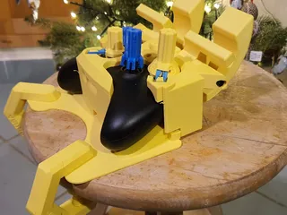
The D-pad and the buttons are joystick based, and the triggers are enlarged to ensure accessibility for everyone.
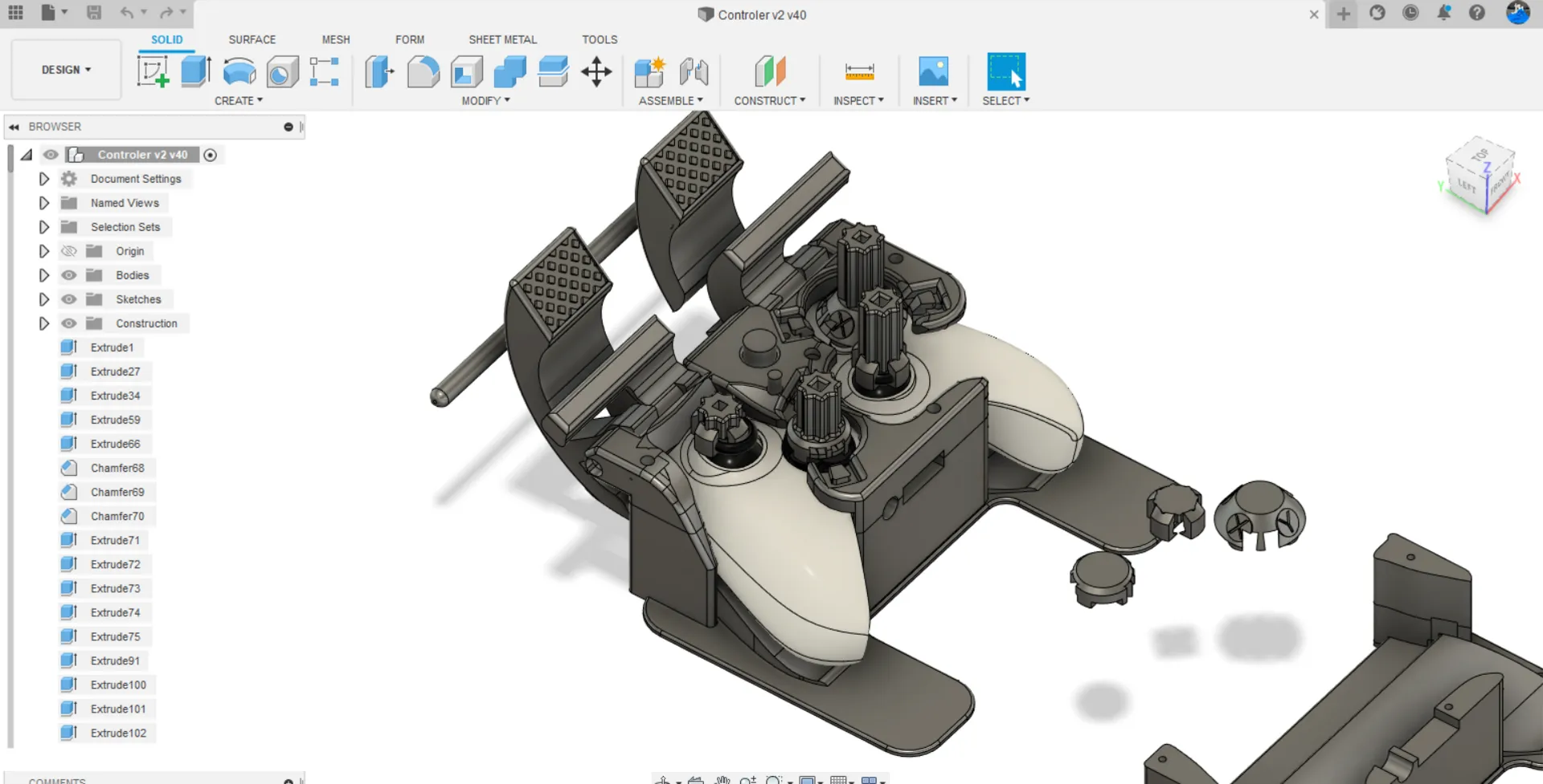
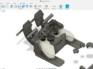
I have uploaded the .f3d files and shortened versions of the joysticks, so they can be easily customized even in Tinkercad. (Please note that the “button pusher” joystick only works reliably if its stick is longer than ~15mm).
Printing:
I recommend using good quality PLA, or just normal PETG for everything except for the “Joystick Grabber”-s. NYLON would be ideal for the “Joystick Grabber”-s but if its not available any FLEX will do. In either case, the bottom ~1mm of the “Joystick Grabber”-s may need to be cut off in your slicer, depending on your printer’s tolerance. (Make sure that its a tight fit onto the actual joysticks). It can be printed without supports, as long as your bed adhesion is reliable, so all the details stick down. The small holes behind the rubber-band holding pegs are there so that an M3 screw or a small rod can replace the pegs that hold the rubber band pegs.
My print settings:
0.2/0.3mm layer height
5% infill because I was just prototyping, but a little more can't hurt
Extra parts:
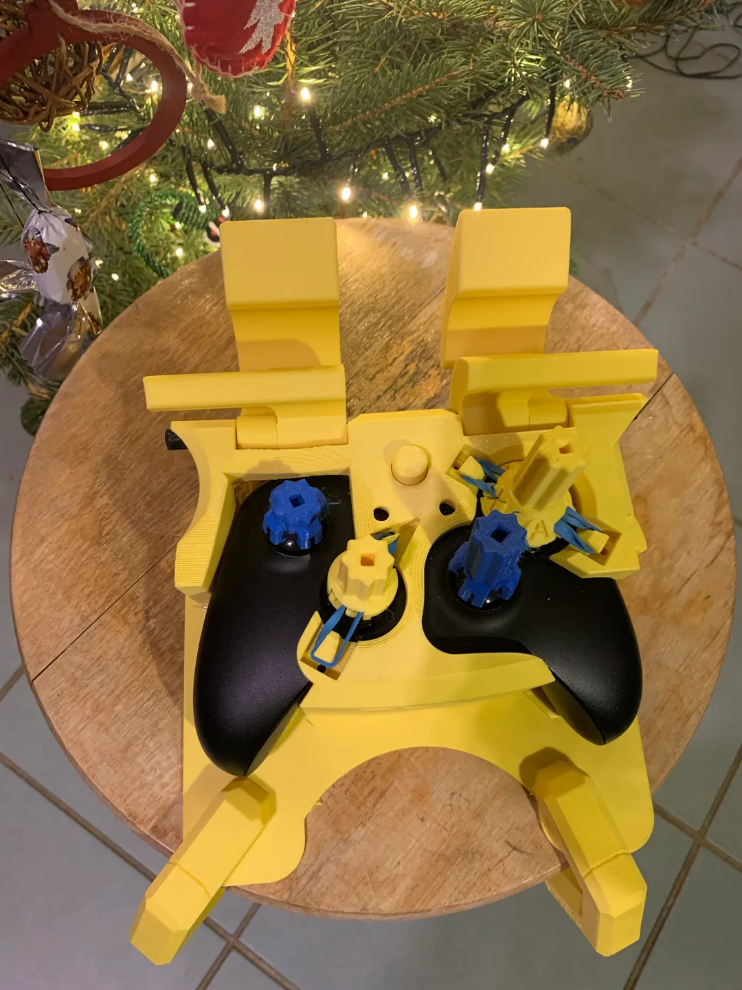
2x Rubber Bands, for holding the joysticks in place
3x 15-50mm M3 screws
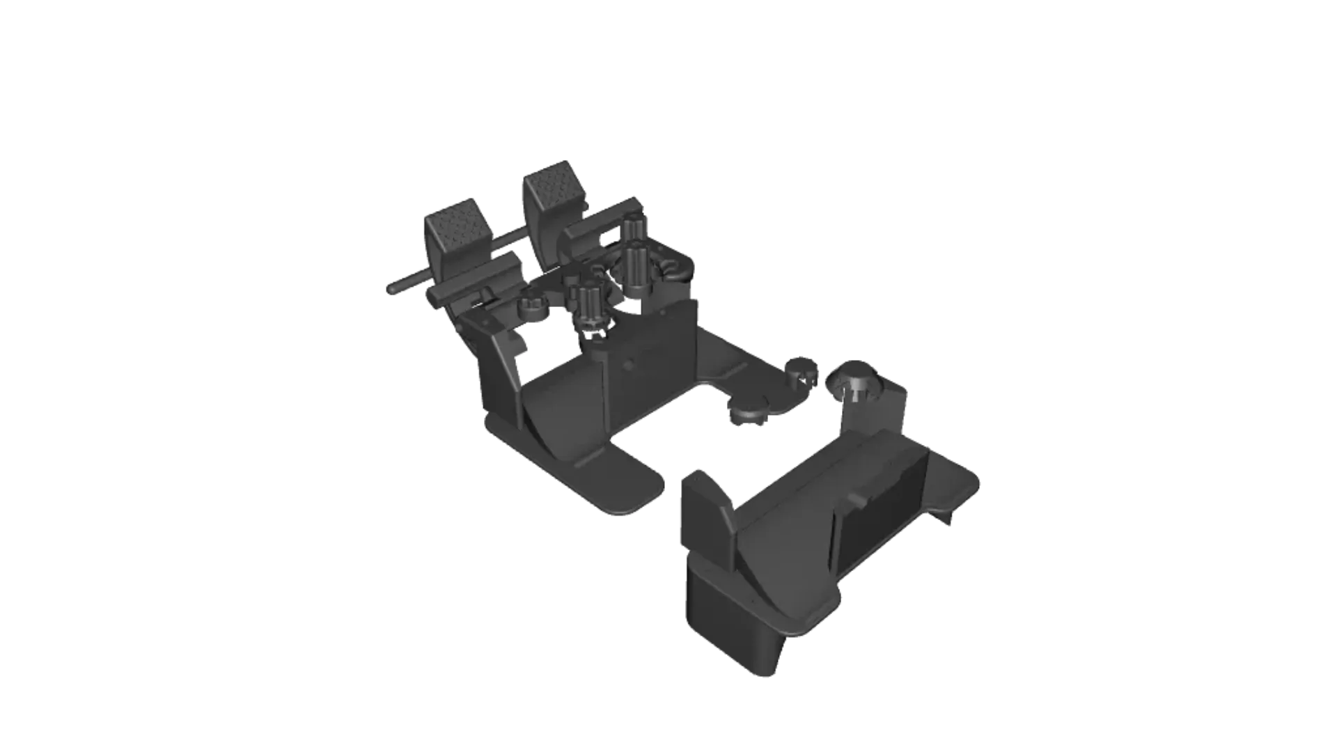
Assembly:
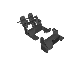
There are two main parts to the build:
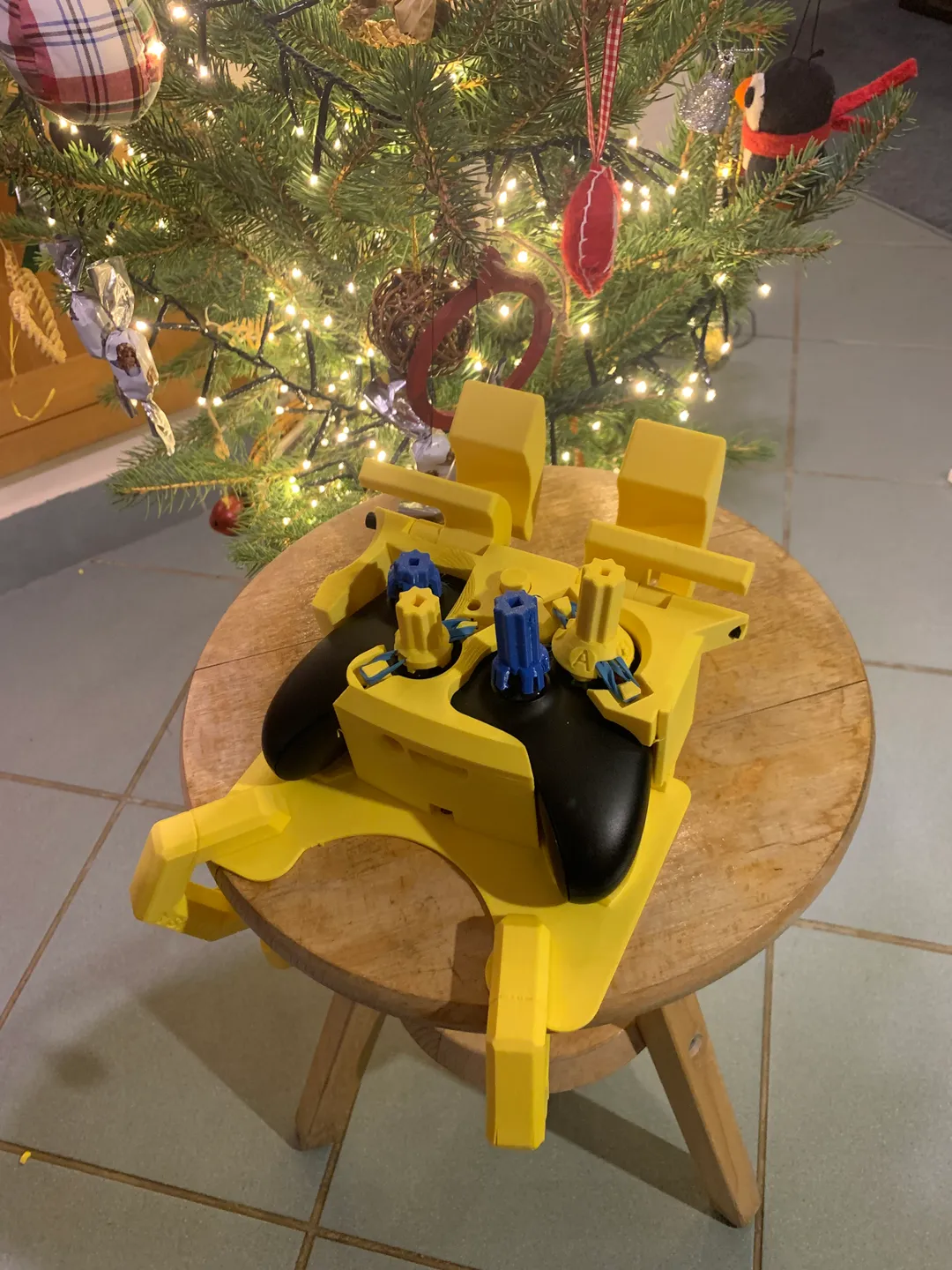
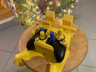
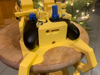
- "Main Top Plate.3mf" goes onto the top of the controller.
- "Main Bottom Plate.3mf" goes under the controller and can get clamped to a table (I used Prusa's PETG clamp: https://www.prusaprinters.org/prints/758-petg-prusament-clamp). There is also a more compact version of the bottom plate that can be screwed to a table.
The controller itself goes in-between these two parts.
PRO TIP: If anything feels loose, Blu-Tack can really help adjust for tolerances
Step 1)
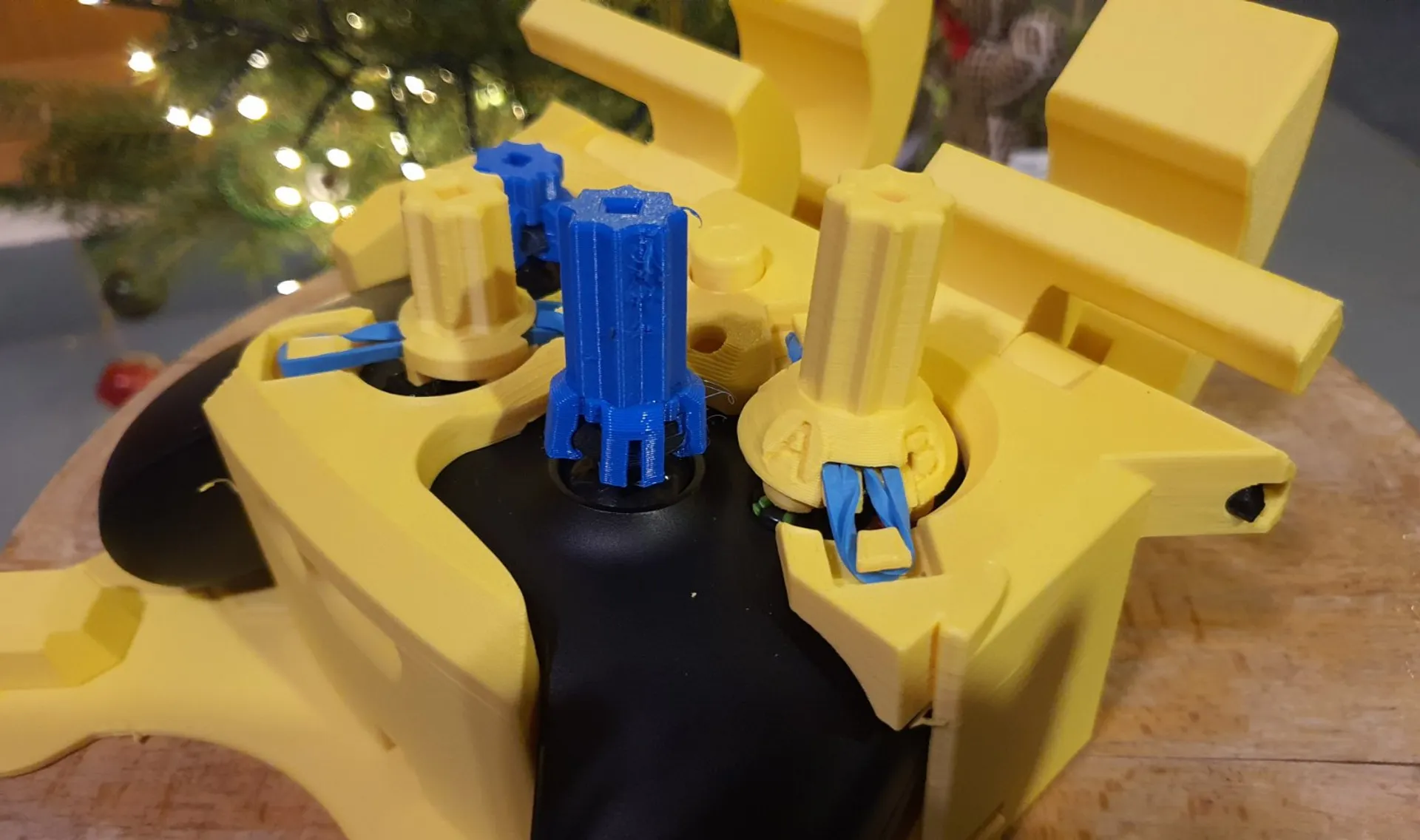
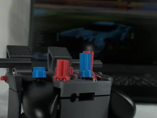
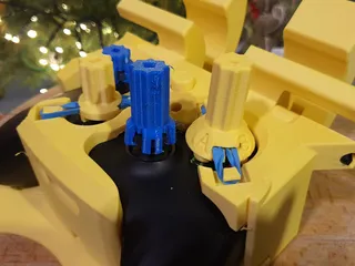
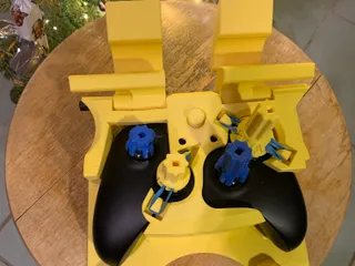
Fold rubber bands in half, then put their loops into their respective slots on the “Main Top Plate.3mf”. The four pegs that the rubber bands go onto are adjacent to the D pad's slot and the button's slot. Then put the ”Button Joystick Top.3mf" and "Button Joystick.3mf" together, with the rubber band in-between the two parts. Do the same with “D pad Joystick Top.3mf" and "D pad Joystick Bottom.3mf”.
Step 2)
Press the “Joystick Extender”-s onto the respective joysticks.
Step 3)
To keep the On/Off button's functionality, slide the “Xbox Logo Presser.3mf” and the "Small Button Pusher.3mf"-s through the bottom of the “Main Top Plate.3mf”. There are little rings on the ends of the rods so that they don't fall out once the "Main Top Plate.3mf” is on the controller.
Step 4)
Put the assembled "Main Top Plate.3mf” onto the "Main Bottom Plate.3mf" with the controller in-between, and use M3 screws to screw them together (the holes can be found on the top of the "Main Top Plate.3mf").
Step 5)
Start sliding the long rod through the hole in front of the controller going through the extended trigger modifications. If pushing the rod from left to right, their order should be: Outer Trigger Left.3mf, Inner Trigger Left.3mf, Inner Trigger Right.3mf, then Outer Trigger Right.3mf
Here is my video of the assembly:
Note: the newest version has the screws going in through the same places in the top.
Tags
Model origin
The author hasn't provided the model origin yet.