Raspberry Pi Touch Screen enclosure
Description
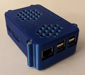
PDFThis project is for a 3D printed enclosure for the standard Raspberry Pi Touch Screen and uses a Raspberry Pi 5 with the Bookworm OS to run software that is both a photo display system as well as a ‘dashboard’ for collecting and showing a range of home automation and local sensor data.
The enclosure uses a build/print approach first developed for this previous design and which is used again in several other designs. The enclosure's main walls are bolted together with 16mm long M3 pan head screws engaging with M3 nuts that are ‘pulled’ into the hex openings on the corner blocks. 6mm M2 self tap flanged pan head screws are used to attach the two end walls and for the additional fixing points in the middle of the front and back walls. 4mm M3 pan head screws are used to attach the USB-C connector ‘panel’ to the inside of the TS_top03 component and 4mm + 6mm M3 pan head screws are used to attach the ethernet ‘panel’ and ‘strap’ to the TS_top03 component.
More detail on the usage context is available from this link.
All the components use 1.75mm PLA and a layer height of 0.15mm with print details for each component produced on an i3 Mk3 shown in the table below - but it should be noted that the front, back and top designations in the file names are descriptions for the assembly positioned screen face down.
| component file name/description | brim (mm) | support | filament length (m) | print time (i3 Mk3) |
| TS_display-front+text01_rotx180.stl: main front holder for the Raspberry Pi Touch Screen | 10 mm 0.2 mm gap | none | 17.76 | 4h 40m |
| TS_base01.stl: back plate attached to the main front holder to which the enclosure walls are attached | 10 mm 0.2 mm gap | none | 8.88 | 2h 53m |
| TS_front_wall01_rotx90.stl: front wall of the enclosure | 10 mm 0.2 mm gap | build plate only - 0.2 detachable | 8.62 | 2h 36m |
| TS_back_wall02_rotx90.stl: back wall of the enclosure | 10 mm 0.2 mm gap | build plate only - 0.2 detachable | 8.59 | 2h 55m |
| TS_left_end_wall01_roty90.stl: left end wall of the enclosure | 10 mm 0.2 mm gap | build plate only - 0.2 detachable | 3.98 | 1h 1m |
| TS_right_end_wall01_roty90.stl: left end wall of the enclosure | 10 mm 0.2 mm gap | build plate only - 0.2 detachable | 3.98 | 1h 1m |
| TS_top03.stl: top wall of the enclosure with openings to attach the ethernet and USB-C power connector 'panels' | 10 mm 0.2 mm gap | build plate only - 0.2 detachable | 12.42 | 3h 46m |
| TS_eth-adapt_panel01_rotx90.stl: ethernet connector ‘panel’ that is attached in an opening in the TS_top03 component | none | build plate only - 0.2 detachable | 0.9 | 20m |
| TS_eth-strap02_roty90.stl: small ‘strap’ used to secure the two-way ethernet adaptor into the ethernet connector ‘panel’ where the combined assembly is attached in an opening in the TS_top03 component | 3 mm 0.2 mm gap | none | 0.42 | 17m |
| TS_USB-C_panel01_rotx90.stl: small enclosure USB end wall | 3 mm 0.2 mm gap | build plate only - 0.2 detachable | 0.58 | 18m |
Tags
Model origin
The author marked this model as their own original creation.


