External MMU Mounting System (EMMS) for Original Prusa Enclosure (OPE) and Ultimulti

Description
PDFFinal release after more than 6 months of developing and testing!
After a several month long beta process and countless improvements (especially of the auto-rewind mechanism) the complete EMMS works 100% reliable for month now. It took some time but finally I am exited to release the FINAL VERSION now!!

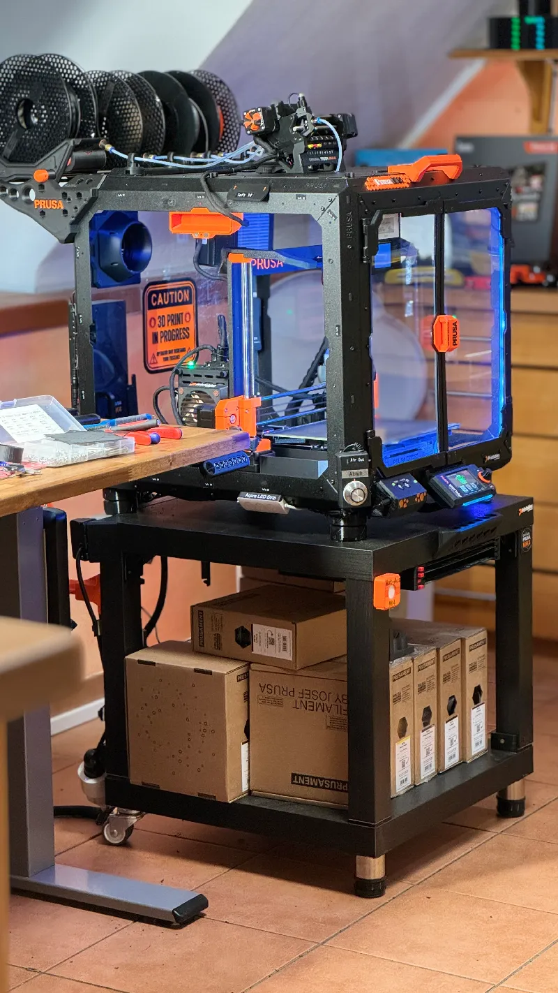
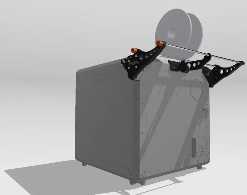
Aim of the project is to have the complete MMU system at hand outside of the enclosure (on the top) for better access to all MMU components (which often require manual adjustment). Positive side effect: More free space inside the enclosure!
The MMU system I prefer is the Ultimulti MMU mod by @David because it works best for me and is most reliable. The EMMS ist based on this MMU mod but works with stock MMU as well but will need a custom stand (will be developed and published here later on)
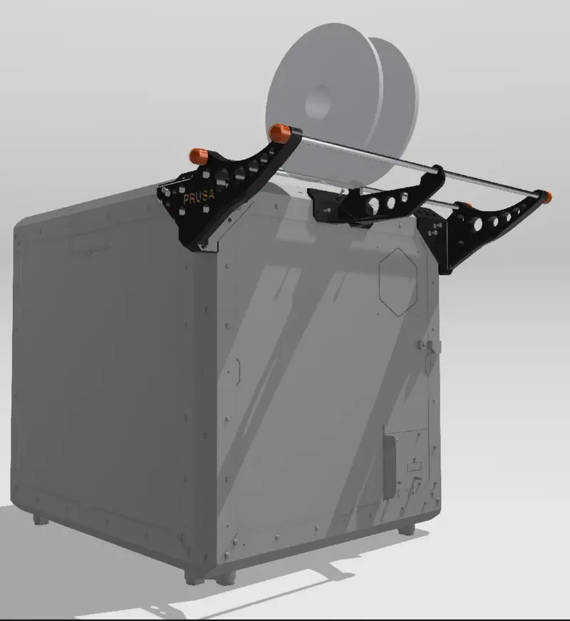
Up to five spools can be mounted this way (without the auto rewind carriers you can even place 6 spools directly on the smooth steel rods).
After a lot of modeling, testing and producing a lot of PFTE-junk to be recycled by the German startup “Recycling Fabrik” I finally use a modified version of auto rewind spool holder for RepRack by @Jerrari. To fit to my OPE spool mounting system I had to modify his system. Only the Spring loaded cylinders were kept from @Jerraris wonderful design.
There are some things you have to consider before beginning to build the EMMS:
- you have to extend the MMU cable. This requires some basic crimping and soldering skills. The extended cable should not be longer than 1,5m (I experienced problems with longer cables. Dont know why - ask Josef Prusa :-) )
- the MMU to Extruder PTFE tube is longer than in the standard on-printer-installation. That means longer loops when retracting filament for changing material. So this requires a “bigger” buffer. That was one of the problems to solve. But I created a solution that works reliably in the end.
- you need an 8 pin connector for the MMU extension cable I used 8-Pin DT Deutsch plugs. I recommend buying two spare MMU MK4 cables from PRUSA and modify them and keep the original cable as spare. Basic soldering and crimping skills will help.
- You will have to drill a 4-6mm hole in the Top/Lid of the enclosure to pass the PTFE tube to the Nextruder.
- You need some TIME and patience. Printing all that stuff takes quite some time. This is a really huge project! And you will have to invest some money in filament and magnets !
BUT ITS TOTALLY WORTH IT !
I printed the bigger parts on a PRUSA MK4(S) with 0,4mm nozzle and the smaller parts on a PRUSA MK3.5 with 0,25mm nozzle. So some gcode files refer to MK4(S) and others to MK3.5. I thought most of you will use the *.stl or *.3mf files (like I do) and the gcode files are less important.
If you like better, I can exchange the MK3.5 files by MK4(S) files so that all gcodes refer to the same printer model.

You can find all model files here or in the link to the respective part with detailed descriptions
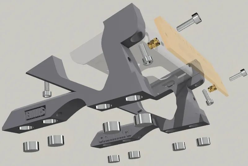
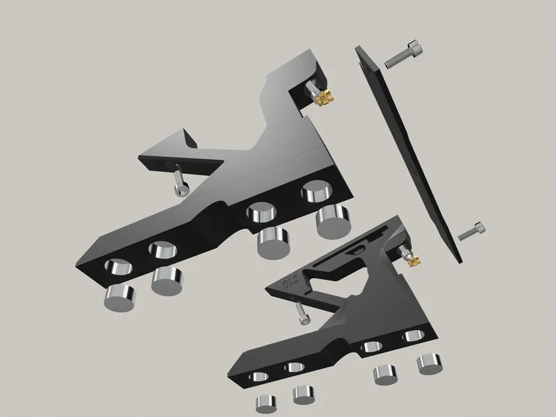
Part 1 Mount system for UltiMulti MMU on top of the lid of the OPE with short legs for low profile. It attaches magnetically to the lid. A Version with legs for the standard Prusa MMU will follow soon.
A cable extension is necessary. It works with a “deutsch DT 12x connector” that is attached magnetically to the handles at the side of the OPE

Part 2 The MMU cable extension with a mount inside the OPE. The cable extension requires basic crimping or soldering skills. Unfortunately PRUSA does not provide a longer MMU cable.
Part 3 External filament carrier - spool mount - for Original Prusa enclosure.
You may run the filament spools directly on the smooth rods. But then you need another buffer system (choose what you prefer).
The EMMS uses an autorewind spool carrier system with cages. You can put the spools onto of the spool carriers without inserting an axle or mounting anything to the spools! Does not matter of cardboard or plastic spools no matter what the manufacturer is. Up to 1kg spools ares supported.
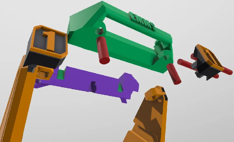
Part 4 Spool Carriers that mount on the smooth rods and can be shifted freely from left to right. I redesigned the auto rewind spool holders by @Jerrari and kept only the spring loaded cylinders with internal clutch of his system. There are some things to take care of to get this really great system to work (Further advice can be found in my detailed comments to makes of the EMMS). @Jerraris system is based on the groundbreaking work of @Vincent Groenhuis who developed surely one of the best auto rewind spoolholder systems. I don't use the system by @Vincent Groenhuis in this design, because I didn't want having to mount special support systems (axis) to every spool again and again. I still use the original autorewind spoolholders with my other PRUSA 3.5/MMU3. Before using a spool, I have to install the mechanism to each spool I want to use and have to remove it when finished. This works great for years now, but I wanted to try something simpler and quicker. Idea: Just put the spool on a carrier and it will rewind automatically when needed. Getting this to work was the most difficult part of the whole EMMS design.
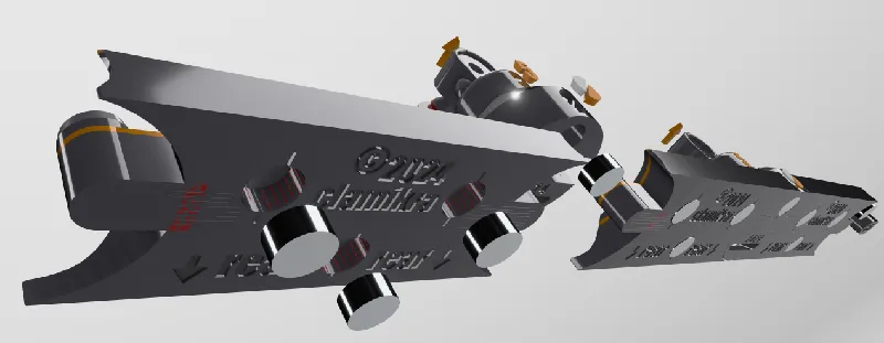
Part 5 A unique newly designed Filament guide for the spool carrier with almost no friction. Therefore I used the OUTER SURFACE of PTFE tubes to minimize friction (which is important for the seamless function the integrated auto rewind spool system).
Part 6 A Cage to keep the filament on spool if retraction is incomplete. The PETG coils are not very reliable and very in strength. If they don't retract the filament completely the cage will keep the loops near the spool so that when loading filament again it does not entangle around the spool. The cage is attached magnetically to the carrier and can be removed easily and without tools. The spools can be loaded and unloaded from the front without removing the cage.

Part 7 PTFE tube guide that has a funnel to make inserting the filament easier and sits on top of the lid of the Original Prusa enclosure held by 5x10mm magnets. The funnels are a snap-fit part into the base and need no glue.
Materials you will need:
For all this you will need some magnets. Be careful to purchase the really strong N52 class magnets. There are other cheap not very strong magnets of the same size available that I don't recommend.
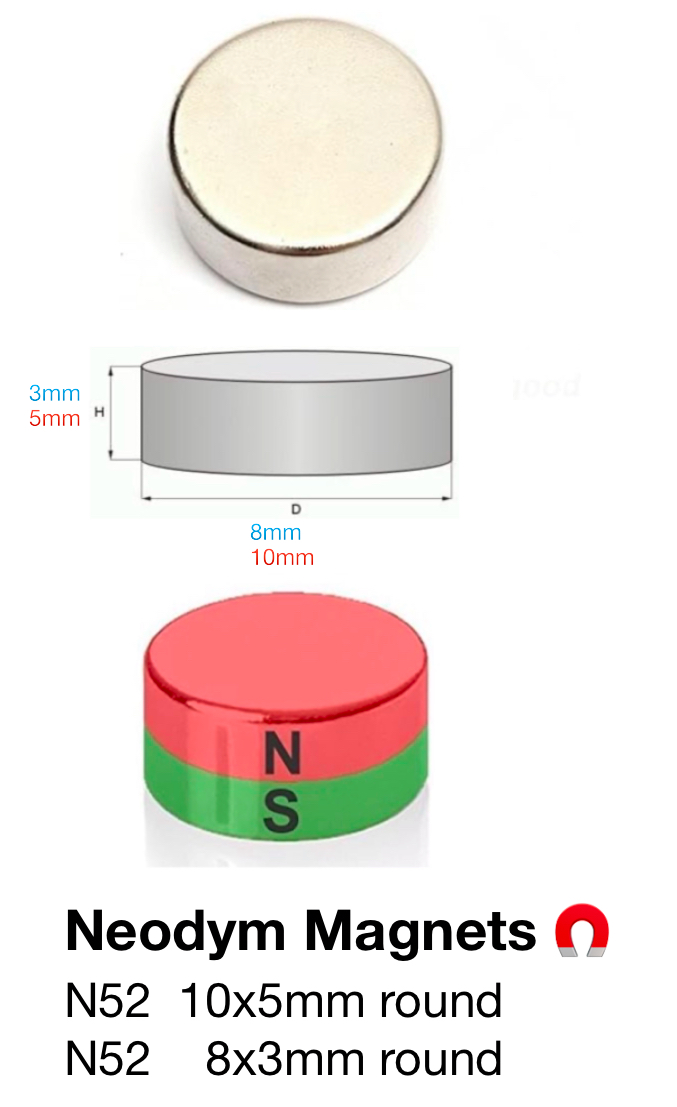
Number of magnets you will need:
10x5mm N52 magnets (Amazon link)
MMU Mount: 6-8
Guide: 17
Total: 25
8x3mm N52 magnets (Amazon link)
Cages 25
Carriers 25
Total 50
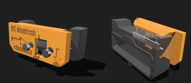
DT deutsch Mount:
10x5mm 2
10x40x1mm 4 (or 80x10x2mm in one piece)
A set of M3 hex screws / nuts and some M3 heat set threads (CNC kitchen provides the best) are necessary.
I printed everything with Prusament PETG filament.
- Matte Black
- Prusa Orange
- Urban Gray

MMU Mount System ← Link to detailed description
Materials needed
- 1 DT deutsch 12x connector male and female (Amazon Link) for cable extension
- 8x 10x5mm N52 magnets for each guide (Amazon link)
- some M3 screws
- 2x M3 heat set inserts
- The original MMU3 Label plate (when you don't have it anymore you can print it by yourself with this models
- MMU3 model plate (STEP File)
- alternative MMU3 model plate
and I guess there are lots more

After assembly you have to find the correct place onto of the OPE for the MMU. The best place ist exactly over the filament inlet of the extruder. Drill a small hole of about 5-6mm and clean the metal edges to become less sharp (be careful that no metal debris falls onto the printer).
Remove the printer out of the enclosure when drilling or use at least a blanket if removing printer is not possible. Be careful when removing the blanket not to loose any metal partikels. I inserted a small rubber ring I found in a drawer into the hole to protect the edges.
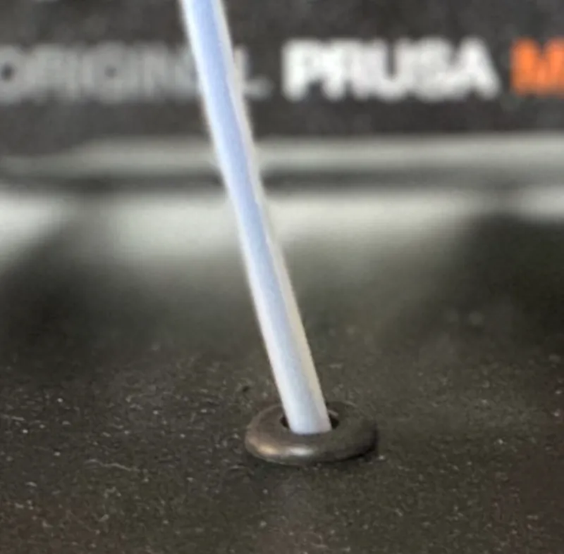
You may use this or this as grommet for the hole. You will have to downsize these models a bit.

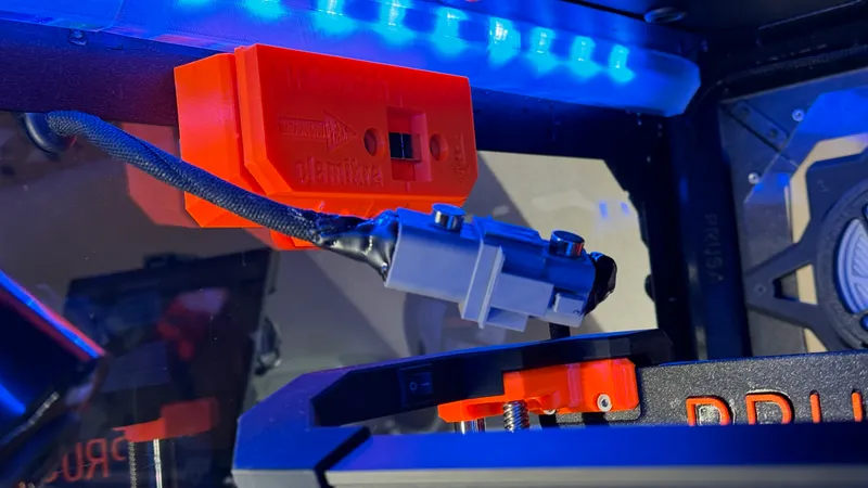
The cable for the MMU has to be extended for positioning it onto of the OPE. I put an 8-pin connector in the middle of the by approximately 50cm extended cable which is inside the OPE and is not visible from outside.
I used a DT Deutsch connector but you may use any other 8 pin plug. I am convinced there are smaller connectors for this but I wanted a robust and easy to assemble connector. The DT connectors are even waterproof.
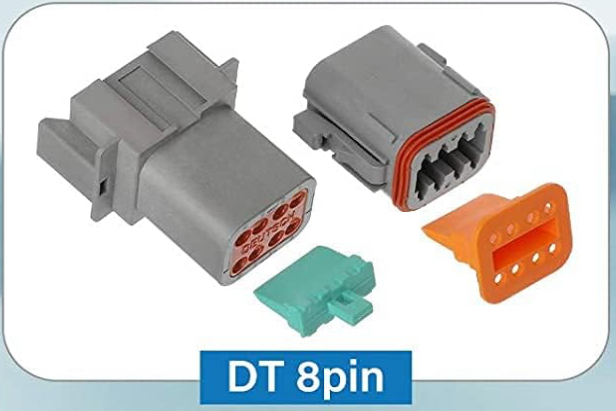
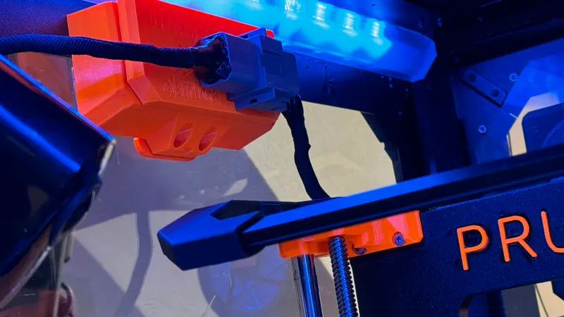
The DT Deutsch connectors with two 10x5mm N53 Magnets and the corresponding magnetic mount are set on the backside of the left OPE handle and match the contour of the handle.
There are DT sets on Amazon, that are much cheaper than buying a single pair. I bought a set for 14,-€ on Amazon. The Quality of these were absolutely ok for this project.
The DT Connector is held in place with a magnetic mount at the inner side of the Prusa handle. I extended the cable to be about 50cm longer. I had a test version that was even longer, but with about 1,5m cable the MMU didn't respond reliable (strangely).
Here are some detailed instructions how to expand the MMU cable:
* First make your self familiar with the DT deutsch connectors assembly. There are some good videos on YouTube ( https://youtu.be/_EixzYfBS50?si=o9L61I3H98bDhxGD)
* cut the original mmu cable in two parts by ⅓ (MMU side) and ⅔ (x-buddy side)
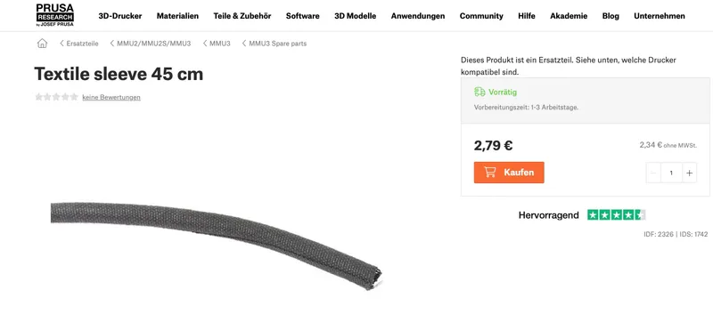
* the longer part goes directly from the x-Buddy to the female DT connector. I put some 45cm Prusa MMU textile sleeve around it after connecting the cable with the DT plug. https://www.prusa3d.com/de/produkt/textile-sleeve-45-cm/ You will need two of them.
* the shorter part goes to the mmu and is extended about 50cm by soldering each wire to a corresponding extension wire and insulate each of them after having soldered with small heat shrink tubing. The other end of the extension cable is crimped wire by wire to the male DT connectors (you can use the imprinted numbers on the DT connectors as a help or lay them near to each other in the way they will be plugged together later.
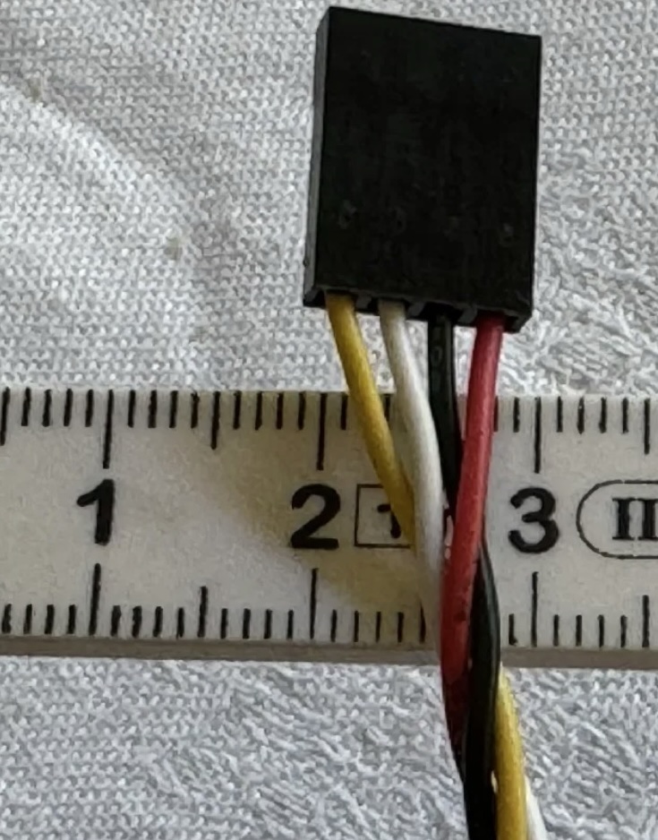
* I used some ordinary molex computer cable I had left over and coded each wire with a sharpy pen (edding marker). Cable see foto below.
* as above put some self closing textile (Prusa-) sleeve around the new cable after connecting the DT plug
* after soldering and assembly I tested each contact with a voltage (ohm) meter for correct current transition. Check that each pin of the one side matches the pin of the other side of the whole extended cable.
* After successfully testing each part of both cables parts for that there are no mixed up connections/cables I connected the DT plugs and tested a final round. In doubt test one more time to be absolutely sure, that the x-Buddy plug pins match exactly the MMU-Plug pins.
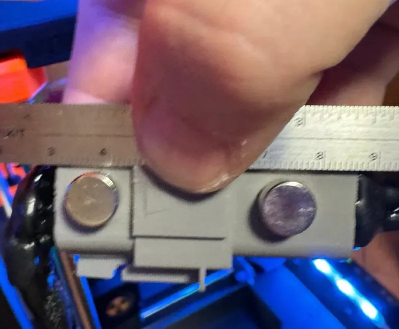
* After I proved the MMU is working with the newly expanded cable I glued two 5x10mm round N52 magnets to the ST plug in such a way, that they match the holes of the printed mount for the inner side of the OPE handle.
The easiest way to do this, is setting the magents in the mount already loaded with the other matching magnets. When the round magnets sit in their corresponding cutout of the mount give a drop of super glue on the visible side and set the DT plug in the mount and press it some seconds against the round magnets with the glue. This way the plug will fit perfectly in the handle mount.

Spool holder: ← Link to detailed description
Materials needed:
- 8 MM X 600 mm Linear Motion Rod stainles steel (600mm length has not to be trimmed), can be used as it is (Amazon link)
- some m3 grub screws
It is printed in PETG and fits the original PRUSA enclosure (OPE). You can just run the spools directly on the rods or use the “riders” spool holders provided with this mount (see the detailed Printable page). In an phase of the project I used those riders to let the spools roll with minimal friction. But you definitely will need a buffer system for them. In the beginning I developed an “Air Buffer” system that lead to entangled filament sooner or later. Over time I found a better solution with auto rewind spool holders (see below).

These Spool Carriers with Auto Rewind System are (PETG-printed) spring loaded auto rewind spool carriers with special spool holders that sit on the two 8mm smooth steel rods. The auto rewind spool holders can be moved freely along the two smooth steel rods. I used the spring loaded cylinders by @Jerrari. Five spools fit next to each other on the rods of the external mount system.

For assembly of the carrier frame you may need the following:
- 4x M3x6mm (for front and back)
- 4x M3x8mm (for the base)
- 8x M3 nuts
The auto rewind mechanism and the corresponding coils (PETG printed springs) for the cylinder and the coils you will have to download from @Jerraris auto spool rewinder page. This is an excellent page and fun to read. There you will find detailed assembling descriptions and videos about the mechanism behind the system.
FollowiIngrid are some HINTS I discovered drang the long testing procedure to get best possible working, strong autorewind cylinders. Keep in mind they were not designed for that long retraction loops the EMMS produces. So don’t blame @Jerrariss for incomplete retraction that may occur from time to time. It’s just because of the longer distance between MMU filament outlet and the Nextruder inlet when placing the MMU outside - that means farther away than in the original on frame design. That’s why the CAGES (see below) became necessary.
HINTS for best working retraction cylinders:
- print several springs, more than you may need, try them all and keep those, that rewind best. I had one carrier that wasn’t assembled to the OPE on a desk and a heavy, new filament spool as a test station to select best coil/cylinder combinations. Note that most of the retraction cylinders become better over time When used. Those that didn’t work were dismantled and parts reused. You may even find some spring break eventually. So print a lot of them, not all will work and you will need some spare coils and clutches.
- use the medium coils. The strong ones cause trouble with the MMU4 ( @Jerrariss warning is true.)
- when printing the cylinder it worked best for me when setting the seam option in prusa slicer to „random“. This prevents that a longitudinal rim builds up that may block the rotation of spool or cylinder or even the coils inside.
- the inside of the cylinders/spring covers have to be as smooth as possible. Some sanding inside helps a lot.
- the bearings should spin freely if you give them a push when holding one between two fingers. like a fidget toy. Most bearings are filled with grease that is much to sticky for this. I found the best way to make them run without resistance is, to remove one side of the thin plastic protection (be careful not to loose one of the bearing balls inside) and soak them for 24h in a small glass with isopropanol until all grease has dissolved in the alcohol. It may work either way with not opened bearings as well, but some of the covers may change color a bit When soaked in isopropanol.
When all grease is dissolved don’t relube them. The bearings literally fly now and the mechanical stress in the EMMS is so low, they will work with almost no lubrication (the tiny leftover grease that has not dissolved in the alcohol is enough). You may try with a drop of non or ultra low viskose synthetic oil If you feel better with relubricating the bearings a tiny bit.- Don’t care about the surface of the cylinders. It’s not bad if the are not to soft Or covered with soft material. If the have the untreated PETG surface (I used the prusament MATTE black). Thus the spools will slip when the coils block eventually and the filament can unspool further on. When the blocked cylinder retracts it supports the rotation of the spool anyway.

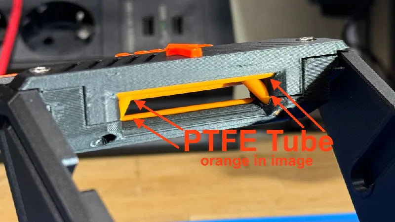
A completely new designed Filament guide with almost no friction. Therefore I used the outer SURFACE of PTFE tubes for minimizing friction (which is important for the integrated auto rewind spool system).
The PTFE tube in the picture to the right is orange so you can see it better (I had some cheap orange china ones lying around that are perfect for the job but did not work for printing at all).
The filament makes contact only with the surface of the integrated PTFE tubes. That reduces friction to a minimum.
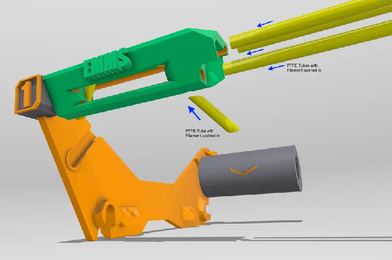
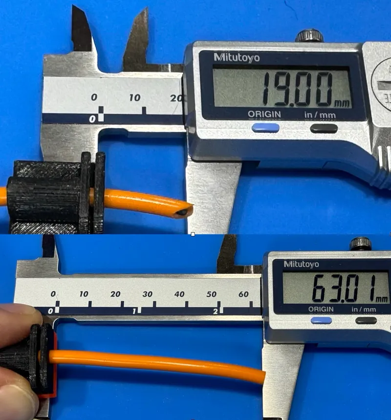
To achieve ultra low friction PTFE Tubes (see image above: yellow) are inserted into the front part from the side before installing to the carrier. 3 long ones (63mm) and two shorter ones (19mm). For the shorter ones it is best if you cut them I an oblique angle on one side first like in the picture. After inserting them from the bottom of the front part cut to the correct length directly above the surface of the printed part. When the front part is installed, the tubes are secured from falling out by the side parts (only the small ones are not, but stick well anyway because of the riffled pattern inside the short cutouts. If necessary there is glue for that. To make the PTFE tubes a bit stiffer and more straight I inserted left over Filament pieces into them before installing them.
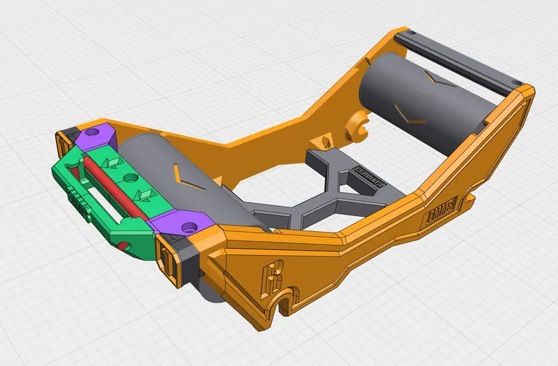
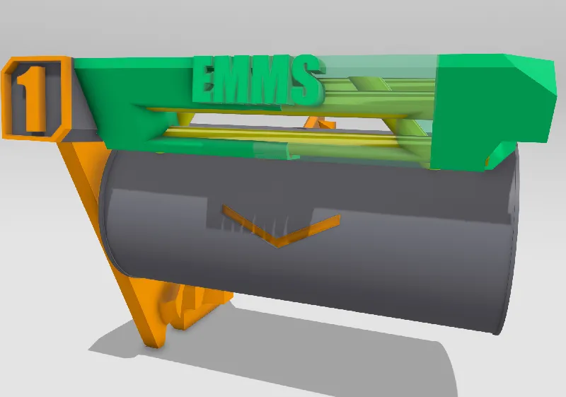
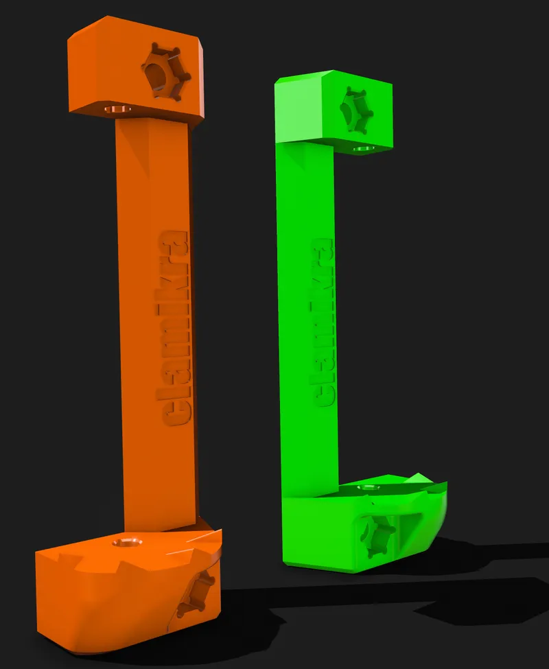
Filament Guide V9
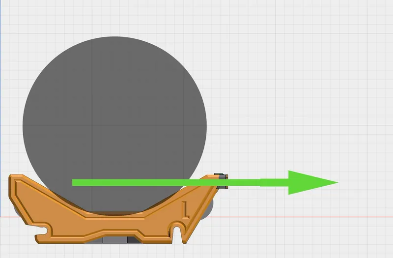
V9 is useful when you place the spool in a way on the carrier that the filament runs from the BOTTOM of the spool almost horizontal towards the MMU. It may even touch the front rewind cylinders a bit (may help!). I think this the best way as the filament runs straight almost horizontally to the MMU. From my experience this is the better way to place the spool on the auto rewind cylinders.
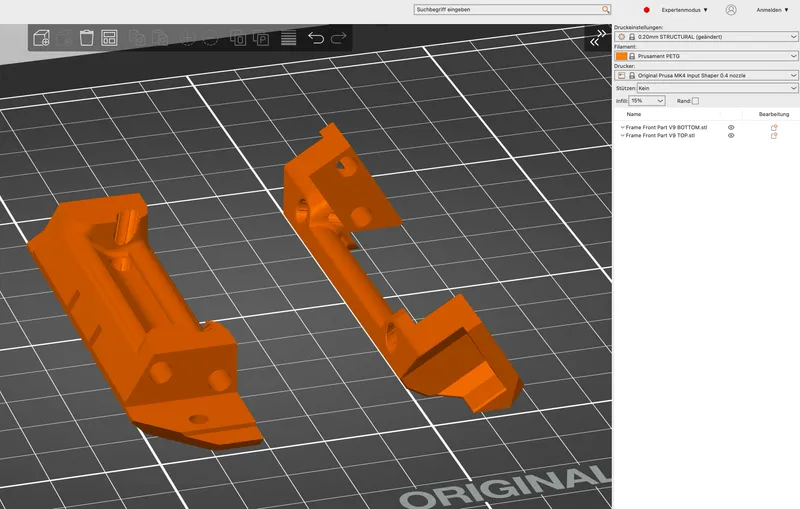
V9 prints easy without support despite its complexity. It consists of two parts that are held together with the two bolts that fix the whole part to the frame and the PTFE Filament. Mind the orientation on the printbed (see image) thus it does not need support.
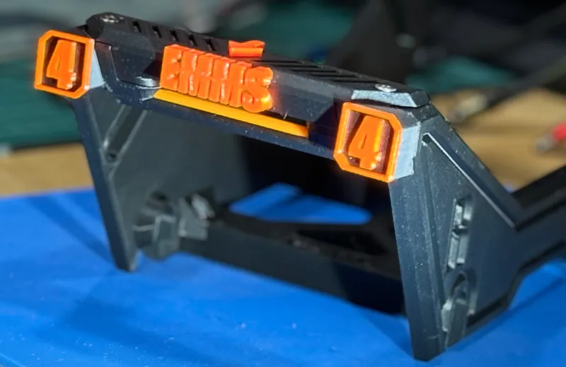
For decoration purposes the arrow and the EMMS Logo are printed in PRUSA orange and snap into place.
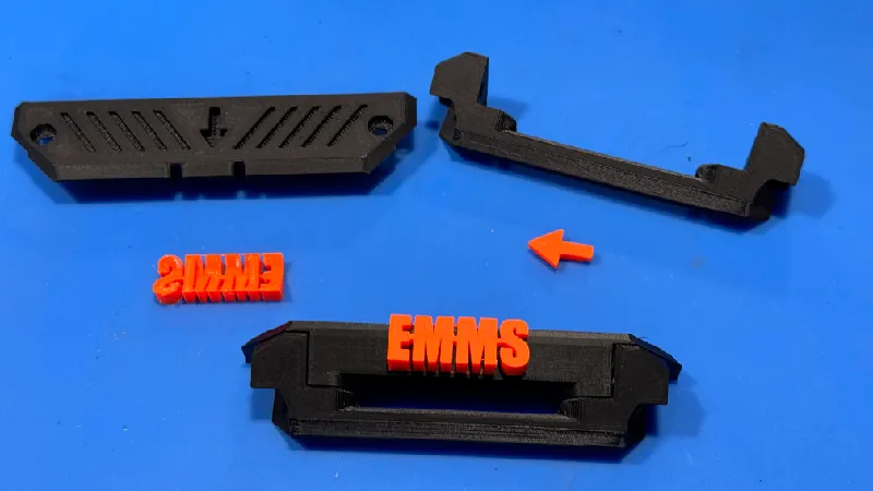
For cleaner details I printed Arrow and Logo with 0,25 Nozzle - but 0,4 will do the job aswell. You may use a little drop of super glue when assembling orange parts to secure this tiny pieces. I don't recommend to use glue to assemble Top and Bottom part, as that may make inserting the PTFE tubes more difficult.
======= Exchangeable Numbers for Marking Carriers =========
The numbers can be printed without an MMU (but if you use the EMMS you should have an MMU). Each Number is glued to the corresponding right or left Numbers Plug. Mind that there are different number plates for left and right side.

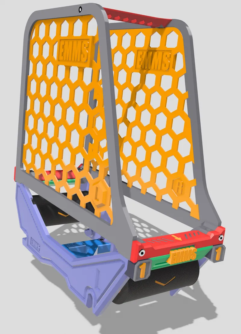
The cages attach magnetically to the spool carrier and can stay in place when loading or unloading spools. The prevent that filament entangles to the spool in case the autorewind spools do not retract the filament fully.
This made the whole system reliable and thus it does not mattering case an autorewind roller does not rewind completely or is stuck and does not move at all when retracting starts.
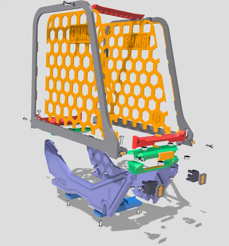
Print Frame (Black) first then glue the Mesh (ORANGE) in. To assemble the parts use M3 heat set threads (CNC kitchen provides the best) and M3 hex screws. Before assembling the parts insert the 8x3mm N52 round magents in the respective slots. Depending on the calibration of your printer no glue is required for the most cases. if the magnets sit not tight enough just use a little drop of superglue to secure them.

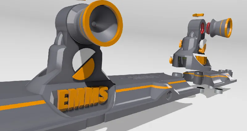
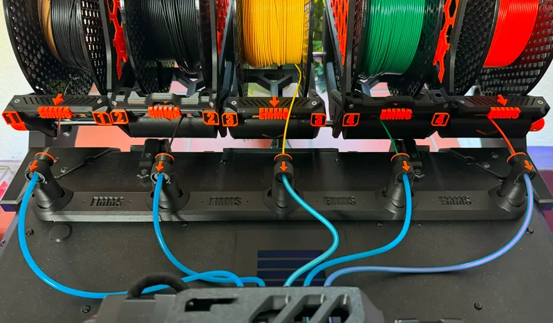
The PTFE tube guides lead the filament to the MMU unit and let you manipulate the filament by hand if adjustments are required. You will need 5 base units and 4 connectors that snap into each other like puzzle pieces. The first and last base take the end plugs to cover the holes where no connectors are added (left and right are not the same !! Double check before inserting.)
Most of the colored parts are inlays that are printed separately (best with 0,25mm nozzle) and may need a drop of superglue (not to much!!). This reduces printing time drastically. If printing those big parts with MMU would take for ever and produce quite a pile of purging towers just to throw this filament junk away (or send them to a recycling company). You can separate the parts of the guide chain by pushing a screwdriver or pin through the holes and pressing them out of the fitting holes.. The magnets can be removed the same way to be reused. That's why there are a lot of small holes on the top surface.
There should be a 10-15cm gap between spool carrier outlet and funnel of the PTFE guide. This is needed for manipulation of the filament with hands when necessary. Note, that the PTFE tube of spool no. 3 is intentionally not straight. If it was straight, the force of the retraction mechanism pulls the filament out of the MMU when not loaded into nozzle. The tiny amount of friction is necessary in line 3.

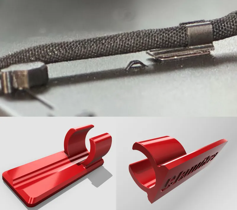
I made a nice little cable guide for the extended MMU cable that attaches magnetically to the Prusa Enclosure's top. It uses adhesive magnets with 10x30x1mm like these from Amazon. It lets the cable stay where it is meant to be.
To make this part elastic enough and to avoid breaking it into parts when inserting the cable you have to print it in an upright position with the ring on the printbed.
PETG Filament is recommended because some flexibility is needed.
b) New door hinges with stops that keep doors open.
Files and description will follow soon!
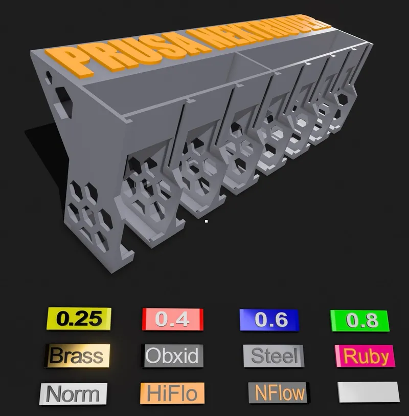
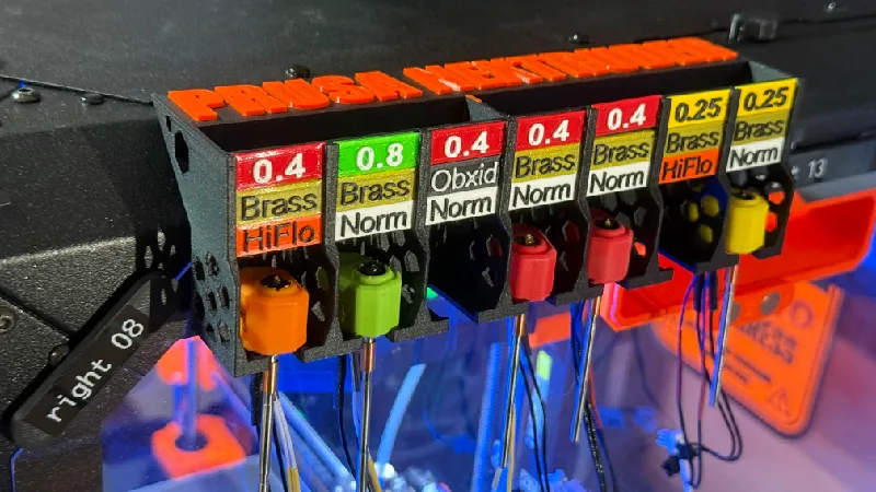
c) Magnetic Nextruder storage
with interchangeable color tags
This box gives storage for seven fully assembled Nextruders (incl. Nozzle,,Heat pill, Thermistor, Heatblock, Silicone sock). I liked the idea of @dteng and extended it to fit onto the Original Prusa Enclosure (OPE).
The Storagebox attaches magnetically to the side (or where ever you want) of the original Prusa Enclosure. The 10x5mm round N52 magnets stand off a bit intentionally so that they do not interfere with the bolt heads of the OPE (the surface of the OPE is not completely flat because of them).

=============== DISCLAIMER ===============
This is the final release of my External MMU Mount System (EMMS). But if you see ways to improve this model (or parts of it) feel free to contact me and I will try to improve this system further on.
I would be very happy if this project develops and improves over time !
Some files may be modified or exchanged in the future when improved.
You can follow all changes in the update history below.
Update History:
Update 2024_11_11:
Added Nextruder Storage Device

Update 2024_11_08:
Updated instructions.

Update 2024_11_07:
THE FINAL RELEASE FILES ARE ONLINE AND READY FOR DOWNLOAD!!!
============================================================
You will need some round magnets 10x5mm (exact number will be in
instructions published later)

Updated Files:
CARRIER:
Front- and Rear-part have to be exchanged, the sides with mesh
stay the same. The new parts have holes for 10x5mm round magnets.

New Files:
CAGE:
All parts are new and build up the cage that is attached magneti
cally to the new front and rear CARRIER parts.

FILAMENT GUIDE:
All parts are new and build up the improved guide with integrated
funnel for filament and PTFE tube. The parts snap into each other
and are attaches to the lid of the Original Prusa Enclosure by
10x5 magnets press fitted into the connectors.

FOLDERS with LEGACY PARTS have been removed.


Update 2027_07_08
- Updated Front to V9, Two part snap-in design for easier and
cleaner print. Added Logo and Arrow to front.

Update 2024_07:14
- Update Front part to V855
- Updated the RL-Numbers-Base-Plug.stl for tighter fit

Update 2024_07_13:
- Improved filament Guide V8 (new files uploaded) for horizontal
filament passway
- Updated the RL-Numbers-Base-Plug.stl for better fit (they are
not compatible with front V7 anymore. The old RL-Numbers-Base
Plug.stl moved to legacy
- More detailed Instructions for cable extension
DISCLAIMER
All links on my pages are NON affiliate Links to Amazon without any profit or cash back to me!
Please show me your printing results and send me fotos of your makes. I like to see how you use this model. If you have ideas for improvement don’t hesitate to send them to me in the comments. I will try to incorporate your suggestions and will modify the model for special needs if you ask me to do so.
And of course a like ♥ or a rating ⭐ of the design are always welcome.
happy printing,
clamikra
Tags
Model origin
The author marked this model as their own original creation.


