Customizable personalized golf ball stencil

Description
PDFThis is a customizable stencil for golf balls, indended to work with a Sharpie® Ultra Fine Point marking pen.
Using the script
The OpenSCAD files here are provided for personal use only, not for creating products to sell.
OpenSCAD version and settings
The script golfball_stencil_v4.scad requires textmetrics to be enabled in OpenSCAD. This feature exists only in OpenSCAD versions newer than 2021.01. Enable textmetrics in Edit > Preferences > Features.
The script also requires geodesic_hemisphere.scad (included).
The script is ready to use with the default Liberation Sans font.
To personalize the text, uppercase characters are recommended. There are several options for configuring the model in the OpenSCAD Customizer pane, including adjusting the finger tabs, changing the font size, and setting decorative lines.
Customizing the font
By default, the script uses the Liberation Sans font already built into OpenSCAD, although any characters with holes in them (A, B, D, O, P, Q, R) aren't going to retain the inside part of the hole, so you need to be careful with the pen. You can see in the picture that the inside triangle of the “A” fell out after printing due to not being attached to anything.L
Look for “monoline” fonts, which have uniform thickness in all strokes.
You can also use an actual stencil font to attach the holes to the rest of the structure, as shown in the last picture.
To use a custom font, the easiest way is to download the .ttf file into the same folder as the golfball_stencil_v4.scad script, and insert the line
use <font_filename.ttf>into the script near the top (substituting your font file name). Then set the fontface parameter to the name of the font. If the font is already installed in the OpenSCAD font registry, then you don't need this use command.
Print settings
- 0.4 mm nozzle
- 0.2 mm layer height (adaptive layer height should work too)
- Supports are required:
- Use 0.15 mm separation (the support should break off cleanly)
- Hex support pattern if available
- Angles shallwoer than 40° from horizontal should be supported.
How I made this
As can be seen from the file name, this is the fourth iteration of this model, which I originally made for a client in 2023. Then when I learned about textmetrics in the daily builds of OpenSCAD, I realized I could simplify the handling of proportional font spacing on a curved surface.
One of the problems I needed to solve was how to wrap text around a sphere. Initially I just treated the sphere as a cylinder, and used minkowski() to flare the text a bit so the top of the cutout was wider than the bottom. It worked but it was slow.
Eventually I decided the best way to put text on a sphere would be to scale the extrusion of each character so that each extrusion projects back to the center of the sphere, like this:
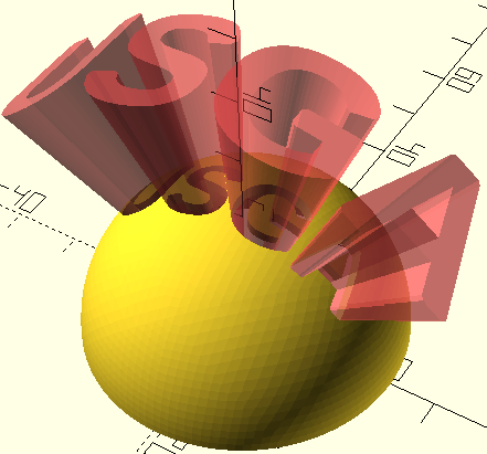
This causes all sides of the extrusion to be perpendicular to the surface of the sphere. It also has a side effect of horizontal features of each character cutout no longer being parallel to latitude coordinates, but instead fall on great circle paths. It's good enough, and it's faster and better than what I was doing before.
Tags
Model origin
The author marked this model as their own original creation.


