(Official) Nanoleaf Hexagon Flexible Mounting & Connectors

Description
PDFThis is designed for the official Nanoleaf Hexagons, it may also fit some of the DIY models but don't know for sure.

These wall mountable (with a slot for a screw on each bracket) brackets/back-plates clip onto the back of the Nanoleaf Hexagons and join together using removable connecting pieces.
The back-plates and connectors can be disconnected and re-arranged as much as you want - you no longer have to commit to a design when mounting your lights!
The brackets or back-plates clip into the back of the Nanoleaf Hexagons - the back-plates are 20mm deep and give the Nanoleaf a much cooler ‘offset’ look than when they are flush against the wall.
The brackets are connected using the small joining pieces which slot into the gaps in the back-plates.
The connecting pieces have been designed with a semi-circular ‘spring’ at each end - these should flex a little when connecting the back-plates which makes the connection more secure as it will pull the back-plates together.
How It Works
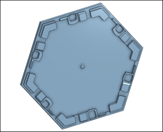
Hexagonal Back-Plates
 |  |
- The hexagonal back-plate model fits inside the inner section of the Nanoleaf - it is designed to be a tight fit and to click into place using the small indents in each corner of the Nanoleaf panel.
It will likely require a bit of force from you to push the final corners into place on each segment. But do not push down vertically on top of the Nanoleaf as you could damage it, push the corner of the back-plate towards the centre of the Nanoleaf panel so that it flexes slightly and it should click into place in the corner.
If you can't get the model to fit without excessive force then there may be printer or extrusion tolerance issues - you could try scaling the model to 98-99%.
- The 'button' on the back of the Nanoleaf can be clicked into place in the centre of the back-plate. This will help further secure the Nanoleaf to the model.
The hole will likely be a bit too tight when it comes off the printer but slowly widen the hole using a deburring tool or knife until the Nanoleaf can click on and off with approx. the same force as the Nanoleaf's official mount.
(The arms of the model are flexible enough to be able to adjust the centre hole and test the attachment without having to fully fit the back-plate each time.)
- Before final attachment of the back-plate, place two of the connecting pieces in each of the edges which you plan to connect to another panel.
Use the connectors named connector-square.stl - these go in the ‘square’ holes beside the Nanoleaf panel.
See below for full description.
Connecting Arms
- The connecting arms are used to join together panels. They join an edge of a back-plate to the edge of an adjacent back-plate.
- The connecting pieces have semi-circular ‘springs’ at the ends. These arcs are designed to flex a little when joining panels together so that they can gently pull the panels together and ensure that there is minimal risk of a connection becoming loose.
connector-square.stl
Before securing the back-plate to the panels, place the connector-square pieces in the square holes at the edge of the back-plate.
Orient the connector so that the non-flat side is against the panel. It will fit into the Nanoleaf panel's topology. One connector on each edge is rotated 180° from the other connector.
 |  |
connector-triangle.stl
Once two adjacent back-plates are attached, electrically connect the panels by snapping the small Nanoleaf circuit board piece into place.
Then use the connector-triangle.stl piece to connect the triangular cutouts of the back-plates together.
The back-plates are well connected even without this piece but it adds some rigidity to the connection and forces the panels into a flat plane.
 |  |
Number Of Pieces
If using the standard set of 9 Nanoleaf panels, you'll need a backplate per panel and at least eight sets of connecting pieces, i.e.
- 9 x back-plate.stl
- 16 x connector-square.stl
- 8 x connector-triangle.stl
But you may need more connectors depending on how you have laid out your panels and how many adjacent edges you have.
Additional LEDs
The 20mm height of the back-plates makes the Nanoleaf Hexagons look much better when wall-mounted (in my opinion) as it gives them some depth and makes them more interesting.
But the intention was also to allow space to stick an LED strip on the edges of the panels to allow some additional backlighting or glow to come from under the Nanoleafs.
(This would obviously make re-configuring the Nanoleaf shape more difficult).
I haven't gotten round to doing this yet myself but it's in the pipeline and I'll update the images here once I've done it. I will likely use some WLED controlled LEDs for this and control the panels and WLED from Home Assistant so that they can be operated together (e.g. when the Nanoleaf is turned on, the LED strip will turn on).
Reference Nanoleaf Model
I spent quite a bit of time modelling the Nanoleaf panel itself so that I could build the back-plates etc to match the proper panel dimensions.
I have included the Nanoleaf panel model in this project too, just in case anyone wants it to use for reference for any remixes or other designs.
Print Settings
The models should be printed with the 'flat' surfaces on the build plate. They should all be orientated correctly already.
I have printed these using various wall thicknesses, line widths, and infill settings and they have printed great each time but most of mine were printed using:
- Outer Wall First - if your slicer has this setting then enable it as it will help ensure dimensions are accurate (my first prints were without this setting and they did fit but not as well as when this was enabled).
In OrcaSlicer, this can be found at Quality → Walls & Surfaces → Walls Printing Order, set to Inner/Outer/Inner
In Cura this can be found at Walls → Wall Ordering, set to Outside to Inside
In PrusaSlicer this can be found in Print Settings → Layers & Perimeters → Advanced → External Perimeters First. - 0.4mm nozzle (switched to 0.6mm for 5 of 9 prints and worked great with the same settings)
- 0.2mm layer height (also successfully printed some with 0.3mm + adaptive layer height in OrcaSlicer to save time)
- 3 walls (also tried 2 walls and it worked fine)
- 3 top and 3 bottom layers (2 also worked well)
- 10% infill
- No support
You may need support if your printer has difficulty with overhangs - all overhangs are above 45° which most printers should be fine with.
Your own preferred filament and printer speed/acceleration settings will probably be fine.
- I used PLA in my initial testing but I prefer PETG for final prints (just personal preference for how it looks and feels). I used white Sunlu PETG.
- My printer is a Sovol SV06, and I printed at 200 mm/s (also successful prints at 60mm/s and 100mm/s), and acceleration was 1500mm/s² (also successful prints at 1000mm/s² and 2000mm/s²).
Tags
Model origin
The author marked this model as their own original creation.


