FatBurner – Ender 3 V3 KE Dual 5015 Fan Cooling System


Description
PDFUpdates
31 may 2024. Fixed the issue with the wall thickness of the Ducts.
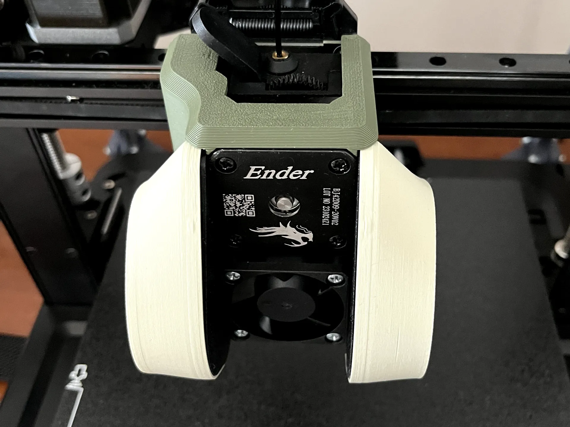
FatBurner
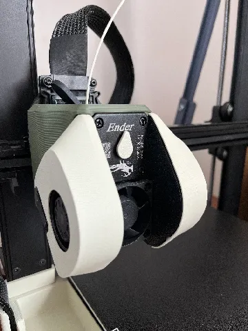
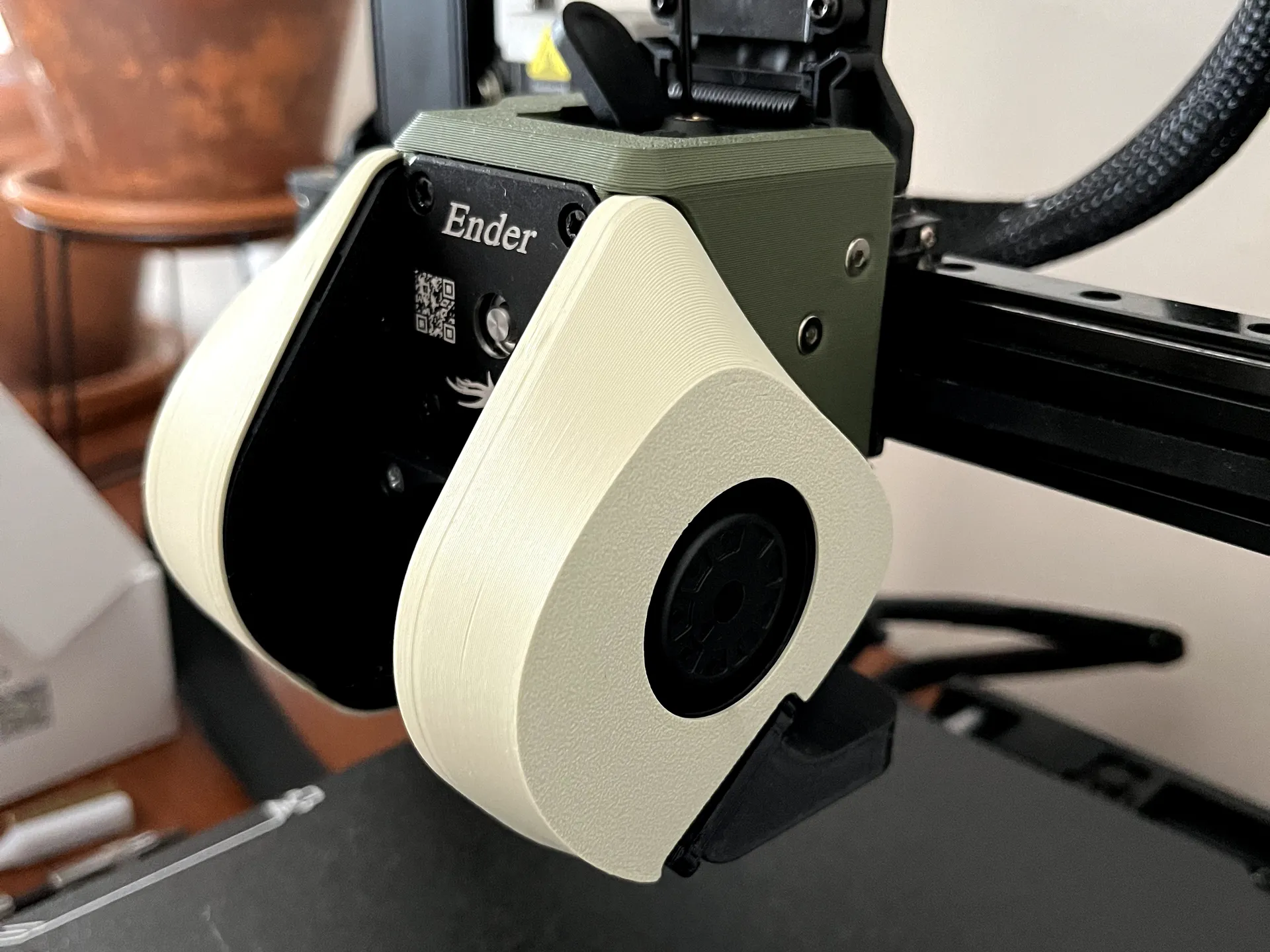
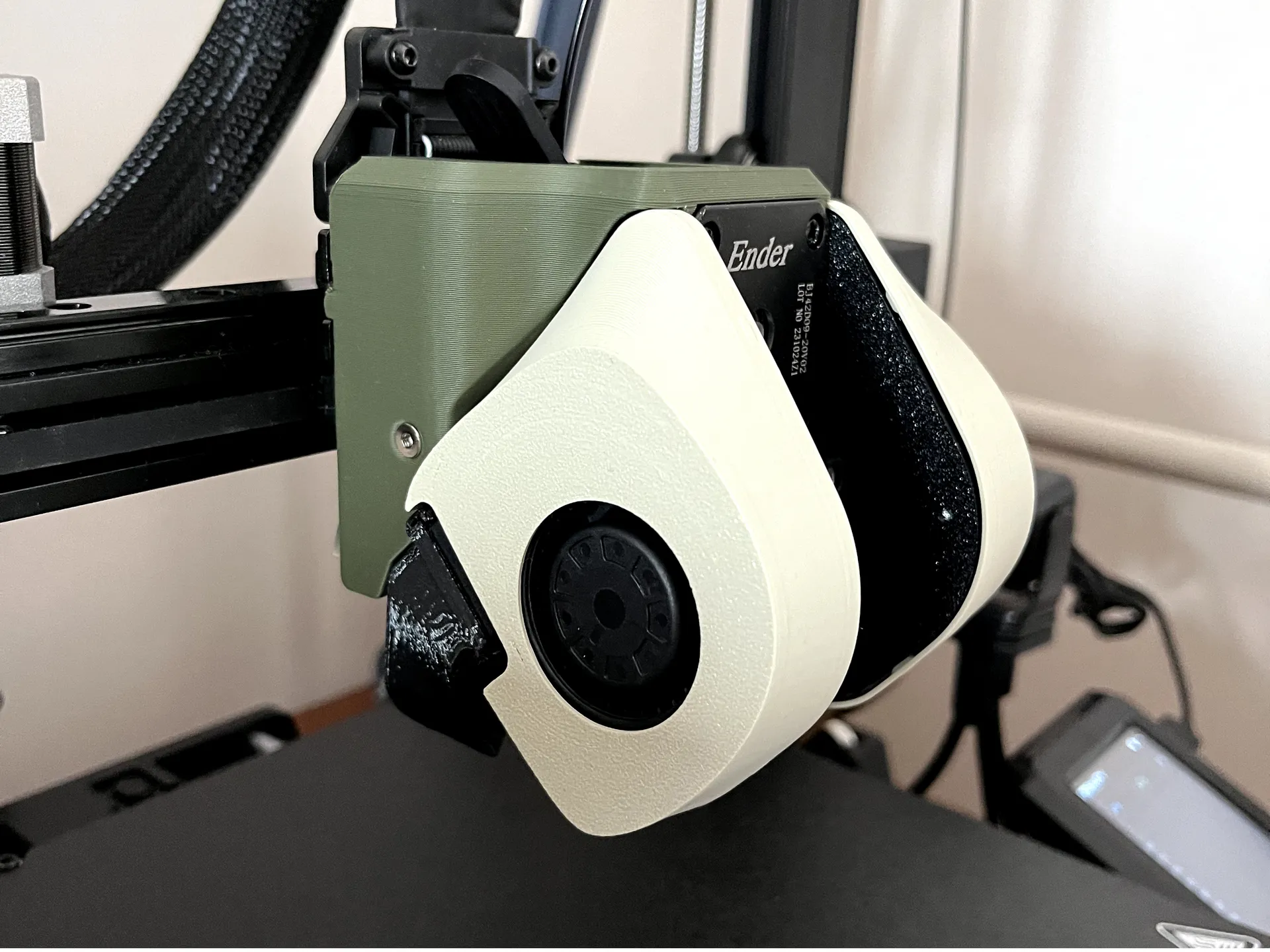
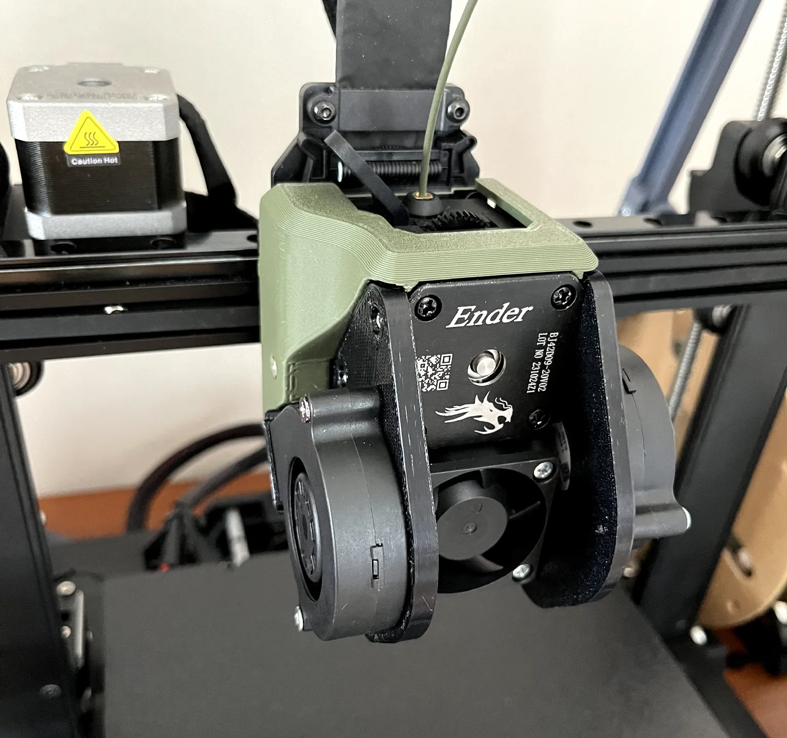
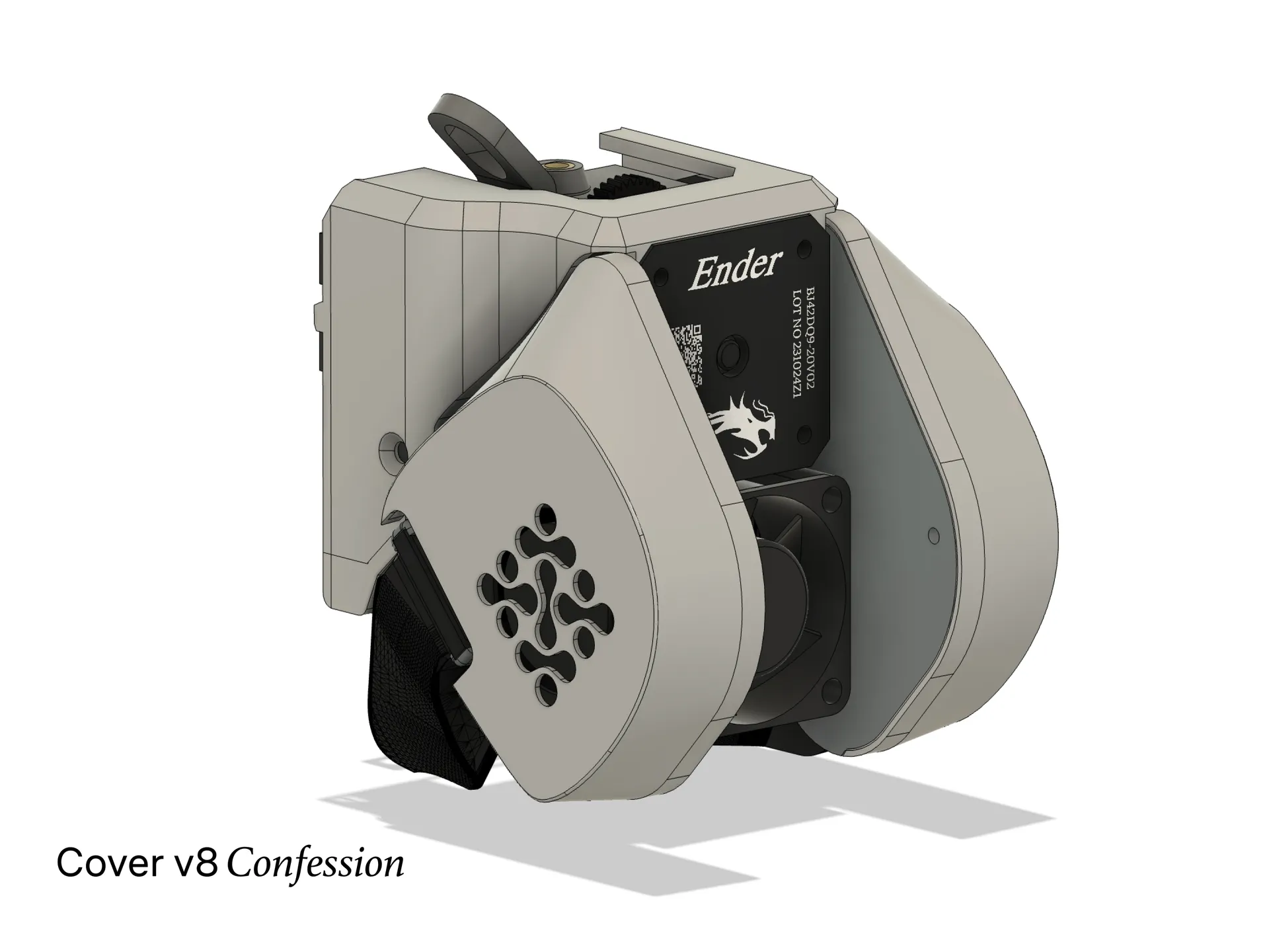
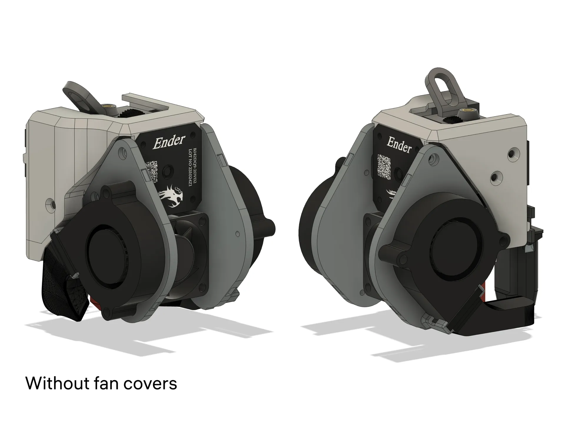
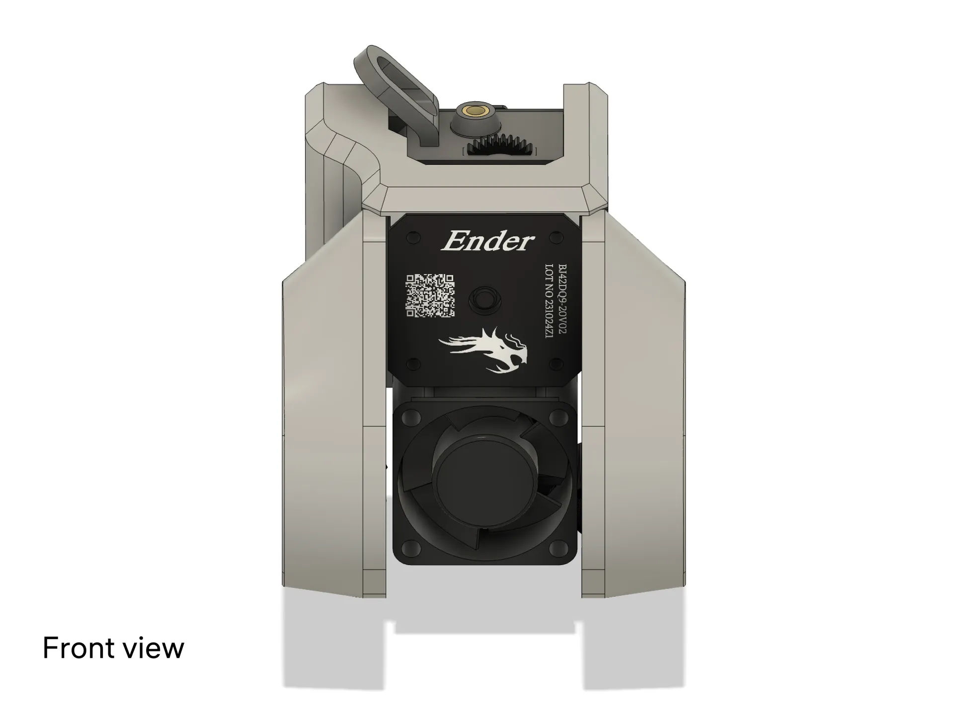
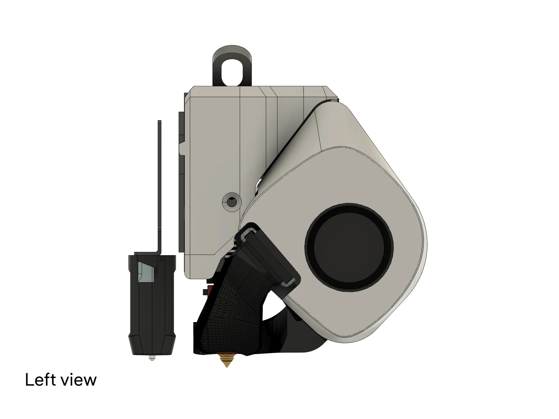
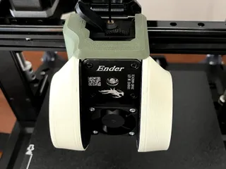
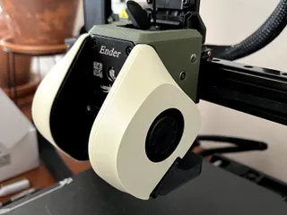
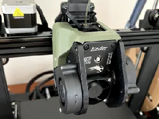
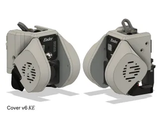
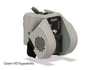
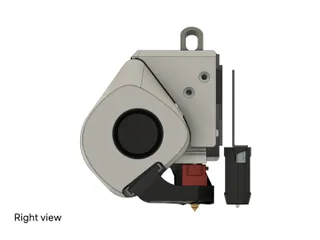
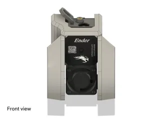
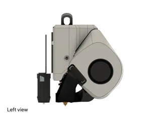
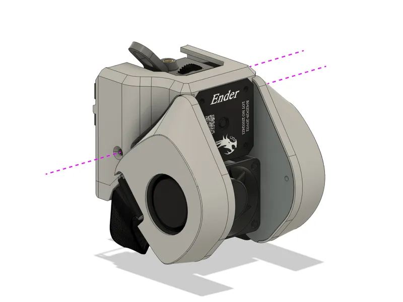
This is my version of the Ender 3 v3 KE cooling system, inspired by the LiteBurner - Ender 3 V3 KE Dual 5015 Fan Shroud. My version features a slimmer base, improved connections for the ducts and fans, hidden cable management, and aesthetic covers for a clean, streamlined look. The front is intentionally open to showcase the technical aesthetic of the extruder motor with the dragon logo and the large hotend fan below it.
I recommend this setup for anyone frustrated by the noisy stock cooling of the KE. Here’s a noise comparison before and after:
Print Settings
Use at least 3 perimeters and 15% infill.
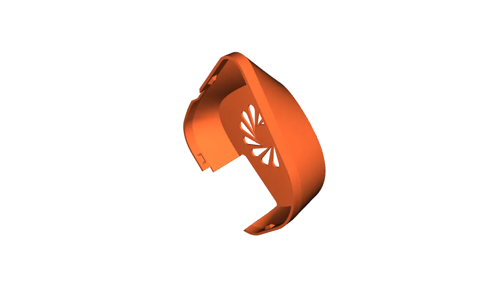
For Covers L & R, I used an Archimedean Chord pattern for the bottom surface, but feel free to choose your own design.
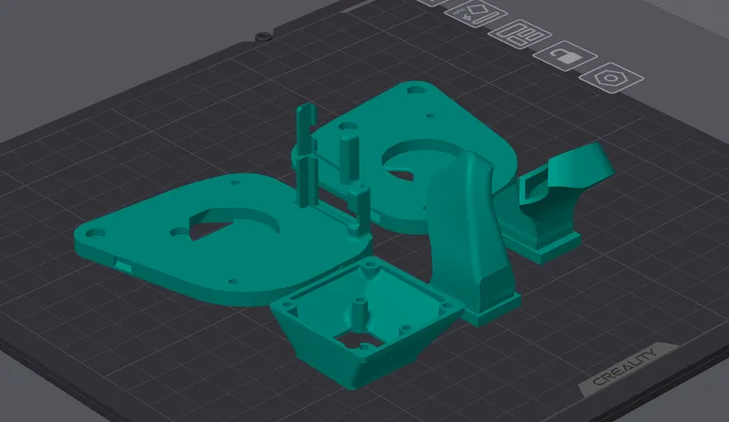
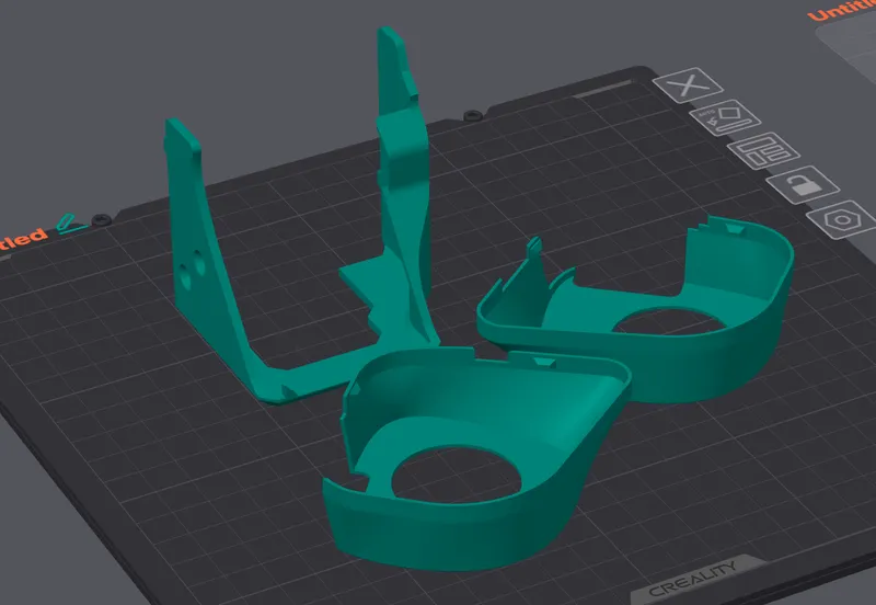
Orientation
Materials
- Base and Ducts: PETG or a more heat-resistant material.
- Covers: PLA is acceptable if your KE does not have an external cover. Otherwise use PETG too.
Supports
All parts, except for Base L, can be printed without supports. Base L has cable routing slots that require supports.
Bill of Materials
- 4020 Fan, 24V, 2 pins. Highly recommended, significant noise reduction. In my subjective observation, about 40% of the overall noise comes from the stock hotend fan. I used the Sunon Maglev, which is remarkably quiet compared to the stock KE fan. Link to product
- 5015 Fans, 24V, 2 pins (2 pieces). I used Sunon fans. At 100% speed, they are quieter than the stock fans, and at 70%, they are much quieter. Link to product
- M3 20mm Bolts (8 pieces): 4 for the 5015 fans and 4 for the 4020 fan. Flat heads preferred for better Covers installation. Link to product
- Stock Small Bolts *I think it's M2 11mm, but I'm not sure* (4 pieces). Used for attaching the 4020 fan adapter to the hotend heatsink. These bolts originally attach the stock hotend fan, so you don't need to buy them.
- Stock M3 5mm Bolts (3 pieces). Used for attaching the Top Cover. These bolts are originally used to attach the stock extruder casing, so you don't need to buy them.
- M3 5mm Bolts (4 pieces). For securing the Bases.
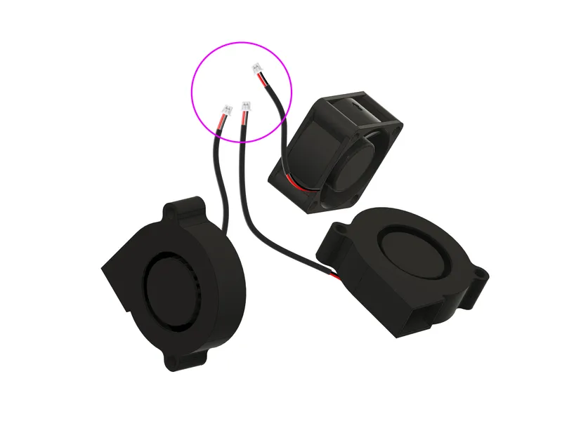
- JST 1.25mm Connectors (3 pieces): Can be salvaged from stock fans or bought new. Link to product
Important note: color coding might be incorrect on some connectors (mine did). If the fans do not work, the polarity of the wires might be reversed.
Assembly Instructions
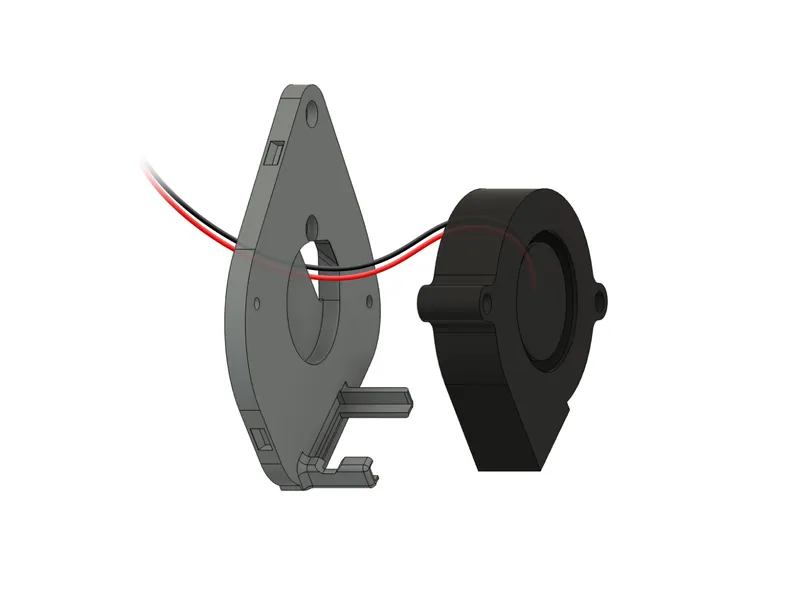
1. Prepare the Fans:
- Attach JST 1.25mm connectors to the fans. Soldering is recommended, but I twisted and heat-shrinked the connections. After installing the connectors, I recommend testing the fans by connecting them to the printer to ensure they work.
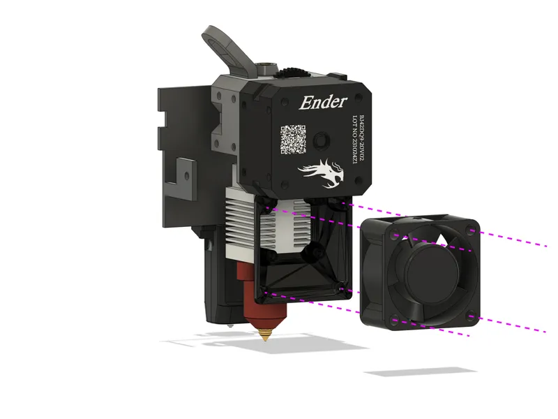
2. Install the Hotend Fan:
- Attach the 4020 fan adapter to the hotend heatsink using the stock bolts. (Download the original adapter model from its author, please.)
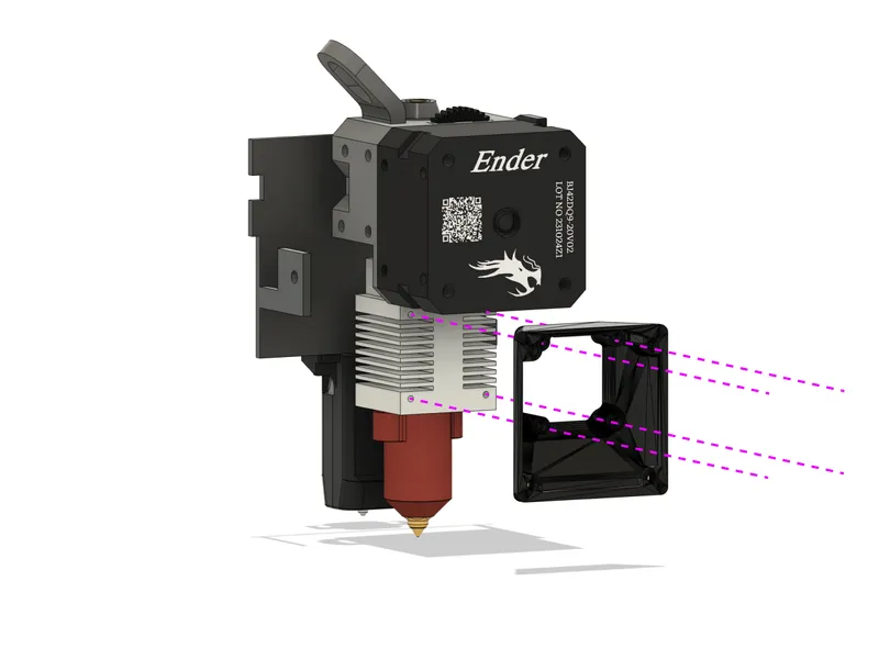
- Mount the 4020 fan to the adapter with M3 20mm bolts.
3. Install the Right Fan:
- Remove the tape holding the wires on the back of the 5015 fan.
- Thread the fan wires through the hole in Base R.
- Connect the fan by threading its wire between the hotend heatsink and the extruder frame.
- Secure Base R to the extruder motor with two M3 5mm bolts.

- Insert Duct R into the slots in Base R, partially.
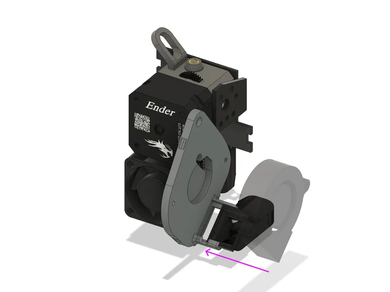
- Mount the fan in Duct R, then fully insert Duct R into Base R, ensuring the protrusion fits the slot.
- Secure the fan to Base R with two M3 20mm bolts
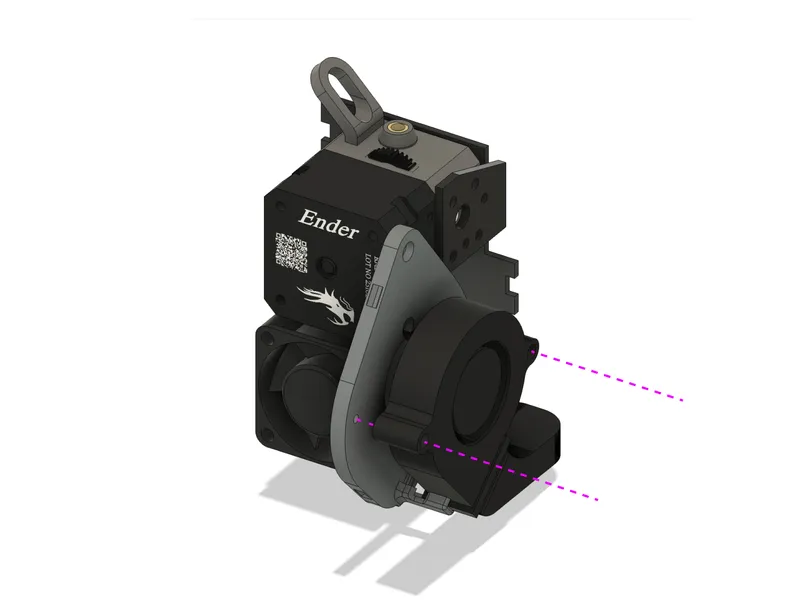
4. Install the Left Fan:
- Assemble Base L, Duct L, and the fan similarly to the right side. The fan does not obstruct access to the frame bolts, so the entire module can be installed assembled.

- Secure the left module to the frame with two M3 5mm bolts.
Be cautious with the left fan, hotend fan, and extruder motor wires. Route the wires of both fans through the lower routing slot and the motor wires through the upper routing slot in Base L. Ensure the wires are not pinched and that Base L fits snugly against the extruder motor. It may be a little tricky, but I believe you can do it.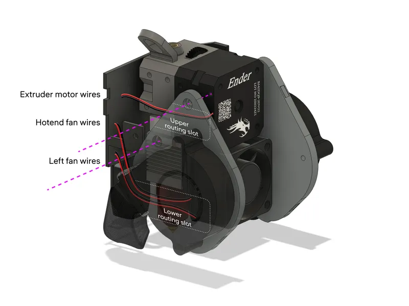
5. Final Steps:
- Power on the printer and verify all fans and the extruder motor are functioning.
- Attach Cover Top without securing it yet
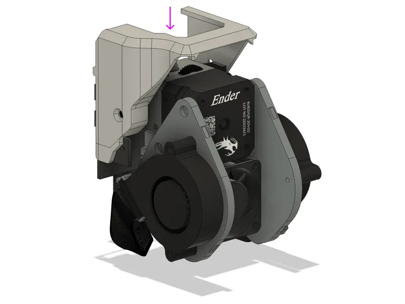
- Install Covers L and R by fitting their tabs into the slots in the base.
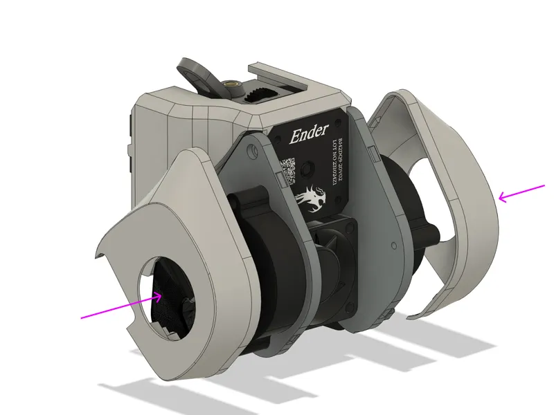
- Secure Cover Top with three M3 bolts.
Notes on Tolerances
My printer’s hotend mounting frame was quite misaligned from the factory. I made numerous prototypes to ensure a snug fit for all parts:
You might encounter assembly issues, particularly with the Top Cover and fan Covers. In the files, I've included a version of the Cover Top with increased tolerance (+1mm). Try this one if the standard version doesn't fit your setup. Otherwise, adjust the dimensions to suit your printer using the provided solid model files.
Note on LED Lighting from Original LiteBurner
I do not use LED lighting, so the main files do not include mounts for it. However, the “LED” folder contains a version of Base R with LED mounts, copied from the original LiteBurner file. There are also versions of Cover R with LED cutouts. I have not tested these versions, so feedback is appreciated.
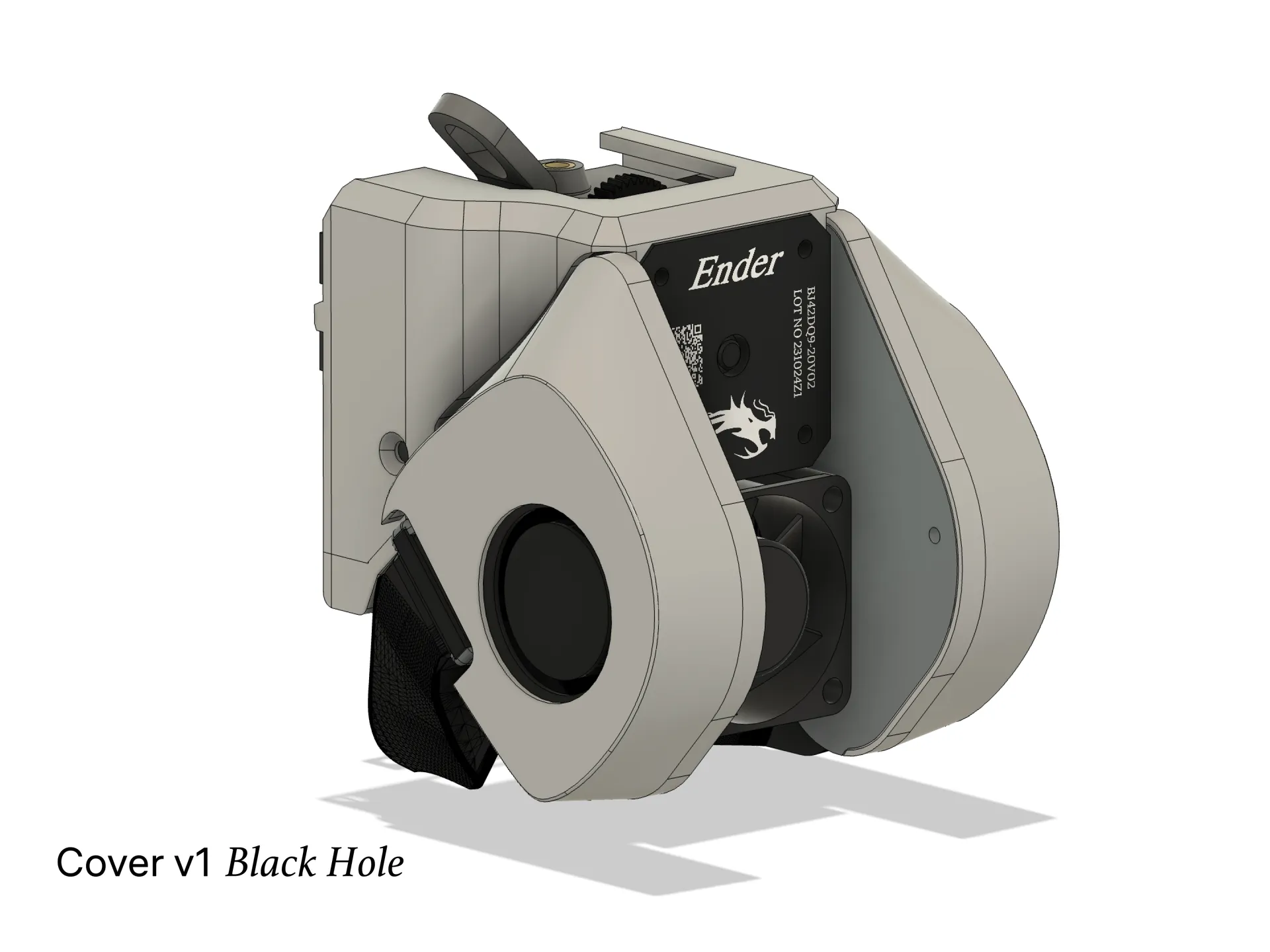
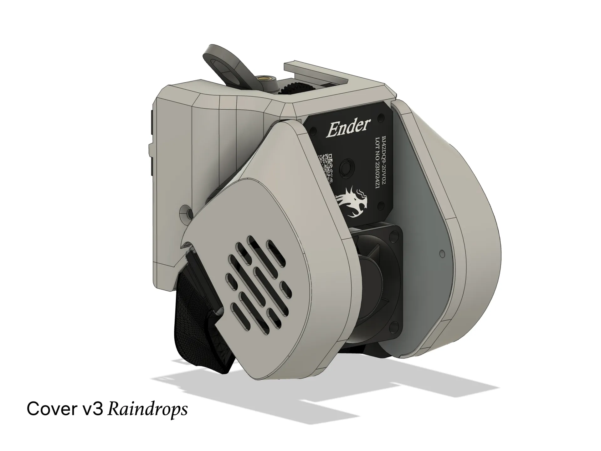
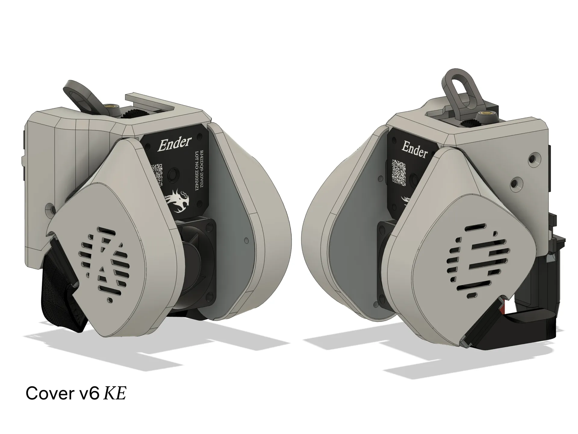
Note on Cover Versions
I have not printed all versions of the Covers, so there might be issues with some Grills. Please provide feedback if you face any problems.
Viva Open Source
i've included in the files is the original Fusion 360 file and the STEP file. Feel free to modify it, create different grills versions, and customize it to your needs.
Thanks and Credits
- Special thanks to Lite for the original cooling model. I used the bottom parts of the Ducts as is and adopted the brilliant fan placement design.
- Thanks to KILLbabylon for the 25-40mm fan bracket. The 4020 fan significantly reduced the noise level.
- Special thanks to ToxicXzombieG for the SE Extruder CAD model and Henlor for the K1 Hotend CAD Model. These CAD files were instrumental in assembling the KE extruder model and designing the cooling system around it.
If you liked the FatBurner model and would like to show your appreciation, you can support me with a donation. Thank you!
donationalerts.com/r/maxfat

Happy quiet printing to everyone! (づ ◕‿◕ )づ
Tags
Model origin
The author remixed this model.

Differences of the remix compared to the original
This version features
- a slimmer base
- improved connections for the ducts and fans
- hidden cable management
- and aesthetic covers for a clean, streamlined look
- fixed the issue with the wall thickness of the ducts.
Attention: This version does not support the installation of a glowing LED ring; only model lighting installation is available.