3D- Scanner V7 Open Source Project


Description
PDF3D- Scanner V7 Open Source Project
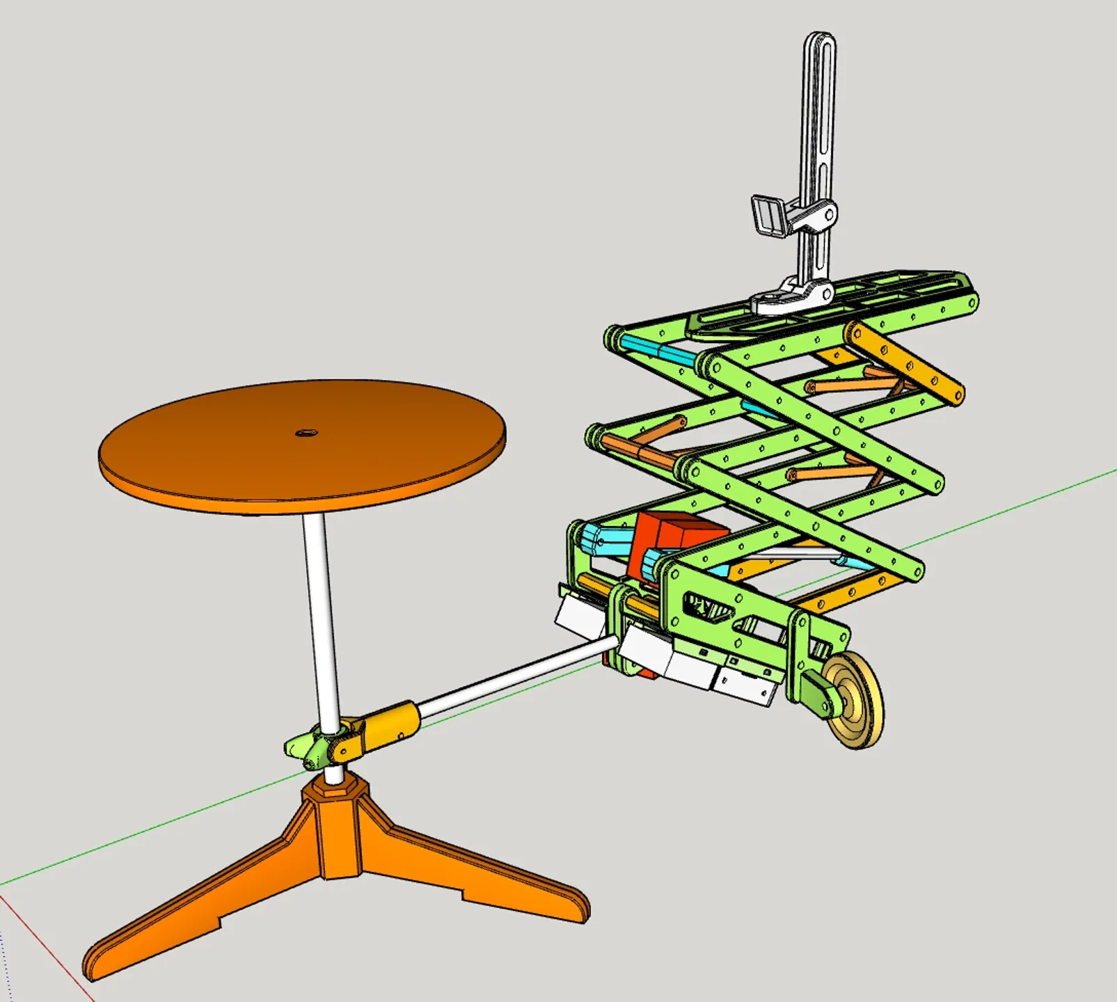
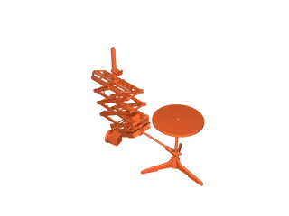
Ein 3D- Scanner bei dem die Kamera um das Objekt herumfährt,
anstatt das Objekt auf einem Tisch zu drehen,
bietet einige Vorteile bei der Photogrammetrie,
so dass ein realistischeres 3D- Bild entsteht.
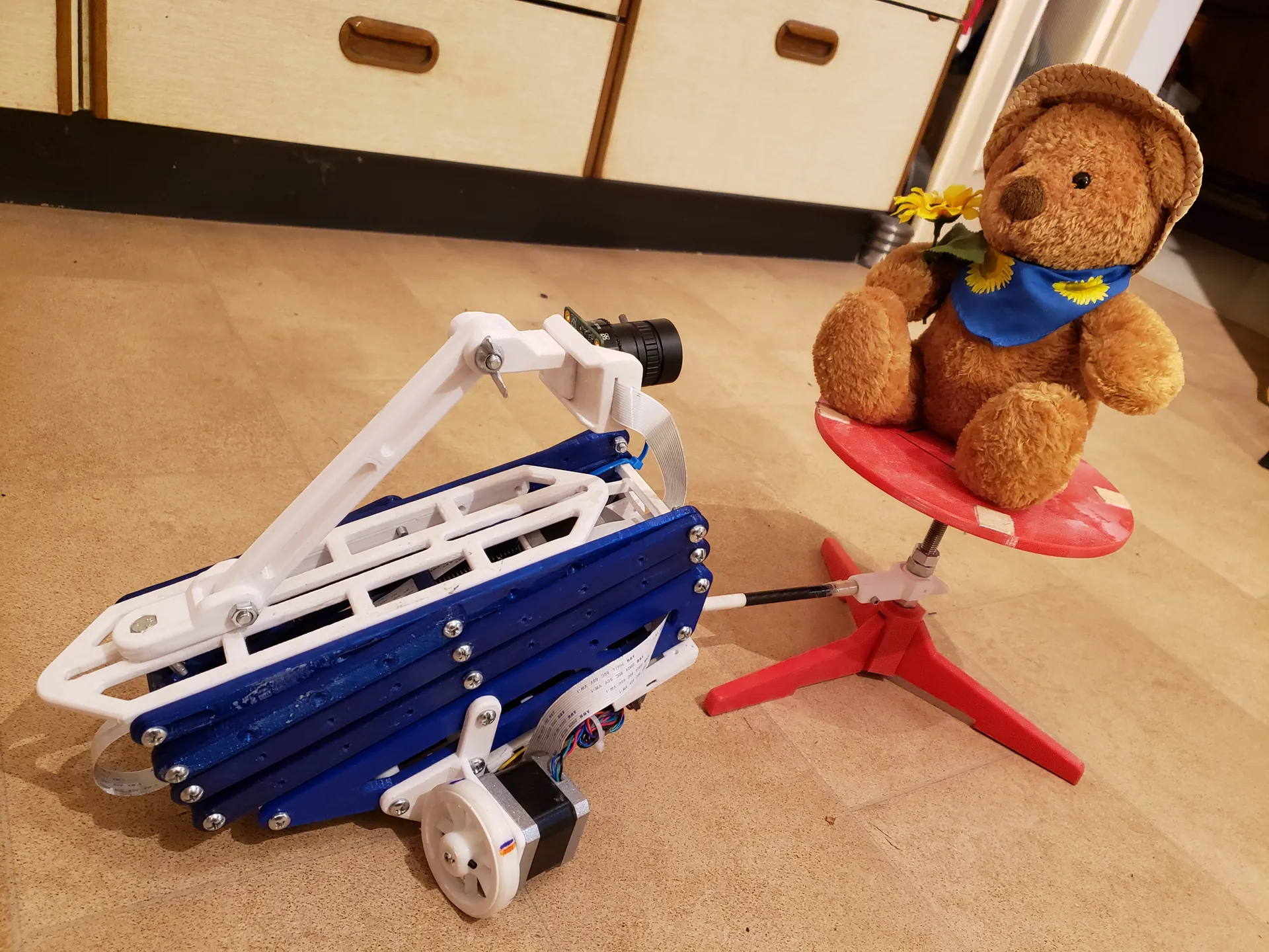
Der Scanner ist faltbar und schnell aufgebaut
Alle Teile sind leicht zu drucken.
(Druckerfläche mindestens 20 X 20 cm)
Die langen Teile diagonal auf dem Drucktisch einrichten
Mit PETG oder ABS- Filament (mindestens 3 Shells und 10% Infill)
Die 4,5 mm Bohrungen mit 4,5mm Bohrer glätten
und 5M Gewinde einschneiden
Die 2,5 mm Bohrungen mit 2,5mm Bohrer glätten
und 3M Gewinde einschneiden
Zusätzliches Material wird benötigt:
2 X Nema 17 Schrittmotoren mit Kabel
2 X Erweiterungsplatine für Schrittmotorantrieb:
Schutzmodul, A4988 DRV8825
(Alle drei Platineschalter auf 1 stellen für 1/32 Schritt Modus)
https://www.amazon.de/gp/product/B07NSVN9BR/ref=ox_sc_saved_image_1?smid=A3QSVUBYAY7YVC&psc=1
2 X Stepper Treiber A4988
Powerbank mit 12 Volt und 5 Volt USB Ausgang z. B.:
https://www.amazon.de/gp/product/B072HR211P/ref=ppx_yo_dt_b_asin_title_o09_s00?ie=UTF8&psc=1
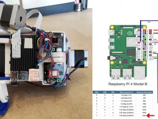
Raspberry Pi, Treiber, Motoren und Powerbank mit
Steckerkabeln entsprechend Schaltplan verkabeln
Alu- oder Carbon Rohr ⌀ 8mm, 220mm Länge
8M Gewindestange ca. 250mm,
10M Gewindestange ca. 250mm,
einige 3M, 5M Schrauben mit Muttern,
einige Kabelbinder,
Das Antriebsrad sitzt direkt auf der Achse des Schrittmotors.
Bei der Höhenverstellung wird eine Kupplung benötigt:
5mm Motorachse zu 8mm Gewindestange,
Für die Steuerung:
Raspbian- Image auf Raspberry Pi Speicherkarte kopieren
Raspberry Pi über z. B. VNC Viewer mit PC steuern.
Raspberry Pi Kamera installieren
Python installieren
Python Dateien auf Raspberry Pi kopieren
Motor library installieren:
from RpiMotorLib import RpiMotorLib
Zum Starten des Scans die entsprechende Python Datei starten.
nach dem Scan die Bilder z. B. mit WinSCP auf den PC übertragen
Für das Auslösen der Kamera:
Raspberry Kamera mit 1m Kabel verwenden (Dazu passende Python Datei starten)
oder nochmal 2 zusätzliche Relais an einen "angezapften" Kabelauslöser anschließen,
oder ein Mini- Servo (GPIO 14) mittels Adapter am Kameraauslöser anbringen und damit mechanisch den Auslöser betätigen, (entsprechende Python Datei starten).
oder mit evtl. Vorhandener WLAN- Verbindung der Kamera verbinden
(Für schwere Kameras die Rahmen Teile aus Aluprofil oder Hartholz fertigen)
Alternative Steuertechnik via Web Interface:
Für Raspberry Pi Schrittmotorsteuerung mit Aufsteckplatine
incl. Motortreiber
Für Arduino Schrittmotorsteuerung mit Aufsteckplatine
gibt es hier:
https://www.openscan.eu/shop?fbclid=IwAR15n-gMns8kVUlAEFDUwFpUH0eiaEAan2-cYIJAYgy4F5Z5BuBBclaqvx8
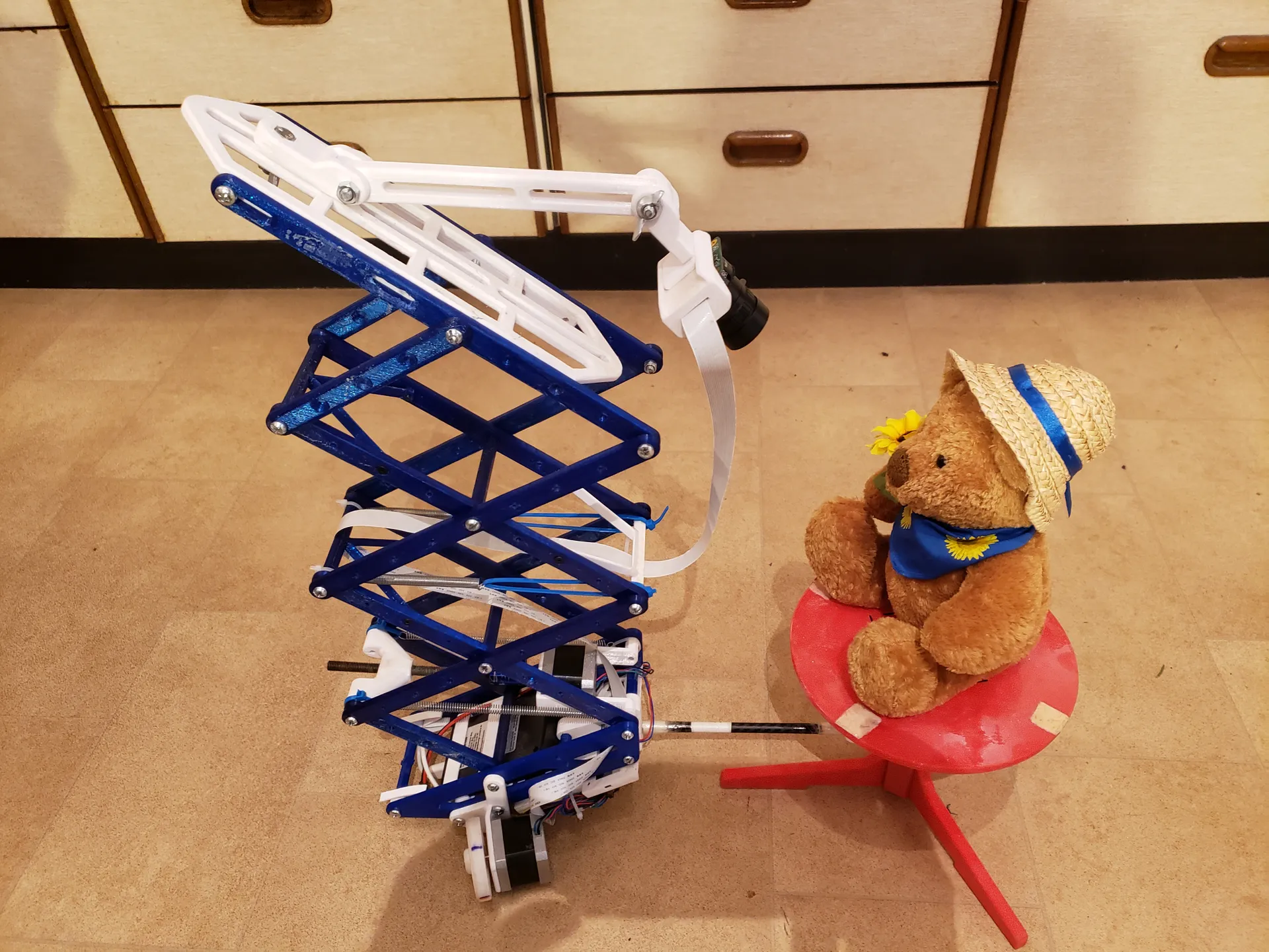
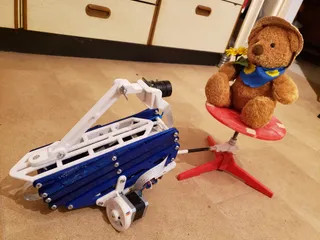
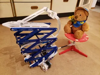
Anmerkung: Das Rad: “211121_P08C-Wheel-TPU-Print.stl” aus weichem TPU drucken und den Reifen: “211121_P08D-Wheel-Stabilisator.stl”zur Stabilisierung aufschieben. Das ermöglicht ein sanftes Beschleunigen des Steppermotors, so dass keine Beschleunigungsrampe in der Software nötig ist. Und um das Hochfahren des Scherenhubtisches zu erleichtern, 4 Zugfedern oder Gummibänder mit Kabelbindern befestigt, wie auf dem Bild, einbauen.
-----------------------------------------------------------------------------------
3D scanner V7 Open Source Project
A 3D scanner in which the camera moves around the object,
instead of rotating the object on a table,
offers some advantages in photogrammetry,
so that a more realistic 3D image is created.
The scanner is foldable and quick to set up
All parts are easy to print.
(Printer surface at least 20 X 20 cm)
Set up the long pieces diagonally on the print table
With PETG or ABS filament (at least 3 shells and 10% infill)
Smooth the 4.5 mm holes with a 4.5 mm drill
and cut 5M thread
Smooth the 2.5 mm holes with a 2.5 mm drill bit
and cut 3M thread
Additional material is required:
2 X Nema 17 stepper motors with cables
2 X expansion board for stepper motor drive:
Protection module, A4988 DRV8825
(Set all three circuit board switches to 1 for 1/32 step mode)
https://www.amazon.de/gp/product/B07NSVN9BR/ref=ox_sc_saved_image_1?smid=A3QSVUBYAY7YVC&psc=1
2 X stepper driver A4988
Power bank with 12 volt and 5 volt USB output z. B .:
https://www.amazon.de/gp/product/B072HR211P/ref=ppx_yo_dt_b_asin_title_o09_s00?ie=UTF8&psc=1
Raspberry Pi, drivers, motors and power bank with
Wire the connector cables according to the wiring diagram
Aluminum or carbon tube ⌀ 8mm, 220mm length
8M threaded rod approx. 250mm,
10M threaded rod approx. 250mm,
some 3M, 5M bolts with nuts,
some zip ties,
The drive wheel sits directly on the axis of the stepper motor.
A coupling is required for height adjustment:
5mm motor axis to 8mm threaded rod,
For the control:
Copy the Raspbian image to the Raspberry Pi memory card
Raspberry Pi via z. B. Control VNC Viewer with PC.
Copy Python files to Raspberry Pi
Install the motor library
from RpiMotorLib import RpiMotorLib
To start the scan, start the corresponding Python file.
after the scan the images z. B. transferred to the PC with WinSCP
To trigger the camera:
Use a Raspberry camera with a 1m cable (start the appropriate Python file)
or connect 2 additional relays to a "tapped" cable release,
or attach a mini servo (GPIO 14) to the camera trigger using an adapter and thus mechanically activate the trigger (start the corresponding Python file).
or connect to any existing WiFi connection on the camera
(For heavy cameras, make the frame parts from aluminum profiles or hardwood)
Alternative control technology via web interface:
For Raspberry Pi stepper motor control with plug-in board
including motor driver
For Arduino stepper motor control with plug-in board
Is there ... here:
https://www.openscan.eu/shop?fbclid=IwAR15n-gMns8kVUlAEFDUwFpUH0eiaEAan2-cYIJAYgy4F5Z5BuBBclaqvx8
Note: Print the wheel: “211121_P08C-Wheel-TPU-Print.st” out of soft TPU and slide on the tire: “211121_P08D-Wheel-Stabilisator.stl” for stabilization. This enables the stepper motor to accelerate gently so that no acceleration ramp is required in the software. And to make it easier to raise the scissor lift table, install 4 tension springs or rubber bands attached with cable ties, as shown in the picture.
Tags
Model origin
The author hasn't provided the model origin yet.


